

Martin CX-10 Extreme User Manual
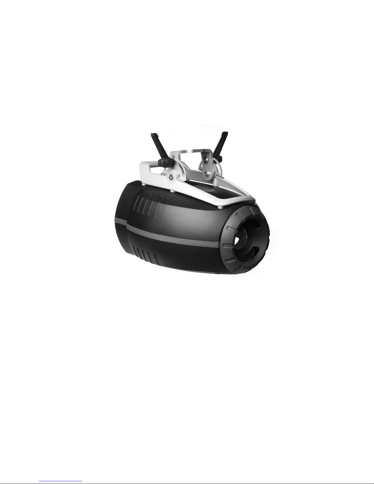
CX-10 Extreme
user manual
217109
340
412
© 2004 Martin Professional A/S, Denmark.
All rights reserved. No part of this manual may be
reproduced, in any form or by any means, without
permission in writing from Martin Professional A/S,
Denmark.
Printed in Denmark.
P/N 35000129,Rev. C

3
Introduction. . . . . . . . . . . . . . . . . . . . . . . . . . . . . . . . . . . . . . . . . . . . . . . . . . . . . . 4
Features .................................................................................................................................................4
About this manual ............................................................. .. ........................................ .. ... .......................4
Safety. . . . . . . . . . . . . . . . . . . . . . . . . . . . . . . . . . . . . . . . . . . . . . . . . . . . . . . . . . . 5
Safety precautions ...................................................... ... ....................................... ... ... ............................5
Setup . . . . . . . . . . . . . . . . . . . . . . . . . . . . . . . . . . . . . . . . . . . . . . . . . . . . . . . . . . . 6
Unpacking ..............................................................................................................................................6
AC power ................................................................................................................................................6
Installation ..............................................................................................................................................7
Connecting the serial data link ...............................................................................................................8
Control Panel . . . . . . . . . . . . . . . . . . . . . . . . . . . . . . . . . . . . . . . . . . . . . . . . . . . . 9
Menu navigation ....................................................................................................................................9
Address selection ................................. .. ........................................ .. ... ...................................................9
Tailoring performance ..........................................................................................................................10
Information readouts ............................................................................................................................10
Test and service utilities .......................................................................................................................11
DMX-512 control. . . . . . . . . . . . . . . . . . . . . . . . . . . . . . . . . . . . . . . . . . . . . . . . . 13
Lamp power ............................................................................................ ..............................................13
Effect position .......................................................................................................................................13
Speed control .......................................................................................................................................14
Optical configuration . . . . . . . . . . . . . . . . . . . . . . . . . . . . . . . . . . . . . . . . . . . . . 15
Effect wheel ..........................................................................................................................................15
Color filters ...........................................................................................................................................18
Optional lenses .....................................................................................................................................19
Animation wheels .................................................................................................................................22
Service. . . . . . . . . . . . . . . . . . . . . . . . . . . . . . . . . . . . . . . . . . . . . . . . . . . . . . . . . 28
Lamp ....................................................................................................................................................28
Cleaning ...............................................................................................................................................29
Lubrication ............................................................................................................................................30
Replacing fuses ....................................................................................................................................30
Updating software ........................................ ... ....................................... ... ... ........................................31
DMX protocol . . . . . . . . . . . . . . . . . . . . . . . . . . . . . . . . . . . . . . . . . . . . . . . . . . . 32
Control menu . . . . . . . . . . . . . . . . . . . . . . . . . . . . . . . . . . . . . . . . . . . . . . . . . . . 34
Error messages . . . . . . . . . . . . . . . . . . . . . . . . . . . . . . . . . . . . . . . . . . . . . . . . . 37
Troubleshooting. . . . . . . . . . . . . . . . . . . . . . . . . . . . . . . . . . . . . . . . . . . . . . . . . 38
PCB connections . . . . . . . . . . . . . . . . . . . . . . . . . . . . . . . . . . . . . . . . . . . . . . . . 39
Specifications - CX-10 . . . . . . . . . . . . . . . . . . . . . . . . . . . . . . . . . . . . . . . . . . . . 40

4 CX-10
I
NTRODUCTION
Features
Thank you for selecting the Martin CX-10 Extreme. Some of the many features include:
• efficient, 3000 hour, 250 watt discharge lamp
• 12 interchangeable dichroic colors plus open
• double-sided, 13-position, effect wheel which enables overlapping effects.
• motorized focus
• full-range dimming
• fast blackout and strobe effects
• coated optics
• switch-selectable power supply settings
• integrated mounting bracket
• easy-to-clean cooling fan
• optional wide and narrow angle lens kits available
• optional animation kit available
About this manual
Please check the Martin web site at http://www.martin.com for the latest product software and
documentation.
Comments or suggestions regarding this document may be e-mailed to service@martin.com or sent by
standard mail to:
Martin Professional A/S
Olof Palmes Allé 18
DK-8200 Aarhus N, Denmark
Attn: Service Department
Please review the important safety precautions in this manual before installing and operating the fixture.

Safety 5
S
AFETY
Warning! This product is for professional use only. It is not for household use.
This product presents risks of lethal or severe injury due to fire and heat, electric shock, ultraviolet radiation,
lamp explosion, and falls. Read this manual before powering or installing the fixture, follow the safety
precautions listed below and observe all warnings in this manual and printed on the fixture. If you have
questions about how to operate the fixture safely, please contact your Martin dealer or call the Martin
24-hour service hot line at +45 70 200 201.
Safety precautions
PROTECTION FROM ELECTRIC SHOCK
• Disconnect the fixture from AC power before removing or installing the lamp, fuses, or any part, and when
not in use.
• Always ground (earth) the fixture electrically.
• Use only a source of AC power that complies with local building and electrical codes and has both overload
and ground-fault protection.
• Do not expose the fixture to rain or moisture.
• Refer any service operation not described in this manual to a qualified technician.
PROTECTION FROM UV RADIATION AND LAMP EXPLOSION
• Never operate the fixture with missing or damaged lenses and/or covers.
• When replacing the lamp, allow the fixture to cool for at least 15 minutes before opening the fixture or
removing the lamp. Protect your hands and eyes with gloves and safety glasses.
• Do not stare directly into the light. Never look at an exposed lamp while it is lit.
• Replace the lamp if it becomes defective or worn out, or before usage exceeds the maximum service life.
PROTECTION FROM BURNS AND FIRE
• Never attempt to bypass the thermostatic switch or fuses. Always replace defective fuses with ones of the
specified type and rating.
• Keep all combustible materials (for example fabric, wood, paper) at least 0.1 meter (4 inches) awa y from the
fixture. Keep flammable materials well away from the fixture.
• Do not illuminate surfaces within 0.3 meters (12 inches) of the fixture.
• Provide a minimum clearance of 0.1 meters (4 inches) around fans and air vents.
• Never place filters or other materials over the lens.
• The exterior of the fixture can get very hot. Allow the fixture to cool for at least 5 minutes before handling.
• Do not modify the fixture or install other than genuine Martin parts.
• Do not operate the fixture if the ambient temperature (T
a
) exceeds 40° C (104° F).
PROTECTION FROM INJURY DUE TO FALLS
• When suspending the fixture, verify that the structure can hold at least 10 times the weight of all installed
devices.
• Verify that all external covers and rigging hardware are securely fastened and use an approved means of
secondary attachment such as a safety cable.
• Block access below the work area whenever installing or removing the fixture.
6 CX-10
S
ETUP
Unpacking
The CX-10 comes with:
• MSD 250/2 lamp
• 3-meter, 3-wire IEC power cable
•user manual
The packing material is carefully designed to protect the fixture during shipment - always use it or a custom
flight case to transport the fixture.
AC power
Warning! For protection from electric shock, the fixture must be grounded (earthed). The power
supply shall have overload and ground-fault protection.
Important! Verify that power supply settings match the local AC supply before use.
The CX-10 is factory configured for 230 V / 50 Hz operation. If your AC power supply is
different, the fixture must be configured for the local voltage and frequency. Always use
the voltage settings that are equal to or next highest to your AC supply.
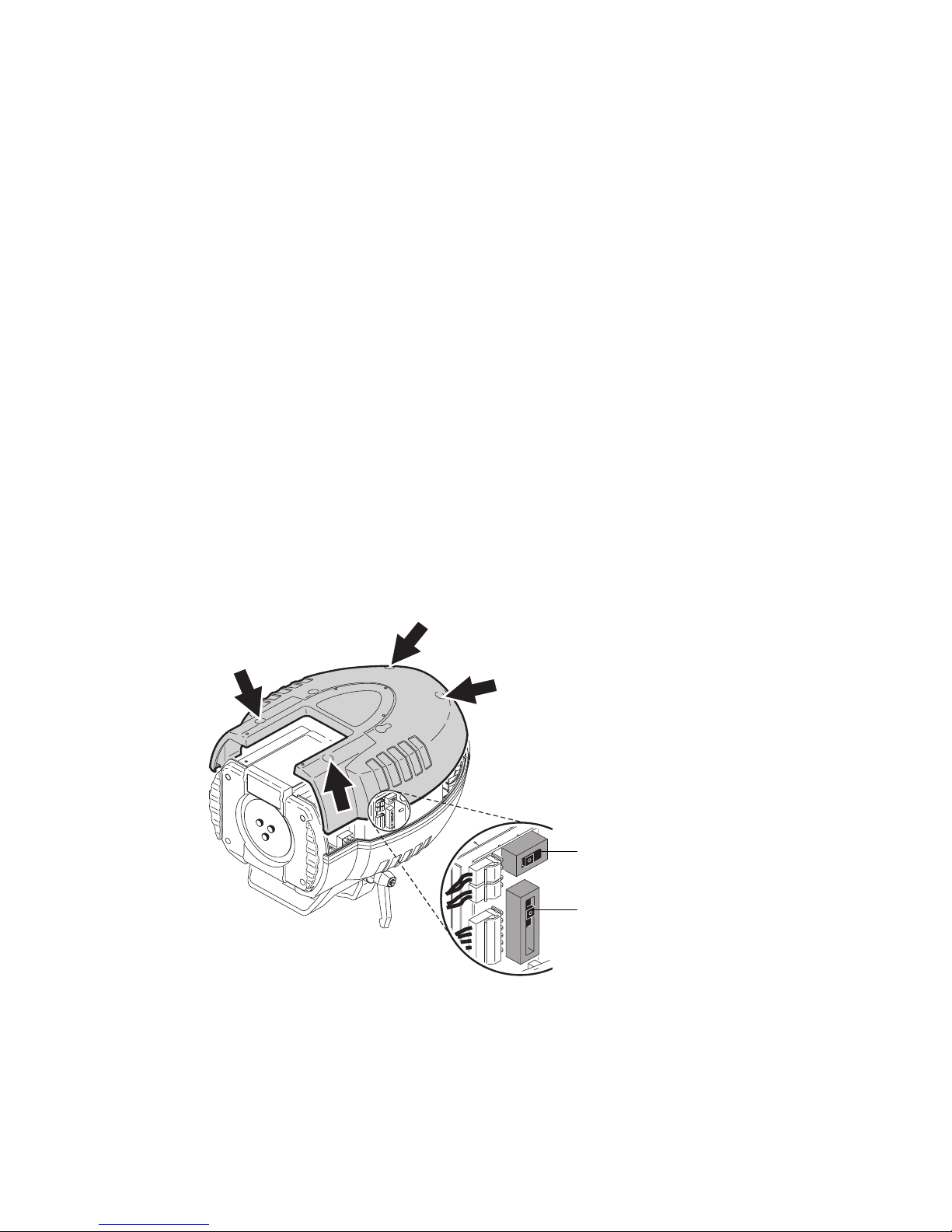
CONFIGURING FOR LOCAL AC POWER
1 Disconnect the fixture from power.
2 Remove the 4 cover screws and lift off the front cover.
3 Locate the selection switches and the settings label, which is by the color wheel. Move the voltage switch to
the setting that is equal to or higher than the local AC voltage. If your voltage falls between 2 settings,
always select the higher voltage. For example, if the AC voltage is 215 V, use the 230 V setting instead of
210 V.
4 Move the frequency switch to the setting that matches the local AC frequency: 50 or 60 Hz.
5 Replace the cover.
Frequency
Voltage

Setup 7
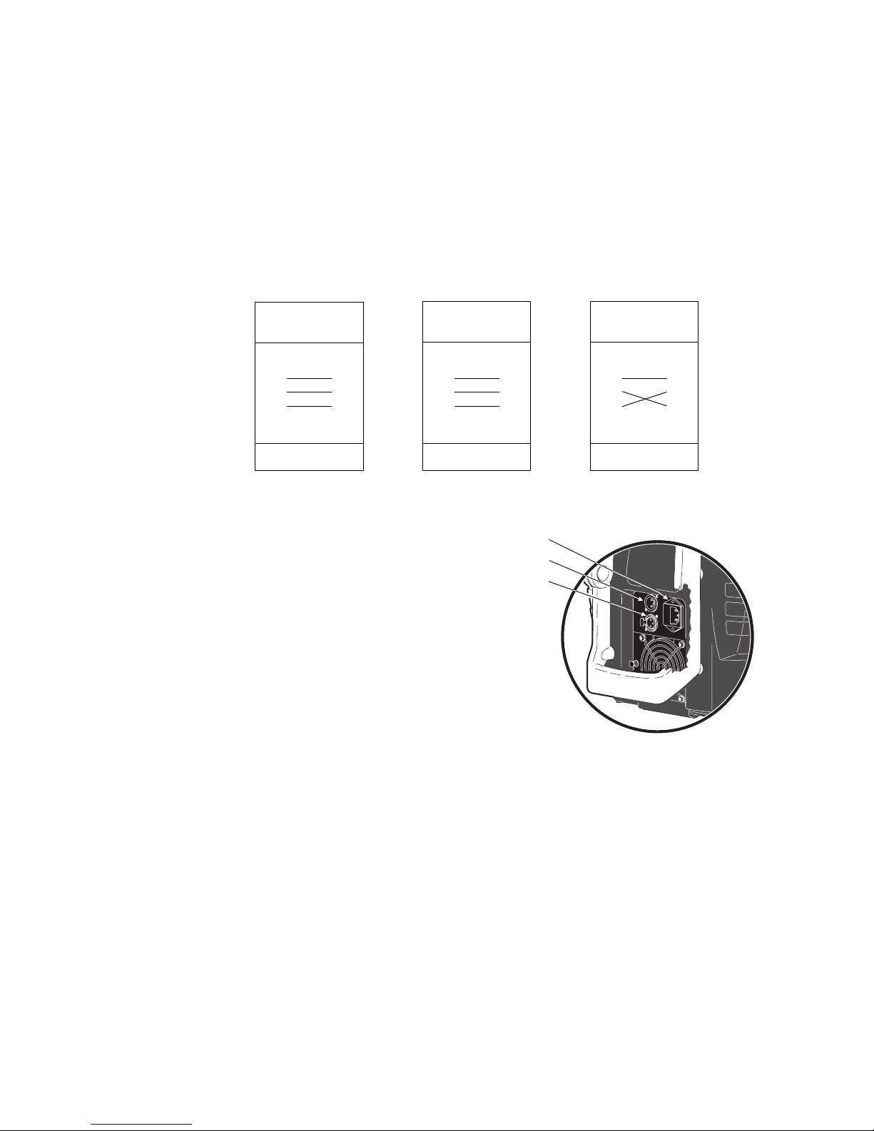
INSTALLING A PLUG ON THE POWER CABLE
The power cable must be fitted with a grounding-type cord cap that fits your power distribution system.
Consult an electrician if you have any doubts about proper installation.
• Following the cord cap manufacturer’ s instructions, connect the yellow and green wire to ground (earth), the
brown wire to live, and the blue wire to neutral. The table below shows some pin identification schemes.
APPLYING POWER
Warning! The power cables must be undamaged and
rated for the electrical requirements of all
connected devices.
Important! Powering through a dimmer system can
damage the fixture.
1 Verify that the supply cable is undamaged and rated
for the current requirements of all connected devices.
2 Plug the prepared power cable into the AC socket and
a grounded AC power supply.
Installation
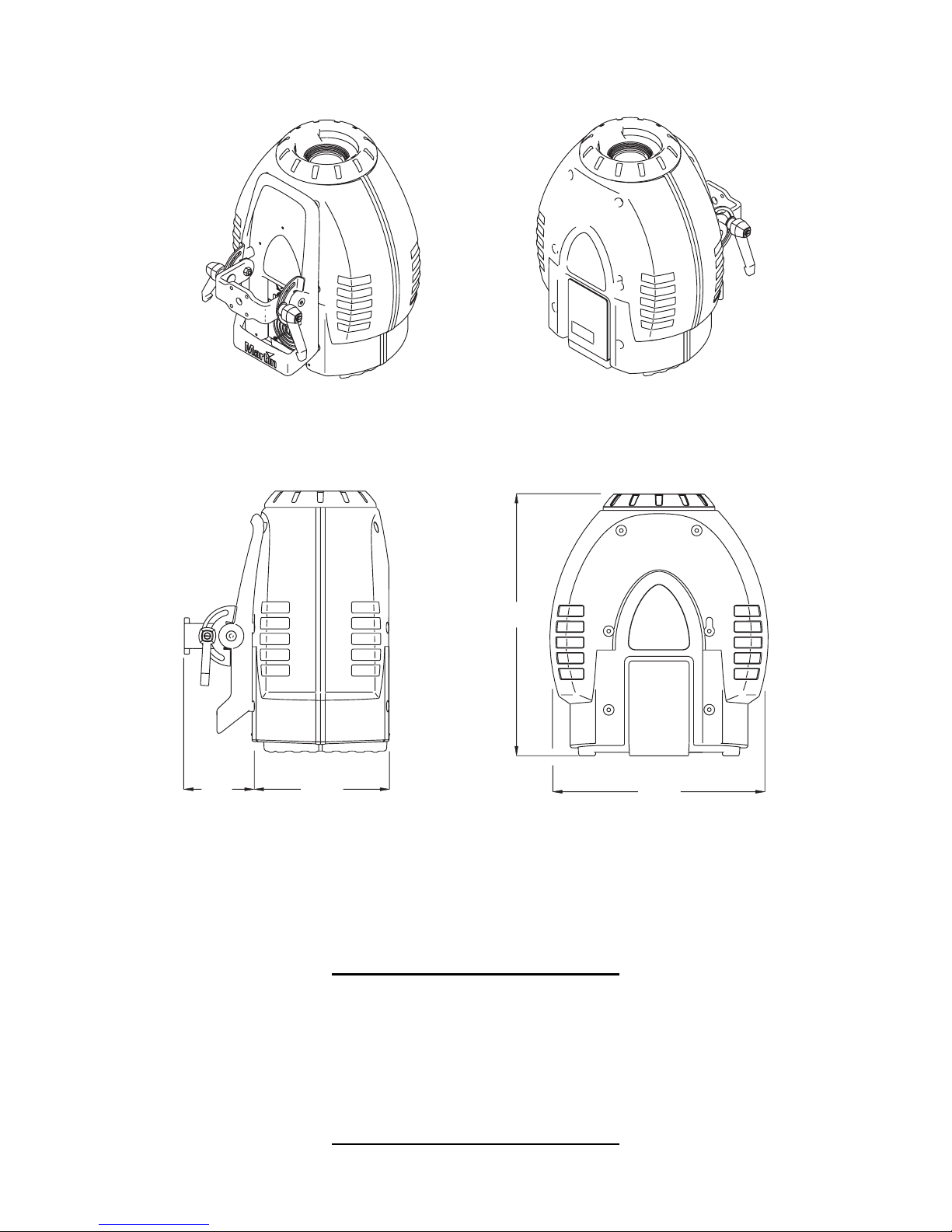
LOCATION AND ORIENTATION
The CX-10 may be installed in any orientation. It can be fastened directly to a suitable surface, hung with a
rigging clamp, or placed directly on a level surface.
For safe operation, install the CX-10 in a location where
• the fixture is at least 0.1 meters (4 inches) away from combustible materials
• the fixture is protected from rain and moisture
• there is at least 0.1 meters (4 inches) clearance around the fan and control panel
• there are no flammable materials nearby
RIGGING OR MOUNTING THE CX-10
Warning! Block access below the work area before proceeding.
Warning! Always use a secure means of secondary attachment.
1 If using a rigging clamp (not included), verify that it is undamaged and can bear at least 10 times the fixture’s
weight. Bolt the clamp securely to the bracket with a grade 8.8 (minimum) M12 bolt and lock nut, or as
recommended by the clamp manufacturer, through the 13 mm hole in the center of the mounting bracket.
2 If fastening the fixture directly, verify that the hardware (not included) and mounting surface can bear at least
10 times the fixture’s weight. The four 6.2 mm holes and/or the 13 mm hole in the mounting bracket may be
used to fasten the fixtures.
3 Verify that the structure can suppor t at least 10 times the weight of all installed fixtures, clamps, cables,
auxiliary equipment, etc.
4 Working from a stable platform, clamp or fasten the fixture to the structure.
Wire Pin Marking Screw color
brown live “L” yellow or brass
blue neutral “N” silver
yellow/green ground green
Table 1: Plug wiring
AC input & fuse holder
Data input
Data output
8 CX-10
5 Install a safety cable that can hold at least 10 times the weight of the fixture through/over the suppor t and
anywhere through the fixture’s aluminum frame.
6 Loosen the swivel locks and tilt the fixture to the desired angle. Turn the swivel locks clockwise to tighten.
When a handle reaches its limit, pull it out, turn counterclockwise, release, and continue tightening.
7 Verify that the fixture meets the location requirements listed previously.
Connecting the serial data link
The CX-10 has locking 3-pin data input and outpu t sockets that are wired for use with DMX devices
with pin 1 to shield, pin 2 to cold (-) and pin 3 to hot (+). As some devices have 5-pin connectors, or 3-pin
connectors with reversed polarity on pins 2 and 3, the following adaptor cables may be required.
1 Connect the controller’s output to the fixture’s data
input. For a DMX controller with 5-pin output, use a
cable with a 5-pin male and a 3-pin female XLR
connector.
2 Connect the output of the fixture closest to the
controller to the input of the next fixture. If connecting a
fixture with pin 3 hot to a fixture with pin 3 cold, use a
phase-reversing adaptor.
3 To terminate the link, insert a male 120 Ω XLR
termination plug in the output of the last fixture.
TIPS FOR BUILDING A SERIAL LINK
• Use shielded twisted-pair cable designed for RS-485
devices: standard microphone cable cannot transmit DMX data reliably over long runs. For links up to 300
meters (1000 ft.) long, you can use 24 AWG, low capacitance, 85-150 ohm characteristic impedance,
shielded cable with 1 or more twisted pairs. For runs up to 500 meters (1640 ft.) use 22 AWG cable. Use an
amplifier if the serial link exceeds 500 meters.
• Never use a “Y” connector to split the link. To split the serial link into branches use a splitter such as the
Martin 4-Channel Opto-Isolated RS-485 Splitter/Amplifier.
• Do not overload the link. Up to 32 devices may be connected on a serial link.
• Terminate the link by installing a termination plug in the output socket of the last fixture on the link. The
termination plug, which is simply a male XLR connector with a 120 ohm, 0.25 watt resistor soldered
between pins 2 and 3, “soaks up” the control signal so it does not reflect back down the link and cause
interference. If a splitter is used, terminate each branch of the link.
Phase-Reversing
Adaptor
Male Female
1
2
3
1
2
3
3-pin to 3-pin
P/N 11820006
Adaptor
Male Female
1
2
3
4
5
1
2
3
5-pin to 3-pin
P/N 11820005
Adaptor
Male Female
1
2
3
1
2
3
4
5
3-pin to 5-pin
P/N 11820004
Figure 1: Cable adaptors
AC input & fuse holder
Data input
Data output
Control Panel 9
C
ONTROL
P
ANEL
You set the address and personalities, read out data, and execute service utilities from the control panel.
Settings can also be changed remotely via the serial link with the Martin MP-2 uploader.
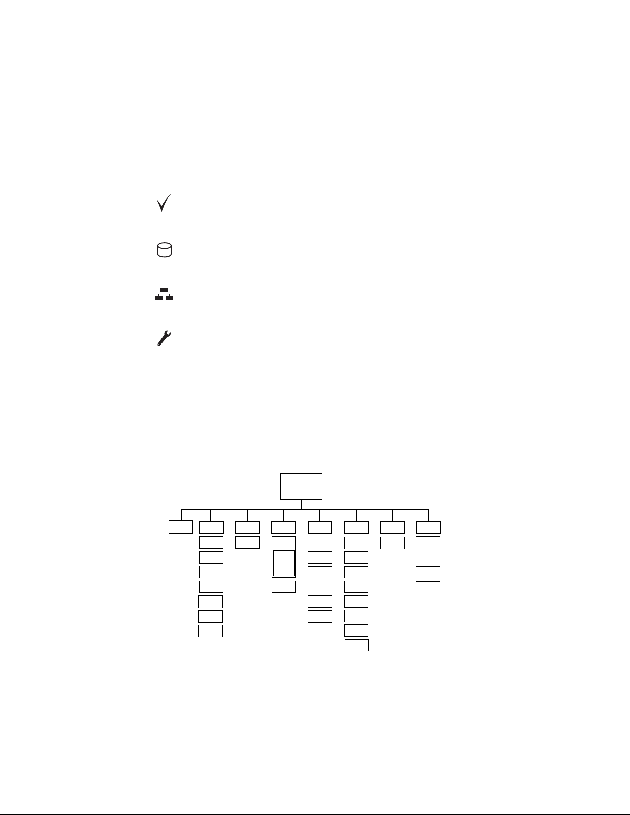
There are four small symbols that can appear in the control panel display:
Menu navigation
See also the control menu table starting on page 34.
The DMX address and any error messages are displayed after the fixture resets. To enter the menu, press
[menu]. Use the [up] and [down] keys to move within the menu. To select a function or submenu, press
[enter]. To escape a function or menu, press [menu].
Address selection
The CX-10 requires 10 channels for DMX control. The address, also known as the start channel, is th e first
channel used to receive instructions from the controller. For independent control, each fixture must be
assigned its own address and non-overlapping control channels. Two CX-10s can share the same address
Power is on and the fixture is ready.
The fixture is writing to memory. Do not power off the fixture while this symbol is
lit.
The fixture is receiving DMX.
Error. See “Error messages” on page 37 and “Troubleshooting” on page38.
AddR
dMXL UTIL
Address/
Messages
STCO
SHUT
....
EFSP
AdJ
PCbT
UPLd
TSEQPERS dFSE INFO
SCUT
dISP
dINT
dLOF
ALON
FAC T
CAL
dFOF
TIME
HRS
L HR
L ST
VERdRES
RST
L ON
LoFF
EFCT
SHUT
dIM
COL
FOC
RATE
qUAL
MAN
RUN
WHEL

10 CX-10
if they are to respond identically: they will receive the same instructions and individual control will not be
possible.
TO SET THE DMX ADDRESS
1 Apply power to the CX-10. Press [menu] to enter the main menu.
2 Select AddR using the [up] and [down] keys. Press [enter].
3 Select an address (start channel) from 1 to 502 using the [up] and [down] keys. Press [enter]. Press [menu]
to return to the main menu.
Tailoring performance
MOVEMENT
SCUT
, the shortcuts setting, deter mines whether the color and gobo wheels scroll past open when
changing positions. When set to
ON, the wheels can “take a shortcut” and scroll through open wh en th is is
the shortest path to the next position. The wheels do not scroll past open when
SCUT is set to OFF.
DISPLAY
The display menu (PERS>dISP) determines whether the display remains lit or not. Select ON to have
the display remain lit, or OFF to extinguish the display two minutes after the last key press.
To flip the display for easier reading, press [up] and [down] simultaneously.
The display intensity setting (
PERS>dINT) controls display brightness. You can select AUTO fo r
automatic dimming of the display using the built-in light sensor, or manually select an intensity level from 10
to 100.
LAMP POWER
There are two settings that modify lamp control: Automatic Lamp On (PERS>ALON) and DMX Lamp-Off
(
PERS>DLoF).
There are three options for automatic lamp control: ON, OFF, and DMX. When ALON is OFF, the lamp
remains off until a lamp-on command is received from the controller. When
ALON is ON, the lamp strikes
automatically after the fixture is powered on. When
ALON is set to DMX, the lamp strikes automatically
when the fixture receives DMX data, and it extinguishes automatically 15 minutes after DMX data is lost.
When ALON is either ON or DMX, lamp strike timing is determined by the fixture address to prevent all
lamps from striking at once.
The DMX Lamp-Off setting effects how the lamp can be turned off. When
dLOF is ON, lamp power can be
switched off by sending a DMX value from 248 to 255 on channel 1 for five seconds. When
dLOF is OFF,
the lamp-off command will not work unless special conditions are met. Refer to the DMX protocol.
RESET
The fixture can be reset from the controller if DMX reset (PERS>dRES) is ON. If DMX reset is OFF, this
command will not work unless special conditions are met. Refer to the DMX protocol.
DEFAULT SETTINGS
The fixture can be reset to its factory default settings by selecting dFSE>FACT>LOAd.
Information readouts
POWER-ON HOURS
Read the total number of hours the fixture has been on since fabrication (INFO>TIME>HRS>TOTL),
and the number of hours on since the counter was last reset (
INFO>TIME>HRS>RSET). This can be
used to track maintenance intervals. Press [up] for 5 seconds while displayed to reset.

Control Panel 11
LAMP HOURS
Read the total number of lamp hours since fabrication (INFO>TIME>L HR>TOTL), and the number
of lamp hours since the counter was last reset (
INFO>TIME>L HR>RSET). Reset this counter after
installing a new lamp. Press [up] for 5 seconds while displayed to reset.
LAMP STRIKES
Read the total number of lamp strikes (INFO>TIME>L ST>TOTL), and the number of lamps strikes
since the counter was last reset (
INFO>TIME>L ST>RSET). Reset this counter when installing a
new lamp. Press [up] for 5 seconds while displayed to reset.
FIRMWARE VERSION
INFO>VER
displays the firmware version number. The firmware version is also displayed briefly at
startup.
Test and service utilities
DMX READOUT
The DMX log (dMXL) menu provides useful information for troubleshooting control problems.
RATE displays the DMX refresh rate in packets per second. Values lower than 10 or higher than 44 may
result in erratic performance, especially when using tracking control.
QUAL displays the quality of the received DMX data as a percentage of packets received. Values much
below 100 indicate interference, poor connections, or other problems with the serial data link that are the
most common cause of control problems.
STCO displays the DMX start code. Packets with a start code other than 0 may cause irregular
performance.
The remaining options under
dMXL display the DMX values received on each of the channels, from SHUT
(shutter, channel 1) to EFSP (effect speed, channel 10). If the fixture does not behave as expected,
reading the DMX values can help you troubleshoot the problem.
MANUAL CONTROL
The manual control menu (MAN) provides commands for turning the lamp on (LON), turning the lamp off
(
LoFF), and resetting the fixture (RST). It also permits you to position and move individual effects.
EFFECTS TEST
The test sequence (TSEQ>RUN) runs through all effects to provide a quick check of fixture performance.
Note: the test sequence does not automatically strike the lamp. Use
MAN>LON and MAN>LoFF to
control lamp power. Press [menu] to stop the test.
ADJUSTMENT POSITIONS
The adjustment menu (UTIL>AdJ) provides commands for positioning effects during mechanical
adjustment.
EFFECT CALIBRATION
With the calibration menu (UTIL>CAL), effect positions can be fine-tuned with a software-defined offset
value to compensate for small misalignments or differences between fixtures.
The default offset comma nd (
UTIL>dFOF) erases any offsets stored in memory.
CIRCUIT BOARD TEST
UTIL>PCBT
executes a routine designed for testing the main circuit board. For service use only.

12 CX-10
UPLOAD MODE
The upload mode command (UTIL>UPLd) prepares the fixture for a software update. This command is
not necessary, however, as upload mode is engaged automatically by the uploader.

DMX-512 control 13
DMX-512
CONTROL
This section briefly describes the DMX-controllable effects. See also the DMX table starting on page 32 and
the DMX chart on the back cover.
Lamp power
LAMP-ON
Unless automatic lamp strike is enabled, lamp power remains off until a lamp-on command is sent from the
controller.
Note: A peak of electric current that can be many times the operating current is drawn for an instant when
striking a discharge lamp. Striking many lamps at once may cause a voltage drop large enough to prevent
lamps from striking or draw enough current to trip circuit breakers. If sending lamp-on commands to multiple
fixtures, program a sequence that strikes lamps one at a time at 5 second intervals.
LAMP-OFF
The lamp can be turned off from the controller by sending the lamp-off command on channel 1 for 5
seconds. The lamp cannot be restruck for 8 minutes after being turned off. Note that the
lamp-off command may be disabled by the DMX Lamp-Off personality setting.
Effect position
RESET
If an effect loses its indexing and fails to move to programmed positions, the fixture can be reset from the
controller by sending the “Reset” command on channel 1 for 5 seconds. Note that the DMX reset feature
may be disabled by the DMX Reset personality setting.
DIMMER / SHUTTER
The mechanical dimmer/shutter system provides full, high-resolution dimming, “instant” open and blackout,
random and variable strobe effects, and random and variable pulses in which the dimmer snaps open and
slowly dims or snaps closed and slowly opens. Shutter, strobe, and pulse effects are selected on channel 1.
The intensity level is selected on channel 2.
COLOR
The 13 color wheel positions can be selected on channel 3. The color wheel can be scrolled continuously allowing for split color effects - or in steps, and rotated randomly or continuously in both directions at
different speeds (set on channel 5).
EFFECT WHEEL
The 13 positions on the effect wheel can be selected on channel 4.
The effect wheel also rotates continuously in both directions at variable speed (set on channel 6).
FROST FILTER
The frost filter is selected on channel 7.
FOCUS
The beam may be focused from approximately 2 meters (6.5 feet) to infinity using channel 8.
 Loading...