

Page 1
MARTIN® Brush Cleaner with
external Motor
Installation Instructions
M3289UK
Page 2

© Martin Engineering GmbH M3289UK-01/17
Page 3

1 Table of contents
1 Table of contents ............................................................. 1
2 Introduction ...................................................................... 3
2.1 Concerning these installation instructions.......................... 3
2.1.1 Scope ............................................................................3
2.1.2 Copyright ....................................................................... 3
2.1.3 Exclusion of liability .......................................................3
2.1.4 Reference to additional documents ............................... 4
2.1.5 Classification of the hazards.......................................... 5
2.2 Intended usage .................................................................. 6
2.2.1 Conveyor systems with open transfer systems ............. 6
2.2.2 Usage in explosion-protected areas .............................. 6
2.2.3 Restrictions on the use of the product ........................... 6
2.3 Occupational safety............................................................ 7
2.3.1 Safety information, occupational safety ......................... 7
2.3.2 Duties of the owner-operator ......................................... 7
2.3.3 Authorised personnel ..................................................... 7
3 Description of the product .............................................. 8
3.1 Design and function ........................................................... 8
3.2 Type clarification................................................................ 9
4 Preparing for the installation ........................................ 10
4.1 Before the installation....................................................... 10
4.1.1 Required materials and tools ....................................... 10
4.1.2 Preparatory measures ................................................. 10
5 Installation ...................................................................... 11
5.1 Safety information............................................................ 11
5.2 Installation process .......................................................... 12
5.2.1 Determination of the installation position ..................... 12
5.2.2 Installing the tensioner................................................. 16
5.2.3 Installing the cleaner.................................................... 17
5.2.4 Electrical connection.................................................... 19
5.2.5 Centring the mainframe beneath the conveyor belt ..... 20
5.2.6 Aligning the mainframe parallel to the conveyor belt... 22
5.2.7 Aligning the mainframe horizontally ............................. 23
5.2.8 Tensioning the secondary cleaner............................... 24
5.3 Test run..................................................... .......... ............. 26
5.4 Placement of warning labels and warning tags................ 28
6 Maintenance ................................................................... 29
6.1 Safety information............................................................ 29
6.2 Weekly maintenance........................................................ 29
6.3 Replacement of the cleaning elements............................ 31
6.3.1 Lowering of secondary cleaner.................................... 32
6.3.2 Replace cleaning elements ......................................... 34
7 Troubleshooting .............................................................37
7.1 Safety information............................................................ 37
7.2 Troubleshooting .............................................................. 37
8 Storage, de-installation, disposal ................................. 39
Table of contents
© Martin Engineering GmbH 1 M3289UK-01/17
Page 4

Table of contents
8.1 Packing and transportation .............................................. 39
8.2 Storage............................................................................. 39
8.3 De-installation .................................................................. 39
8.4 Disposal ........................................................................... 39
9 Part numbers ............................................................... ...40
9.1 Explanation of part numbers............................................ 40
9.2 MARTIN
®
Inspection doors .............................................. 40
9.3 Installation manuals ......................................................... 41
9.4 Warning labels / Warning tags......................................... 41
9.5 Accessories and options.................................................. 41
9.5.1 Inspection doors .......................................................... 41
9.5.2 Cleaning elements .......................................................41
®
9.6 Martin
Brush Cleaner....................................................... 42
9.6.1 Technical Specification Angular Gear Motor............... 46
10 Declaration of Incorporation ......................................... 47
© Martin Engineering GmbH 2 M3289UK-01/17
Page 5

2 Introduction
2.1 Concerning these installation instructions
Non-compliance with these installation instructions can result in loss
of compensation for damage and/or warranty claims.
2.1.1 Scope
These installation instructions apply solely for the product described
herein and are intended for those persons who install this product,
commission it, and monitor its usage.
2.1.2 Copyright
The products described and these installation instructions are
protected by copyright. Any reproduction without a licence will be
prosecuted. All rights to the present document are reserved,
including its reproduction and/or copying in any conceivable
manner. Reprints of this document require the written consent of
Martin Engineering.
Introduction
The technical standard at the time of delivery of the product and its
technical documentation are decisive as long as no other
information is provided. The product and documentation are subject
to technical changes without prior notification. Earlier documents
then lose their validity. Martin Engineering's General Terms of Sales
and Delivery shall apply.
2.1.3 Exclusion of liability
Martin Engineering guarantees the flawless function of its product in
accordance with its advertising, the published product information,
and its technical documentation. Martin Engineering shall assume no
liability for efficiency and flawless function if the product is used for a
purpose other than that described in the “Intended Use” section or for
damage resulting from the use of accessories and/or spare parts
which were not supplied and/or certified by Martin Engineering.
Martin Engineering products are designed for a long service life.
They correspond to the relevant, current state of the scientific and
technical art and have been thoroughly inspected before delivery.
Martin Engineering also carries out continuous further development
of products as well as product and market research.
Martin Engineering offers competent support whenever
malfunctions and/or technical problems occur. Suitable actions are
taken immediately. The warranty provisions of Martin Engineering
apply and can be sent to you as needed.
© Martin Engineering GmbH 3 M3289UK-01/17
Page 6

Introduction
2.1.4 Reference to additional documents
Reference is made in these installation instructions to the following
documents:
®
• Installation instructions for the MARTIN
inspection door
Publication no. M3127.
• Operating instructions for 3-phase motor DR.71-225, 315.
• Installation and operating instructions for gearboxes of type
series R..7, F..7, k..7, S..7, SPIROPLAN
®
W
The following standards and directives were complied with in the
preparation of these installation instructions:
• Machinery Directive (2006/42/EC)
• ISO/IEC Guide 37 “Installation instructions for products
used by consumers”, 1995 Edition
• DIN 1421 “Arrangement and numbering in texts”,
Edition 1983-01
• DIN/EN/ISO 12100 “Safety of machinery - General
principles for design - Risk assessment and risk reduction”,
Edition 2011-03.
• DIN/ISO 16016 “Technical product documentation Protection notices for restricting the use of documents and
products“, Edition 2007-12
• DIN/EN 60204-1 “Safety of machines - Electrical
Equipment of Machines, Part 1: General requirements”,
Edition 2007-06
• DIN/EN 1083-1; -2 Power-driven brushes Part 1:
Definitions and nomenclature” and “Part 2: Safety
requirements”, Edition 1997-07.
• DIN EN 82079-1 - Creation of user manuals - Structuring,
content and presentation, Part 1 General principles and
detailed requirements.
© Martin Engineering GmbH 4 M3289UK-01/17
Page 7
2.1.5 Classification of the hazards
DANGER!
Represents an immediately threatening danger which leads to
serious bodily injuries or death if not avoided.
WARNING!
Represents a possibly hazardous situation which could lead to
serious bodily injuries or death if not avoided.
CAUTION!
Represents a possibly hazardous situation which could lead to
minor bodily injuries and/or property damage if not avoided.
Introduction
NOTE
Contains comments about the installation and/or the product's
usage to point out situations which cause neither personal injury
nor property damage but include important information.
© Martin Engineering GmbH 5 M3289UK-01/17
Page 8

Introduction
2.2 Intended usage
2.2.1 Conveyor systems with open transfer systems
The secondary cleaner can only be used for the cleaning of
conveyor belts that are used for the transportation of bulk material.
It can be used on conveyor belts with a maximum belt width of
2000 mm and a maximum conveyor speed of 10 m/s.
Every other usage of this product is deemed as misuse. Please
contact Martin Engineering customer service if you would like to use
this product for a different purpose. We will be happy to assist you
with the product configuration.
These installation instructions describe the installation on conveyor
systems with encapsulated transfer systems. Various MARTIN
installation brackets can be used on open transfer systems.
Martin Engineering or one of its representatives can assist with the
positioning or with special solutions in cases where the installation
conditions are complicated such as insurmountable static
components or a head pulley as the tensioning station.
2.2.2 Usage in explosion-protected areas
This product may not be used in explosion-endangered areas.
2.2.3 Restrictions on the use of the product
The product specified here may only be used within the scope of the
specifications referred to above. Usage in a higher equipment
protection category or under other operating conditions than those
specified by Martin Engineering shall be deemed misuse a nd is only
permitted if approved by Martin Engineering.
Martin Engineering or one of its representatives can assist you with
the product configuration if you need to use this product for
a different purpose.
®
© Martin Engineering GmbH 6 M3289UK-01/17
Page 9

2.3 Occupational safety
2.3.1 Safety information, occupational safety
These installation instructions must be read through in their entirety
before work may be started on the product or on the conveyor
system supplied by the customer.
The owner-operator must ensure that all installation, inspection and
maintenance work is performed solely by trained specialists.
Work on conveyor systems and their accessories must always be
performed during shut-down. The procedures described in the
applicable installation instructions for shutting down the conveyor
belt system must always be complied with.
All of the safety devices and safeguards must be reattached and/or
made operational again immediately following completion of the
work.
The installation must be carried out to completion before the system
is started up. The flawless execution of all operating steps must be
tested before the conveyor system can be started up again. Please
observe all information on the installation and start-up of the
product.
Introduction
2.3.2 Duties of the owner-operator
This product's owner-operator must ensure that this product is
installed, serviced and used solely by those persons who
• know the rules regarding occupational safety and accident
prevention,
• were trained on using this product and have read and
understood these installation instructions.
2.3.3 Authorised personnel
Personnel are considered authorised when they have suitable
training and technical experience, can demonstrate knowledge of
the applicable standards and guidelines, and are able to evaluate
tasks in order to recognise critical situations at an early stage.
Operating, maintenance and installation personnel
Personnel are considered authorised when they have been trained
on using the product and have read and understood these operating
instructions in their entirety.
© Martin Engineering GmbH 7 M3289UK-01/17
Page 10

3 Description of the product
3.1 Design and function
The product is provided especially for cleaning difficult profile belts,
e.g. chevron or slatted belts, and baked-on material. It is largely
used as a single cleaning system; can however also be used in
combination with a main cleaner.
The product installation is centred below the head pulley so as to
feed the bulk solid back into the material stream. If by the use of this
product, the material handling process is interrupted or the product
contaminated, the user is responsible for taking any counter
measures necessary.
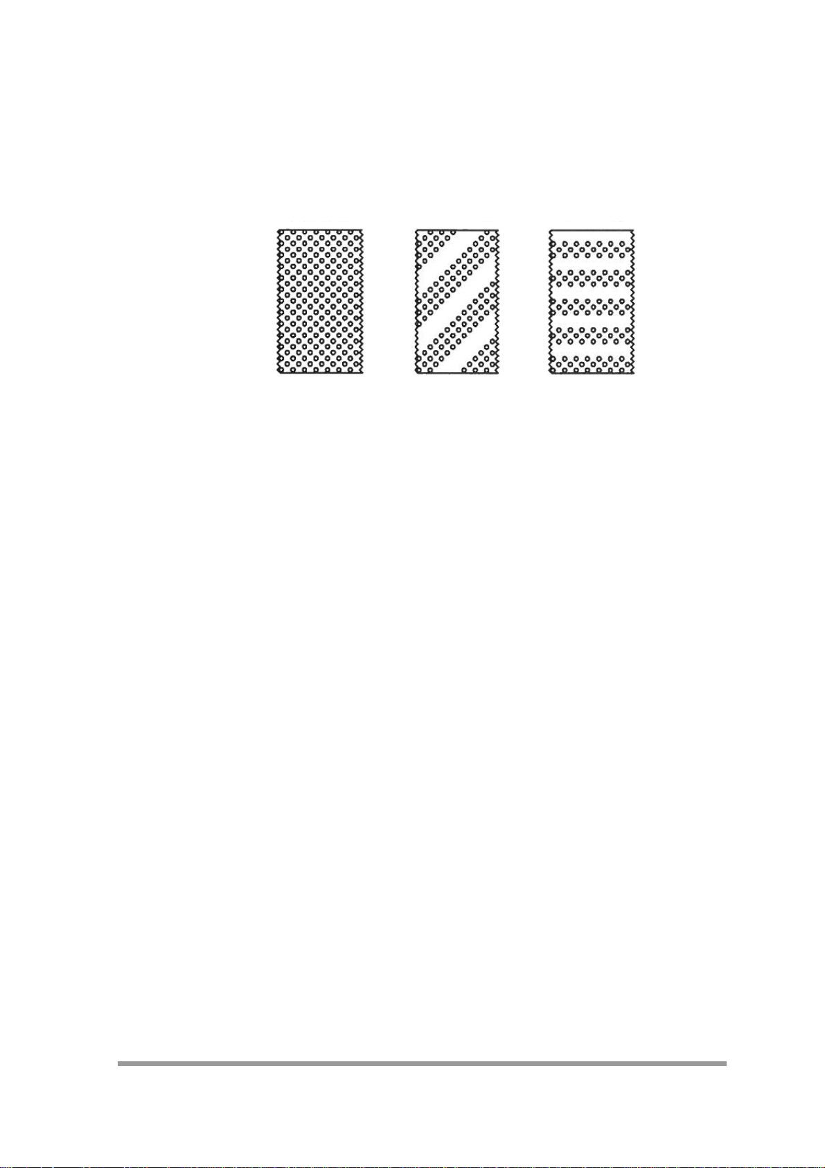
Various bristle materials can be selected for a very large range of
applications. For this, there are two different materials (polyester
and brass) available that are specified in more detail in the technical
data sheet. These are available for selection in three different bristle
patterns (full, spiral-shaped and straight).
Description of the product
Only the same material and bristle pattern type can be used
together. A mixture of different material and bristle pattern is not
intended and must be checked in any individual case.
NOTE
An unfavourably or improperly installed product can disrupt the
conveyor process or contaminate the bulk material to be
transported.
The owner-operator is responsible for taking the required
countermeasures.
In the case of applications with contaminants, Martin Engineering
or one of its representatives can assist with the positioning or with
special solutions.
© Martin Engineering GmbH 8 M3289UK-01/17
Page 11
Description of the product
full trim spiral-shaped straight
3.2 Type clarification
There are three different bristle patterns available in the b rushes for
the product. A selection matrix for usage options is shown in the
appropriate data sheet.
© Martin Engineering GmbH 9 M3289UK-01/17
Page 12

4 Preparing for the installation
4.1 Before the installation
4.1.1 Required materials and tools
No special tools are required for the installation and maintenance of
the product.
4.1.2 Preparatory measures
NOTE
Perform the inspections carefully and completely as described.
The shipping company is liable for any transport damage!
Please contact the shipper with any damage claims.
NOTE
Preparing for the installation
An unfavourably or improperly installed product can disrupt the
conveyor process or contaminate the bulk material to be
transported.
The owner-operator is responsible for taking the required
countermeasures.
In the case of applications with contaminants, please seek the
advice of Martin Engineering or
one of its representatives.
1. Inspect the delivery for the following conditions:
• Is the delivery complete? Does the number of pallets/
crates/containers delivered match the number on th
d
elivery note?
• Do all of the transport packages appear to be undamaged?
Does damage to the packaging exist which indicate
d
amage to the product contained inside?
Always record any incompleteness or transport damage
2.
discovered in the delivery and have it confirmed by the
All damaged p
The delivery should include the following parts, dep
3.
the
scope of the order:
• Brush cleaners incl. two tensioners.
• Two Conveyor Products Warning Labels:
Part no. 23395
• Installation instructions
4. Report any missing or damaged parts to Martin Engineering
one
of its authorised dealers.
roducts must be kept for inspection.
e
s
shipper.
ending on
or
© Martin Engineering GmbH 10 M3289UK-01/17
Page 13
5 Installation
5.1 Safety information
NOTE
Read this section completely before starting any kind of work!
WARNING! RISK OF INJURY!
Body parts and/or clothing may get caught and pulled in by
rotating parts or by the moving conveyor belt.
Before any installation or maintenance work is carried out, ensure
that all power sources to the conveyor belt system and its
accessories are switched off and secured against unauthorised
reactivation. Use warning s igns!
Installation
WARNING! RISK OF EXPLOSION!
Increased risk when using a cutting torch or welding device in
closed rooms!
Check the gas and dust content of the air before usage.
NOTE
The chute wall on which the angular geared motor is installed is
designated in the following as the "operator side". The opposite
chute wall is referred to as the "opposite side".
© Martin Engineering GmbH 11 M3289UK-01/17
Page 14
Installation
5.2 Installation process
5.2.1 Determination of the installation position
The position of the axle and the tensioning device of the secondary
cleaner must be determined on both sides of the chute wall. In this
process, the positions are therefore determined for where the shaft
of the secondary cleaner is routed through the chute wall and/or
where the tensioner is installed on the chute wall.
The secondary cleaner is delivered jointly with a tensioner. This is
delivered as a work´s dismantled unit and will be installed together
with the secondary cleaner during the general installation.
The installation process for the secondary cleaner and the tensioner
is described in the supplied installation instructions.
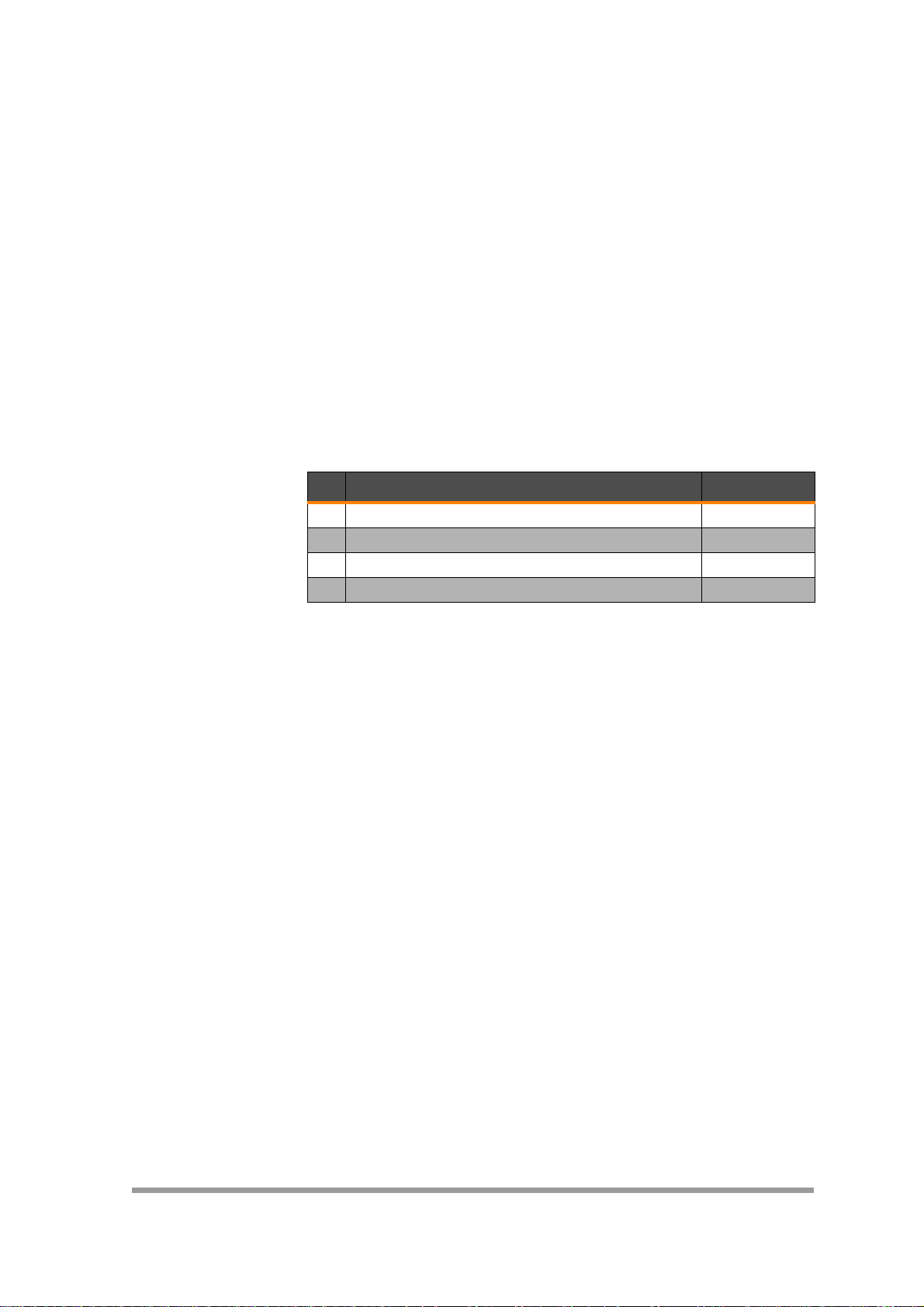
An overview of the installation steps follows:
No. Installation step Instructions
1 Determining the installation position M3289
2 Installing the cleaner M3289
3 Installing the tensioner M3289
4 Tightening the cleaner M3289
Tab. 1:
Various on-site conditions requiring different work steps are
possible for the installation. These are presented as follows:
Installation on an encapsulated transfer system
• Follow the instructions given in Section 5.2.2.
Installation on an encapsulated transfer system with pre-existing
installation openings and air line brackets for belt cleaners.
• Follow the instructions given in Section 5.2.3.
Installation on an open transfer system
• Use the equipment provided at the site to comply with
d
imensions for correct installation.
the
© Martin Engineering GmbH 12 M3289UK-01/17
Page 15

NOTE
Martin Engineering recommends installing a MARTIN® inspection
door for the purpose of better accessibility for maintenance and
repairs.
NOTE
The secondary cleaner should ideally be installed near a head
pulley or a counter-pressure roller. The clearance should not be
more than 200 mm.
NOTE
The installation position is to be so selected that sufficient space is
®
available for the installation of the MARTIN
This distance should lie at least 350 mm outside the chute wall on
the operator side and at least 100 mm on the opposite side.
brush cleaner.
Installation
© Martin Engineering GmbH 13 M3289UK-01/17
Page 16

Installation
90
140
E
13,5
305
180
45
80
R45
min. 50
max. 200
Conveying direction
A
B
C
D
F
Fig. 1:
Pos. Description
A Conveyor belt
B Centre point of the driving drum
C Exit point of the conveyor belt from the driving drum
D Slot
E Installation holes in the tensioner
F Position of the brush ends of the conveyor belt cleaner
© Martin Engineering GmbH 14 M3289UK-01/17
Page 17

1. Deactivate the conveyor system and all accessories before
starting the installation work and secure them against
inadvertent reactivation.
2. Mark the vertical and horizontal centre line of the driving drum
on the operator side of the chute wall to determine the centre
point (B, Fig. 2) of the driving drum. Extend the vertical
centreline to determine the point C.
3. Mark a position (F, Fig. 2) at a distance from 50 to no more than
200 mm in the conveying direction (A, Fig. 2) from the point at
which the belt leaves the head pulley (C, Fig. 2).
4. Draw a vertical line at this position (F, Fig. 2) going downwards
at a right angle to the conveyor belt.
5. Use the dimensions from Figure 2 to mark the installation holes
for the tensioner.
6. Create the slot-shaped cut-out and installation holes as shown
in Figure 2.
7. Repeat steps 1 to 6 on the opposite side of the chute wall.
Installation
© Martin Engineering GmbH 15 M3289UK-01/17
Page 18

Installation
1
5.2.2 Installing the tensioner
Fig. 2:
1. Attach the tensioner (1, Fig. 3) to the chute wall using the
in
stallation holes shown in Fig. 2
2. Repeat step 1 on the opposite side.
© Martin Engineering GmbH 16 M3289UK-01/17
Page 19

5.2.3 Installing the cleaner
1
3
4
2
5
6
WARNING! RISK OF INJURY!
The secondary cleaner is heavy and can cause serious injuries if it
is dropped during lifting or moving.
Always use a suitable lifting device or engage the help of several
persons when lifting the brush cleaner. Do not stand under
hanging loads.
NOTE
Check the oil level in the angled gearbox of the motor before
installing.
Observe the information in the manufacturer's documentation
supplied with the device.
Fix the pillow block (3, Fig. 4) on both sides of the main shaft
1.
(2, Fig. 4) .
Installation
© Martin Engineering GmbH 17 M3289UK-01/17
Fig. 3:
2. Slide the main axle (2, Fig. 4) though the two slots (4, Fig. 4)
chute wall.
3. Secure the pillow blocks (3, Fig.
tensioners (6, Fig. 4).
the
4.
Insert the feather key into the axle, if not already done.
in
4) using the bolts (5, Fig. 4) to
Page 20

Installation
1
2
Fig. 4:
NOTE
Make sure that the feather key (2, Fig. 5) lies in the keyway
(1, Fig. 5) of the axle.
5. Push the angled gearbox motor with mounting plate for motor
torque support (1, Fig. 4) onto the shaft.
NOTE
The mounting plate must be installed from below onto the
tensioner. The angled gearbox motor should always be placed on
the shaft flush with the conveyor belt.
1
2
Fig. 5:
NOTE
The angled gearbox motor (1, Fig. 6) can only be mounted in the
transport direction (2, Fig. 6) on the left side, a changeover to the
right side is not possible.
6. Fix bolts (4, Fig. 4) of the pillow block on both sides with the
nuts.
© Martin Engineering GmbH 18 M3289UK-01/17
Page 21

5.2.4 Electrical connection
Transport direction
Transport direction
Conveyor belt
Cleaning elements
The electrical installation may only be performed by an electrician.
Comply with all laws, standards and directives which are applicable
for the company. Earth the electrical equipment in accordance with
the applicable regulations.
NOTE
Observe instructions in the manufacturer documentation on
making electrical connections!
Observer the installation instructions and wiring diagrams supplied
with the product. The angled gearbox motor must run such that the
cleaning elements move in the opposite
conveyor belt.
Installation
direction to that of the
© Martin Engineering GmbH 19 M3289UK-01/17
Fig. 6:
NOTE
Check the rotational direction of the cleaning elements before
commissioning!
Page 22

Installation
5.2.5 Centring the mainframe beneath the conveyor belt
CAUTION! RISK OF DAMAGE!
Off-track running can cause damage to the conveyor belt edge
and/or the
cleaning elements.
Alignment of the secondary cleaner in accordance with the
following instructions.
NOTE
The following displays are examples and can differ from the
secondary cleaner actually used.
2
1
A
Fig. 7:
Pos. Description
1 Chute wall
2 Driving drum
3 Cleaning elements
Tab. 2: Centring the secondary cleaner beneath the conveyor belt
1. Measure the clearances (A) and (B) between the edge of the
cleaning eleme
nts and the conveyor belt edge.
A
3
NOTE
The conveyor belt must protrude around 50 to 100 mm from the
left and right sides. The cleaning elements must be centrally
aligned beneath the conveyor belt.
© Martin Engineering GmbH 20 M3289UK-01/17
Page 23

If these are not the same, the brush elements will shift on the main
1
2
1
2
axle.
Fig. 8:
Installation
2. Loosen locking collar (1, Fig. 9) and adjusting ring (5,
h sides.
bot
3.
Shift the cleaning elements so that clearance A is equal to
clearance B.
4. Tighten adjusting ring (5, Fig. 9) and securing ring (1,
h sides.
bot
Fig. 9) on
Fig. 9) on
© Martin Engineering GmbH 21 M3289UK-01/17
Page 24

Installation
5.2.6 Aligning the mainframe parallel to the conveyor belt
1
A
4
Fig. 9:
Pos. Description
1 Plan view of cleaning elements
2 Driving drum
3 Driving drum axis
4 Chute wall
Tab. 3: Top view of aligning cleaning elements parallel to conveyor belt
1. Measure the clearance on both sides between the mainframe
and
the head pulley or counter-pressure roller.
A
3
2
NOTE
The measurements must be the same on both sides. If not, the
tensioners must be re-positioned.
© Martin Engineering GmbH 22 M3289UK-01/17
Page 25

5.2.7 Aligning the mainframe horizontally
Installation
1
2
A
4
Fig. 10:
Pos. Description
1 Driving drum
2 Driving drum axis
3 Cleaning elements
4 Chute wall
Tab. 4: Aligning brush cleaner horizontally
1. Align the mainframe horizontally with respect to the head pulley
and
check whether the bristles rest evenly on the conveyor
2.
Tighten the tensioner clamping screws.
A
3
belt.
WARNING! RISK OF INJURY!
The mainframe may not protrude more than 10 mm beyond the
chute wall. Otherwise there is a danger of injury from the rotating
shaft.
The shaft can only be shortened on the drive-facing side and not
on the drive side.
Once the dimensions are correct and the secondary cleaner aligned,
this can be attached accordingly. If this is not the case, then the
mainframe must be reinstalled or repositioned.
© Martin Engineering GmbH 23 M3289UK-01/17
Page 26

Installation
5.2.8 Tensioning the secondary cleaner
NOTE
Perform the following steps carefully so that the MARTIN® brush
cleaner achieves the desired cleaning result.
CAUTION! RISK OF DAMAGE!
Excessive or uneven tightening of the conveyor belt cleaner on the
conveyor belt can cause material damage.
Only adjust conveyor belt cleaner according to specifications and
also ensure that the adjustments on both sides are the same.
NOTE
After the installation, the secondary cleaner must be adjusted to
the conveyor belt. In this, the cleaning elements should not be
pressed more than 3-4 mm against the conveyor belt.
Loosen the clamping screws (1, Fig. 12).
1.
Loosen the lock nut (4, Fig. 12).
2.
Loosen the securing nut (2, Fig. 12).
3.
NOTE
To avoid canting, both tensioners should be moved
simultaneously.
Turn the adjusting screw (3, Fig. 12) anticlockwise till the
4.
cleaning elements are pressed against the conveyor belt.
© Martin Engineering GmbH 24 M3289UK-01/17
Page 27

Installation
1
2
3
4
Fig. 11:
Pos. Description
1 Clamping screw
2 Securing nut
3 Adjusting screw
4 Lock nut
Tab. 5: Description of nuts and screws
5. Repeat working steps on the opposite side.
If the cleaning elements are in the correct position, tighten the
6.
clamping screws (1, Fig. 12
7.
Tighten the securing nut (4, Fig. 12).
8.
Tighten the lock nut (2, Fig. 12).
).
© Martin Engineering GmbH 25 M3289UK-01/17
Page 28

Installation
5.3 Test run
NOTE
Read through this section completely before starting any work on
the belt cleaner or on the customer's conveyor system.
CAUTION! FLYING OBJECTS!
Forgotten tools or installation parts can fall off of the running
conveyor belt and cause minor injuries and property damage.
Always remove any tools from the installation site and conveyor
belt upon completion of the installation work before switching on
the power supply.
WARNING! RISK OF INJURY!
Body parts and/or clothing may get caught and pulled in by
rotating parts or by the moving conveyor belt.
Before any installation or maintenance work is carried out, ensure
that all power sources to the conveyor belt system and its
accessories are switched off and secured against unauthorised
reactivation.
Use warning signs!
1. Thoroughly clean the external chute wall on the operator side
ve the tensioner. Affix Conveyor Products Warning L
abo
(Part No.
by the system operator (also refer to Fig. 13 on page 28).
23395) close to the product where they can be seen
abels
CAUTION! RISK OF DAMAGE!
Never operate the belt cleaner for longer than 15 minutes on the
running, unloaded conveyor belt. A risk of damage due to
overheating exists for the belt cleaner and/or the conveyor belt.
Only operate the belt cleaneron a running and fully loaded
conveyor belt.
2. Remove all tools and fire protection covers from the installati
site an
3.
Perform a 1-hour test run of the conveyor system.
Shut off the conveyor system after the test run, shut off the
4.
power supply and secure it against unauthorised reactivation.
5. Check whether all of the fastening parts are securely tightened.
Tighten a
d the conveyor belt.
ny loose connections.
on
© Martin Engineering GmbH 26 M3289UK-01/17
Page 29

6. Inspect the belt cleaner for the following conditions:
• Wear: a small amount of break-in wear is no
a
s the cleaning elements have adapted to the contou
e conveyor belt, this phenomenon ceases.
th
• Bulk material accumulation: No bulk material ma
a
ccumulate between the cleaning elements and the re
side.
Note the corresponding information in Section 7
7.
“Troubleshooting” in cases of excess wear, bulk material
accumula
tion or other problems.
rmal. As soon
Installation
r of
y
turn
© Martin Engineering GmbH 27 M3289UK-01/17
Page 30

Installation
No. 23395
! WARNING
Body parts and/or clothing may get caught and pulled in by rotating parts
or by the moving conveyor belt. Before any installation or maintenance work
is carried out, ensure that all power sources to the conveyor belt system and its
accessories are switched off and secured against inadvertent reactivation.
Use warning signs!
5.4 Placement of warning labels and warning tags
© Martin Engineering GmbH 28 M3289UK-01/17
Fig. 12:
Page 31

6 Maintenance
6.1 Safety information
NOTE
Maintenance inspections must be performed at least once a week.
Shorter maintenance intervals may be required depending on the
operating conditions.
NOTE
Read this section completely before starting any kind of work.
WARNING! RISK OF INJURY!
Body parts and/or clothing may get caught and pulled in by
rotating parts or by the moving conveyor belt.
Shut off the power supply to the conveyor system and its
accessories and secure it against unauthorised reactivation before
performing any maintenance work.
Use warning signs!
Maintenance
6.2 Weekly maintenance
1. Shut off the power supplies of the conveyor belt and any
add
itional equipment and secure them against unautho
reactivatio
2.
Remove all material deposits from the cleaning elements a
the
mainframe.
3.
Inspect whether all of the fastening parts are secure
tightene
4.
Check the cleaner tension and re-tighten if necessary.
Check the cleaning elements for wear, damage and missing
5.
parts.
n.
d. Tighten any loose con
NOTE
Check wear and adjustments once a month, adjust if necessary.
The cleaning elements must always make sufficient contact with
the conveyor belt.
rised
nd
ly
nections.
© Martin Engineering GmbH 29 M3289UK-01/17
Page 32

Maintenance
NOTE
Take the corresponding parts out of service if any indications of
functional disturbances are noticed. Contact Martin Engineering or
one of its representatives for support. Do NOT start up the
conveyor system until the cause of the problems has been
recognised and eliminated.
CAUTION! RISK OF DAMAGE!
Cleaning elements may not abrade under the height of the fixing
screws on the shaft or must still have at least an outer diameter of
90 mm, otherwise this can lead to serious material damage.
Inspect cleaning elements regularly and replace in time!
6. If the cleaning elements have a diameter of less than 90 mm,
the
se must be replaced in accordance with the instructio
Section 6
7.
Clean all the warning labels. Replace illegible warn
imme
Engineering or a
.3.
diately. Warning labels can be purchased from
contracted dealer.
ns in
ing labels
Martin
CAUTION! FLYING OBJECTS!
Forgotten tools or installation parts can fall off of the running
conveyor belt and cause minor injuries and property damage.
Always remove any tools from the installation site and conveyor
belt upon completion of the installation work before switching on
the power supply.
NOTE
The angled gearbox motor must be checked at least once a
month for oil level, oil change, leaks, etc. Observe instructions in
the manufacturer documentation on maintenance intervals!
NOTE
The bearing of the angled gearbox motor must be checked at least
once a week for lubrication, damage, running performance, etc.
Observe the information in the manufacturer's documentation
supplied with the device!
© Martin Engineering GmbH 30 M3289UK-01/17
Page 33

NOTE
The bearings are lubricated for continuous operation, and relubrication is not absolutely necessary. The bearings may need to be
relubricated under extreme conditions such as high temperatures,
temperature fluctuations and high dust exposure.
For example, the grease Arcanol MULTI2 (lithium soap on mineral
oil basis, viscosity at 40 °C >= ISO VG 68 mm²/s) can be used for
relubrication. This grease is suitable for temperatures from -30 °C
to +120 °C, or 75 °C continuous temperature. Refer to the corresponding documentation of the pillow blocks for additional information.
Relubrication intervals and quantities need to be defined as needed. The manufacturer specifies 60,000 h for speeds under
200 rpm.
8. Remove all tools from the working area.
9.
Switch on the conveyor system.
WARNING! RISK OF INJURY!
Body parts and/or clothing may get caught and pulled in by
rotating parts or by the moving conveyor belt.
Do not touch or reach into the conveyor system or its accessories
during operation.
Maintenance
10. Observe the brush cleaner and check its cleaning performance.
6.3 Replacement of the cleaning elements
WARNING! RISK OF INJURY!
Body parts and/or clothing may get caught and pulled in by
rotating parts or by the moving conveyor belt.
Before any installation or maintenance work is carried out, ensure
that all power sources to the conveyor belt system and its
accessories are switched off and secured against unauthorised
reactivation. Use warning s igns!
© Martin Engineering GmbH 31 M3289UK-01/17
Page 34

Maintenance
1
2
3
4
6.3.1 Lowering of secondary cleaner
The secondary cleaner must be lowered before carrying out
maintenance work or before de-installation.
The following steps are necessary for this:
1.
Loosen the clamping screws (1, Fig. 14
2.
Loosen the lock nuts (2, Fig. 14).
3.
Loosen the securing nuts (4, Fig. 14).
).
Fig. 13:
Pos. Description
1 Clamping screw
2 Securing nut
3 Adjusting screw
4 Lock nut
Tab. 6: Description of nuts and screws
© Martin Engineering GmbH 32 M3289UK-01/17
Page 35

4. Turn adjusting screw (3, Fig. 14) in the clockwise direction to
lo
wer the brush clea
ner.
NOTE
Lower the MARTIN® brush cleaner so that the cleaning elements
no longer touch the conveyor belt.
5.
Repeat working steps on the opposite side.
Maintenance
© Martin Engineering GmbH 33 M3289UK-01/17
Page 36

Maintenance
6.3.2 Replace cleaning elements
CAUTION! RISK OF INJURY!
The angled gearbox motor can be turned out of the way during the
dismantling.
Secure angled gearbox motor before dismantling.
NOTE
The old and new cleaning elements should always be the same
(material and pattern type).
Disconnect the power cable from the angled gearbox motor
1.
(if necessary).
Pull the angled gearbox motor (1, Fig. 15) off the shaft of
2.
secon
appropriately.
dary cleaner and lay it on a level, firm surface or se
the
cure
NOTE
Make sure that the electrical power cable does not remain hanging
and is not subjected to any mechanical strain. Secure
appropriately if the power cable has not been removed.
© Martin Engineering GmbH 34 M3289UK-01/17
Page 37

Maintenance
1
3
4
2
1
2
Fig. 14:
3. Loosen the bolts from both sides of the pillow block (3, Fig. 15)
and
pull it and the main shaft with the pillow blocks from t
chute.
Fig. 15: De-installation of the cleaning elements
Loosen screws in the locking ring (1, Fig. 16) and
4.
adjust
ment ring for the zigzag system (2, Fig. 16) at
pull off from th
and
e main shaft.
the
he
one side
© Martin Engineering GmbH 35 M3289UK-01/17
Page 38

Maintenance
1
Fig. 16:
5. Worn cleaning elements (1, Fig. 17) can now be replaced.
6. Install the secondary cleaner as in Section “Installin
cleane
r”.
g the
© Martin Engineering GmbH 36 M3289UK-01/17
Page 39

7 Troubleshooting
7.1 Safety information
NOTE
The product is exposed to many different types of bulk materials
and is often used under extreme operating and environmental
conditions. Malfunctions other than those listed below can
therefore occur.
In this case, either Martin Engineering or one of its representatives
can assist with the positioning or with special solutions. Do not
start up the conveyor system again until the fault has been
recognised and cleared.
7.2 Troubleshooting
Check the following items if excessively high wear on the cleaning
elements and/or unsatisfactory cleaning performance is noticed
following installation:
Troubleshooting
Symptom Cause Remedy
High wear on the
cleaning elements,
noise or vibration.
Inadequate cleaning
effect.
Tab. 7: Troubleshooting
The cleaner is too heavily
loaded.
The cleaner loading is too
lightly set.
Too high operating
temperature.
Cleaning elements do not
rotate with the rest.
Cleaning performance
inadequate due to high dirt
accumulation.
Cleaning elements are
worn.
Reduce the tension in the tensioner
(see Section 5.2.8).
Increase the pre-tension of the
tensioner. Die bristles of the
cleaning elements must be bent by
approx. 3-4 mm at the conveyor
belt.
The MARTIN
be used in the temperature range
0° C to +100° C.
Cleaning elements are not fixed to
the shaft; check fixing elements.
(zigzag system)
Install a pre-cleaner as an extra.
Renew cleaning elements, as
described in Section 6.3.2.
®
brush cleaner can
© Martin Engineering GmbH 37 M3289UK-01/17
Page 40

Troubleshooting
Symptom Cause Remedy
Unusual noises of
cleaning results.
Excessive
accumulation of
material
Uneven wear of the
cleaning elements
Motor gets hot, does
not rotate.
Maintenance intervals have
not been observed.
Wrong direction of rotation
of the angled gearbox
motor.
Impacts, conveyor belt
vibration. Motor imbalance,
heavy dirt on the cleaning
elements.
The cleaner loading is too
lightly set.
Cleaning elements have
increased material residues.
Cleaning elements are not
evenly arranged under the
conveyor belt.
Cleaning elements are not
centred on the belt loading.
Cleaning width too small.
Shaft touches the frame,
setting too high, brush
cleaner badly aligned.
Fibres on the brush or in the
bearing, bristles filled with
bulk material.
The angled gearbox motor must be
maintained at intervals of 10,000
working hours in accordance with
the documentation supplied.
The angled gearbox motor must
rotate in the direction opposite to
that of the conveyor belt.
Brush cleaner installed too far from
head pulley or return idler
removed. Align shaft to gearbox.
Wrong cleaning elements used.
Reduce the set distance of the
cleaning elements to the conveyor
belt.
Install cleaning elements of a
different trim type.
Align the brush cleaner horizontally
to the conveyor belt.
Check alignment, installation.
Adjust cleaning width.
Check and correct alignment,
installation; wrong brush type.
Tab. 7: Troubleshooting
© Martin Engineering GmbH 38 M3289UK-01/17
Page 41

8 Storage, de-installation, disposal
8.1 Packing and transportation
The products described here are packed and shipped by Martin
Engineering.
The products may be transported solely in the Martin Engineering
packaging.
The logistics company in charge of the shipment shall be
responsible for any damage and/or loss.
8.2 Storage
To ensure optimal function of the product, Martin Engineering
recommends storing its components in a dry place at room
temperature where they are protected against direct sunlight.
The best storage conditions are at temperatures ranging from +0 °C
to +30°C and 60% relative humidity.
Storage, de-installation, disposal
Martin Engineering guarantees that the stored products will remain
fully functional for at least 2 years under the storage conditions
specified here.
8.3 De-installation
The de-installation is carried out in the reverse order to that of the
installation (see Section 5.2.2, page 15).
8.4 Disposal
Assemblies and/or single parts of the Martin Engineering products
must be professionally disposed of after usage as follows.
• Complete assemblies must be dismantled, sort
material type, a
Comply with all nationally and internationally applicable disposal
regulations when disposing of the product.
ed by
nd separately disposed of.
© Martin Engineering GmbH 39 M3289UK-01/17
Page 42

9 Part numbers
Part numbers
This section lists the product designations with their associated part
numbers for the MARTIN
accessories.
Please always indicate the part numbers in every order.
®
Brush Cleaner system and its
9.1 Explanation of part numbers
Martin®Brush Cleaner
41580-aabccddeeffg-hh
a Belt width in inches
b Brush pattern version
F: Full
S: Spiral-shaped
L: Straight
c Bristle material
PB: Polyester (PBT)
BR: Brass
d Cleaning width in inches
e Main shaft material
MS: Mild steel (1.0037)
A2 Stainless steel (1.4031)
fVoltage (V)
11: 110
23: 230
40: 400
46: 460
g Frequency in Hertz
5: 50
6: 60
h Further options
X: Is simply incremented
9.2 MARTIN
With standard rubber door, up to 68 °C:
© Martin Engineering GmbH 40 M3289UK-01/17
®
Inspection doors
• 229 x 305 mm: Part no. CYAR-0912M.
• 305 x 356 mm: Part no. CYAR-1214M.
• 305 x 457 mm: Part no. CYAR-1218M.
• 457 x 610 mm: Part no. CYAR-1824M.
• 610 x 610 mm: Part no. CYAR-2424M.
Page 43

Part numbers
9.3 Installation manuals
9.4 Warning labels / Warning tags
9.5 Accessories and options
9.5.1 Inspection doors
• Martin® Inspection Door: Publication no. M3127.
• Conveyor Products Warning Label:
Part no. 23395
When installing the
transfer system, a MARTIN
improved accessibility during inspection and maintenance. This can
be purchased from Martin Engineering or a contracted dealer.
9.5.2 Cleaning elements
The cleaning elements for the
in various material and trim versions. The appropriate type of
material and trim is selected depending on the working conditions
(bulk material, temperature etc.). Please take further specifications
from the appropriate data sheet of the
L3863.
MARTIN
®
Brush Cleaner on an encapsulated
®
Inspection Door is recommended for
MARTIN
®
Brush Cleaner are available
MARTIN
®
Brush Cleaner
© Martin Engineering GmbH 41 M3289UK-01/17
Page 44

9.6 Martin®Brush Cleaner
11
13
12
1
8
Part numbers
2
4
5
10
9
3
7
6
OL
35
Fig. 17:
CW
IL
422
min. 503 /
max. 633
140
13,5
90
© Martin Engineering GmbH 42 M3289UK-01/17
Page 45

Part numbers
Item /
Pos.
11
2 1 Mainframe / Hauptachse 41581-18
3 2 Bearing pillow block / Stehlager-Gehäuseeinheit 41584-035-A
Qty /
Anz.
Description / Beschreibung P/N / Teile-Nr.
Spiroplan-Angle-Gearmotor / SpiroplanWinkelgetriebemotor
41582-XXX
4
52
62
7
81
91
10 2 Locking ring / Sicherungsring 41593-035-A
11 4
12 4
13 4
s.C. /
s.T.
2 Bearing mounting console / Lager Montagekonsole 41591
Spiral brush edging zick-zack system / Spiralbürste
Besatz Zick-Zack System
Fixing collar for Zick-Zack System / Stellring ZickZack System
Tensioner for Brush Cleaner / Spannvorrichtung für
Bürstenreiniger
Support plate for engine torque arm /
Aufnahmeblech für Motor-Drehmomentstütze
Feather keys DIN 6885-A, 6 x 6 x 70 mm /
Passfeder
HHC screw M6 x 20 - DIN 933, (1.0032) galv. /
Sechskantschraube
Washer flat M6 - DIN 125 A, (1.0032) galv. /
Unterlegscheibe
Washer spring M6 - DIN 127, (1.0032) galv. /
Federring
s.C. / s.T.
41587-035
41589-A
41592-A
41588-A-06-06-70
41081-06020BZP88
41088-06AZP
41090-06AZP
© Martin Engineering GmbH 43 M3289UK-01/17
Page 46

DIM
Part number /
Teilenummer
41580-18XXX12XXXXX-00 12 300 1000 1382 41581-18XXX 3
41580-24XXX20XXXXX-00 20 500 1150 1532 41581-24XXX 5
41580-30XXX24XXXXX-00 24 600 1300 1682 41581-30XXX 6
41580-36XXX28XXXXX-00 28 700 1450 1832 41581-36XXX 7
41580-42XXX36XXXXX-00 36 900 1600 1982 41581-42XXX 9
41580-48XXX40XXXXX-00 40 1000 1750 2132 41581-48XXX 10
41580-48XXX43XXXXX-00 43 1100 1750 2132 41581-48XXX 11
41580-54XXX47XXXXX-00 47 1200 1900 2282 41581-54XXX 12
41580-60XXX51XXXXX-00 51 1300 2050 2432 41581-60XXX 13
41580-66XXX59XXXXX-00 59 1500 2200 2582 41581-66XXX 15
CW
IL OL 1 4
[inch] [mm]
PN Item /
Teilenr. Pos.
Qty. Item /
Anz. / Pos.
Part numbers
41580-72XXX63XXXXX-00 63 1600 2350 2732 41581-72XXX 16
41580-78XXX71XXXXX-00 71 1800 2400 2882 41581-78XXX 18
© Martin Engineering GmbH 44 M3289UK-01/17
Page 47

Part numbers
Part number /
Teilenummer
41580-XXXXXXXMSXXX-00 41581-XXMS
41580-XXXXXXXA2XXX-00 41581-XXA2
PN Item /
Teilenr. Pos.
1
Part number /
Teilenummer
41580-XXXXXXXXX11X-00 41582-11X
41580-XXXXXXXXX23X-00 41582-23X
41580-XXXXXXXXX40X-00 41582-40X
41580-XXXXXXXXX46X-00 41582-46X
Part number /
Teilenummer
41580-XXXPBXXXXXXX-00 41586-10PBX
41580-XXXBRXXXXXXX-00 41586-10BRX
Part number /
Teilenummer
PN Item /
Teilenr. Pos.
2
PN Item /
Teilenr. Pos.
4
PN Item /
Teilenr. Pos.
4
Part number /
Teilenummer
41580-XXXXXXXXXXX5-00 41582-XXX5
41580-XXXXXXXXXXX6-00 41582-XXX6
Type of brush pattern /
Ausführung des
Bürstenbesatzes
PN Item /
Teilenr. Pos.
2
41580-XXFXXXXXXXXX-00 41586-10XXF Full seat / Voll
41580-XXSXXXXXXXXX-00 41586-10XXS
41580-XXLXXXXXXXXX-00 41586-10XXL Linear / Linear
© Martin Engineering GmbH 45 M3289UK-01/17
Spiral /
Spiralförmig
Page 48

9.6.1 Technical Specification Angular Gear Motor
• Operating voltage 110V-460V at 50/60 Hz 4-pole
(special voltages possible on request).
• Output: 0.55 kW
• Current consumption: 1.55 A at 400V/50Hz
• Ingress protection: IP55
• Protection class: ISO-F
• Speed: 135 rpm 50 Hz
• Peripheral speed: 0.4 m/s @ 50 Hz
• Operating temperatures: -20°C to +60°C
Part numbers
© Martin Engineering GmbH 46 M3289UK-01/17
Page 49

10 Declaration of Incorporation
Declaration of incorporation in accordance with
Machinery Directive (2006/42/EG)
Annex II B for the installation of an incomplete machine
We, Martin Engineering,
In der Rehbach 14 Tel.: +49 6123-97820
D-65396 Walluf Fax: +49 6123-75533
herewith declare that the product named in the following
Product designation:
Declaration of Incorporation
Conveyor belt cleaner
of make / type:
MARTIN
with serial number:
meets the following requirements:
Machinery Directive 2006/42/EC
DIN EN 618 - Equipment and systems for bulk materials
DIN/EN 1083-1; -2 Power-driven brushes
The following harmonised standards were particularly applied:
DIN EN ISO 12100 Safety of Machinery
Notified authority:
The installation instructions belonging to the product and the technical documentation are
enclosed with the product in their original version.
The commissioning of this product is prohibited until it has been determined that the system in
which it is to be installed meets the requirements of versions 98/37/EC and 2006/42/EC of the
EC Directive.
®
Brush Cleaner
not required
not required
Date: 21/01/2010
Manufacturer's signature: Managing director, Michael Hengl
© Martin Engineering GmbH 47 M3289UK-01/17
Page 50

PROBLEM SOLVED
™
Publication no. M3289UK-01/17 ©MARTIN ENGINEERING 2015
USA (Headquarters)
Martin Engineering
One Martin Place, 61345 Neponset (Illinois), USA
Tel. +1 (800) 544-2947; Fax +1 (800) 814-1553
info@martin-eng.com; www.martin-eng.com
European subsidiaries
Germany (Main European branch)
Martin Engineering GmbH
In der Rehbach 14, 65396 Walluf, Germany
Tel. +49 6123 97820; Fax +49 6123 75533
info@martin-eng.de; www.martin-eng.de
Great Britain
Martin Engineering Ltd.
8, Experian Way, NG2 Business Park,
Nottingham NG2 1EP, Nottinghamshire, Great Britain
Tel. +44 115 946 4746; Fax +44 115 946 5550
info@martin-eng.co.uk; www.martin-eng.co.uk
France
Martin Engineering SARL
50 Avenue d‘Alsace, 68025 Colmar Cedex, France
Tel. +33 389 20 63204; Fax +33 389 20 4379
info@martin-eng.fr; www.martin-eng.fr
Russia
OOO Martin Engineering
Ul. Bolshaya Dmitrovka, 23/1
125009 Moscow, Russia
Tel +7 495 181 33 43; Fax +7 499 720 62 12
info@martin-eng.ru; www.martin-eng.ru
Turkey
Martin Engineering Makina Sanayi ve
Ticaret Ltd.Sti
Yukari Dudullu Imes Sanayi Sitesi, B Blok 205 Sokak No.6
34775 Ümraniye Istanbul, Turkey
Tel. +90 216 4993 491; Fax +90 216 4993 490
info@martin-eng.com.tr; www.martin-eng.com.tr
Italy
Martin Engineering Italy Srl
Via Buonarroti, 43/A, 20064 Gorgonzola (MI), Italy
Tel. +39 295 3838 51; Fax +39 295 3838 15
info@martin-eng.it; www.martin-eng.it
Quality management system certified by DNV - ISO 9001
Subject to technical modifications
 Loading...