

Page 1
martinarchitectural
l
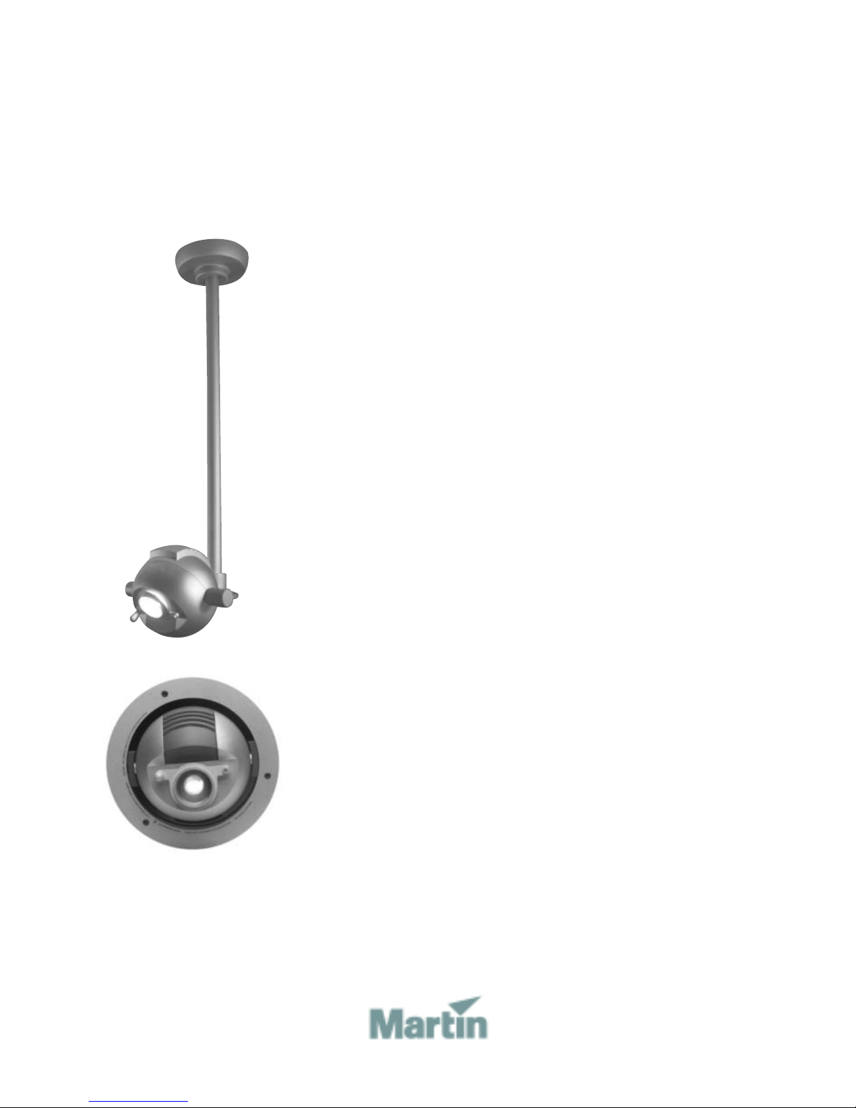
Alien 05
user manua
Page 2
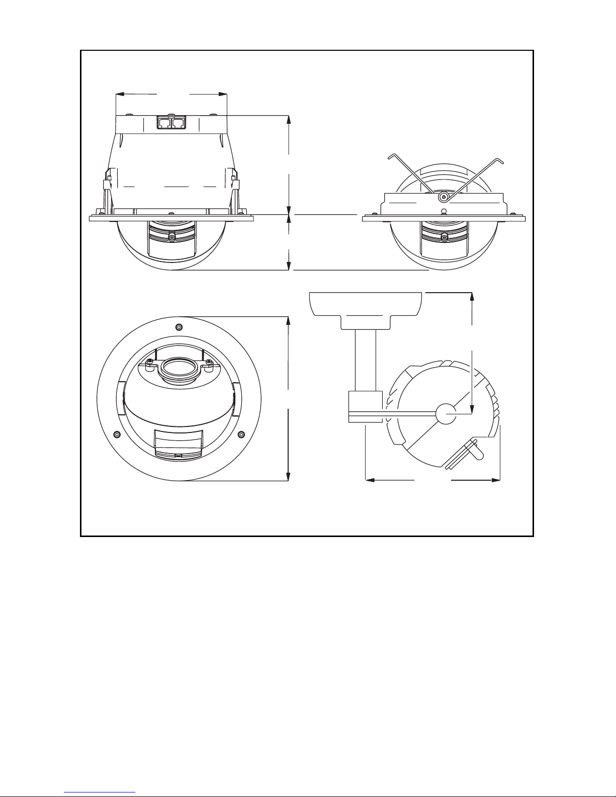
Measurements are in millimeters
150 / 600
Alien 05 Recessed
132
Alien 05 Eyeball
118
65
195
150 / 600
170
Alien 05 Stem Mount
© 2002-2005 Martin Professional A/S, Denmark.
All rights reserved. No part of this manual may be reproduced, in any form or by an y means , with-
out permission in writing from Martin Professional A/S, Denmark.
Printed in Denmark.
P/N 35000104, Rev G
Page 3

Introduction . . . . . . . . . . . . . . . . . . . . . . . . . . . . . . . . . . . . . . . . 4
Safety information . . . . . . . . . . . . . . . . . . . . . . . . . . . . . . . . . . . . . . . . . . . . 4
Configuring an Alien 05 system. . . . . . . . . . . . . . . . . . . . . . . . 6
Control network cabling . . . . . . . . . . . . . . . . . . . . . . . . . . . . . . . . . . . . . . . . 7
AC power . . . . . . . . . . . . . . . . . . . . . . . . . . . . . . . . . . . . . . . . . . . . . . . . . . .9
Orientation in up-light installations. . . . . . . . . . . . . . . . . . . . . . . . . . . . . . . 12
Installing an Alien 05 Recessed. . . . . . . . . . . . . . . . . . . . . . . 13
Fixture location. . . . . . . . . . . . . . . . . . . . . . . . . . . . . . . . . . . . . . . . . . . . . .13
Prerequisites . . . . . . . . . . . . . . . . . . . . . . . . . . . . . . . . . . . . . . . . . . . . . . .14
Mounting hole. . . . . . . . . . . . . . . . . . . . . . . . . . . . . . . . . . . . . . . . . . . . . . . 15
Connection and mounting . . . . . . . . . . . . . . . . . . . . . . . . . . . . . . . . . . . . .15
Removing the Alien 05 Recessed . . . . . . . . . . . . . . . . . . . . . . . . . . . . . . . 16
Installing an Alien 05 Eyeball. . . . . . . . . . . . . . . . . . . . . . . . . 17
Fixture location. . . . . . . . . . . . . . . . . . . . . . . . . . . . . . . . . . . . . . . . . . . . . .17
Prerequisites . . . . . . . . . . . . . . . . . . . . . . . . . . . . . . . . . . . . . . . . . . . . . . .18
Install the network . . . . . . . . . . . . . . . . . . . . . . . . . . . . . . . . . . . . . . . . . . .18
Connecting and mounting an Alien 05 Eyeball . . . . . . . . . . . . . . . . . . . . . 19
Installing an Alien 05 Stem Mount. . . . . . . . . . . . . . . . . . . . . 21
Fixture location and orientation . . . . . . . . . . . . . . . . . . . . . . . . . . . . . . . . . 21
Prerequisites . . . . . . . . . . . . . . . . . . . . . . . . . . . . . . . . . . . . . . . . . . . . . . .21
Connecting and mounting Alien 05 Stem Mount . . . . . . . . . . . . . . . . . . . . 22
General operation . . . . . . . . . . . . . . . . . . . . . . . . . . . . . . . . . . 31
Prolonging lamp life . . . . . . . . . . . . . . . . . . . . . . . . . . . . . . . . . . . . . . . . . . 31
Positioning the beam . . . . . . . . . . . . . . . . . . . . . . . . . . . . . . . . . . . . . . . . . 31
Diffuser lens . . . . . . . . . . . . . . . . . . . . . . . . . . . . . . . . . . . . . . . . . . . . . . . .33
Color filters. . . . . . . . . . . . . . . . . . . . . . . . . . . . . . . . . . . . . . . . . . . . . . . . . 33
Control . . . . . . . . . . . . . . . . . . . . . . . . . . . . . . . . . . . . . . . . . . . . . . . . . . . . 34
Service . . . . . . . . . . . . . . . . . . . . . . . . . . . . . . . . . . . . . . . . . . . 35
Replacing the lamp . . . . . . . . . . . . . . . . . . . . . . . . . . . . . . . . . . . . . . . . . .35
Removing the diffuser filter . . . . . . . . . . . . . . . . . . . . . . . . . . . . . . . . . . . . 38
Replacing color filters. . . . . . . . . . . . . . . . . . . . . . . . . . . . . . . . . . . . . . . . .39
Troubleshooting . . . . . . . . . . . . . . . . . . . . . . . . . . . . . . . . . . . 43
Specifications . . . . . . . . . . . . . . . . . . . . . . . . . . . . . . . . . . . . . 44
3
Page 4

Introduction
Thank you for selecting the Martin Alien 05. The Alien 05 is a series of color
changers with eight interchangeable dichroic color filters (plus open white)
and speed change control. The Alien 05’s adjustable spherical head can be
angled and swiveled.
Alien 05 luminaires have a beam angle is 55-degrees and a long-life 3000
hour lamp is included. Alien 05s are dimmable when an appropriate
transformer is used.
Safety information
Warning! This product is not for household use.
1
This product presents risks of lethal or severe injury due to fire and heat,
electric shock, ultraviolet radiation, and falls. Read this manual before
powering or installing the fixture, follow the safety precautions listed below
and observe all warnings in this manual and on the fixture. If you have
questions about how to operate the fixture safely, please contact your Martin
dealer or call the Martin 24-hour service hotline at +45 70 200 201.
Safety during installation and maintenance
• Do not install the fixture outdoors.
• When installing the fixture above ground level, verify that the structure can
hold the weight of all installed devices.
• Block access below the work area whenever installing or removing the
fixture.
• Disconnect the fixture from AC power before removing or installing the
lamp, fuses, or any part.
• Use only a source of AC power that complies with local building and
electrical codes and has both overload and ground-fault protection.
• When replacing the lamp, allow the fixture to cool for at least 15 minutes
before opening the fixture.
• Do not modify the fixture or install other than genuine Martin parts.
• Refer all service to a Martin service technician.
4Introduction
Page 5

Safety during operation
• Never operate the fixture with missing or damaged lenses and/or covers.
• Do not stare directly into the light. Never look at an exposed lamp while it is
lit.
• Replace the lamp if it becomes defective or worn out.
• Do not illuminate surfaces within 0.5 meters (20 inches) of the fixture.
• Never place filters or other materials over the lens.
• The exterior of the sphere becomes very hot, up to 90° C (194° F) during
normal operation. Do not locate the fixture in areas where accidental contact
is likely.
• Do not operate the fixture if the ambient temperature (Ta) exceeds 40° C
(104° F).
Introduction 5
Page 6
Configuring an Alien
05 system
The Alien 05 Series is made up of the following products:
05 Driver
Alien 05
Recessed
Alien 05
Eyeball
Alien 05 Stem
Mount
Contains the intelligent control functions, and a mains
power relay. Every Alien 05 system must have at
least one 05 Driver. An 05 Driver can control up to 24
Alien 05 luminaires (of all models).
Recessed ceiling or wall luminaires for use outside of
the United States.
Recessed ceiling or wall luminaires for use in the
United States. Designed for mounting in a Cooper
Lighting, Halo brand, recessed, low-volt, non-IC
fixture housing (item # H7LVT).
Arm-mounted luminaires that are designed to be
hung from a ceiling. Several arm lengths and bases
(with built-in dimmable transformers) are available.
2
05 Repeater
Oracle
Note that in this document we refer to Alien 05 Recessed, Alien 05 Eyeball
and Alien 05 Stem Mount models collectively as “Alien 05” luminaires.
The following sections in this chapter describe rules and concepts needed
to design and implement an Alien 05 installation - specifically regrading data
and power.
A signal amplifier that enables more than 24 Alien 05
luminaires to be controlled from a single 05 Driver.
A dedicated control unit for the Alien 05 series.
6 Configuring an Alien 05 system
Page 7
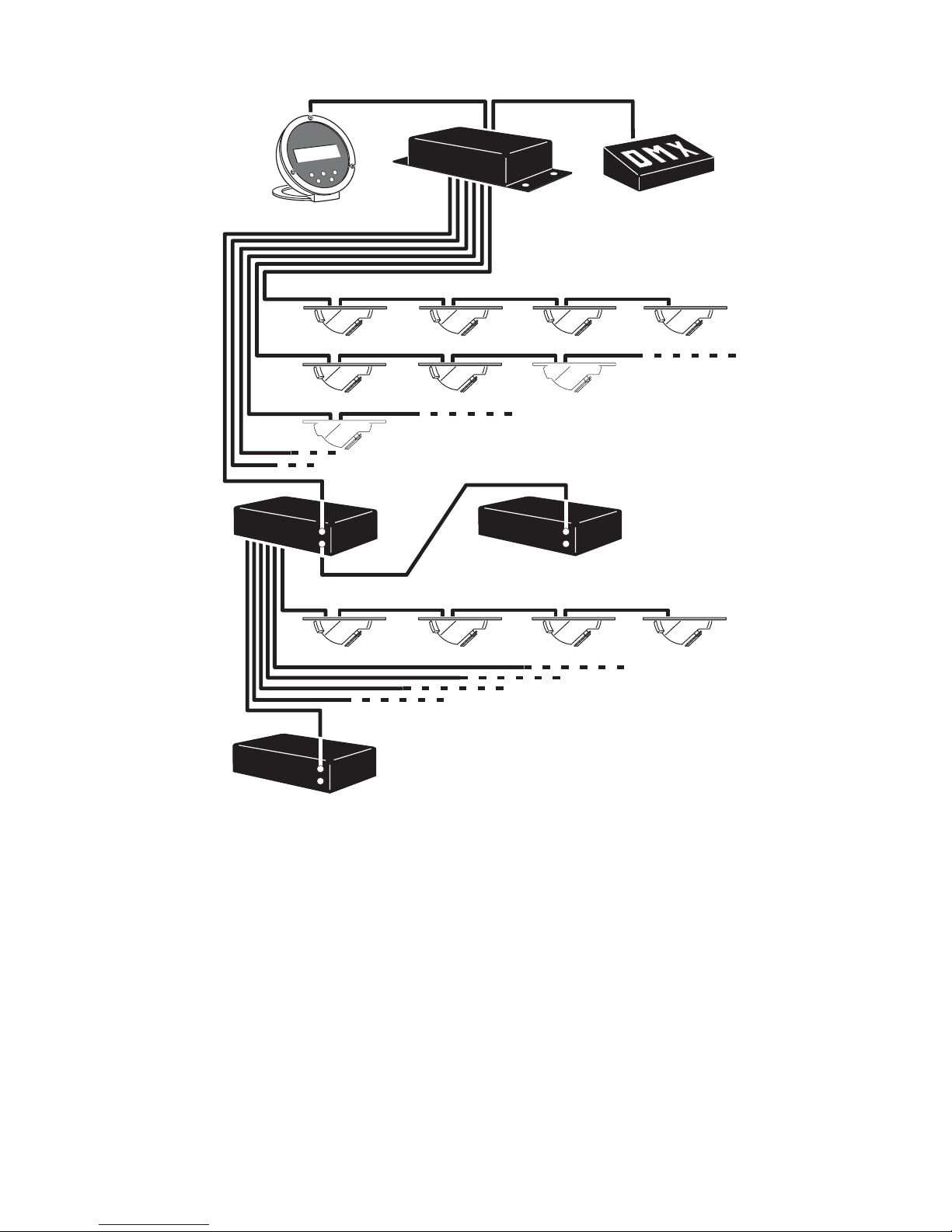
Control network cabling
An Alien 05 must be connected to an 05 Driver unit (directly, or indirectly via
an 05 Repeater unit) that contains the intelligent control functions. The 05
Driver transmits commands to the Alien 05 luminaires via CAT5 network
cables (also available separately).
Each 05 Driver unit has six independent control channels, to each of which
a single 05 Repeater, or up to four Alien 05s can be connected (in a daisychain). Each 05 Driver channel can provide an individual program - with
different effects - to the Alien 05s connected to that channel. All the fixtures
on one channel will mimic each other in their behavior.
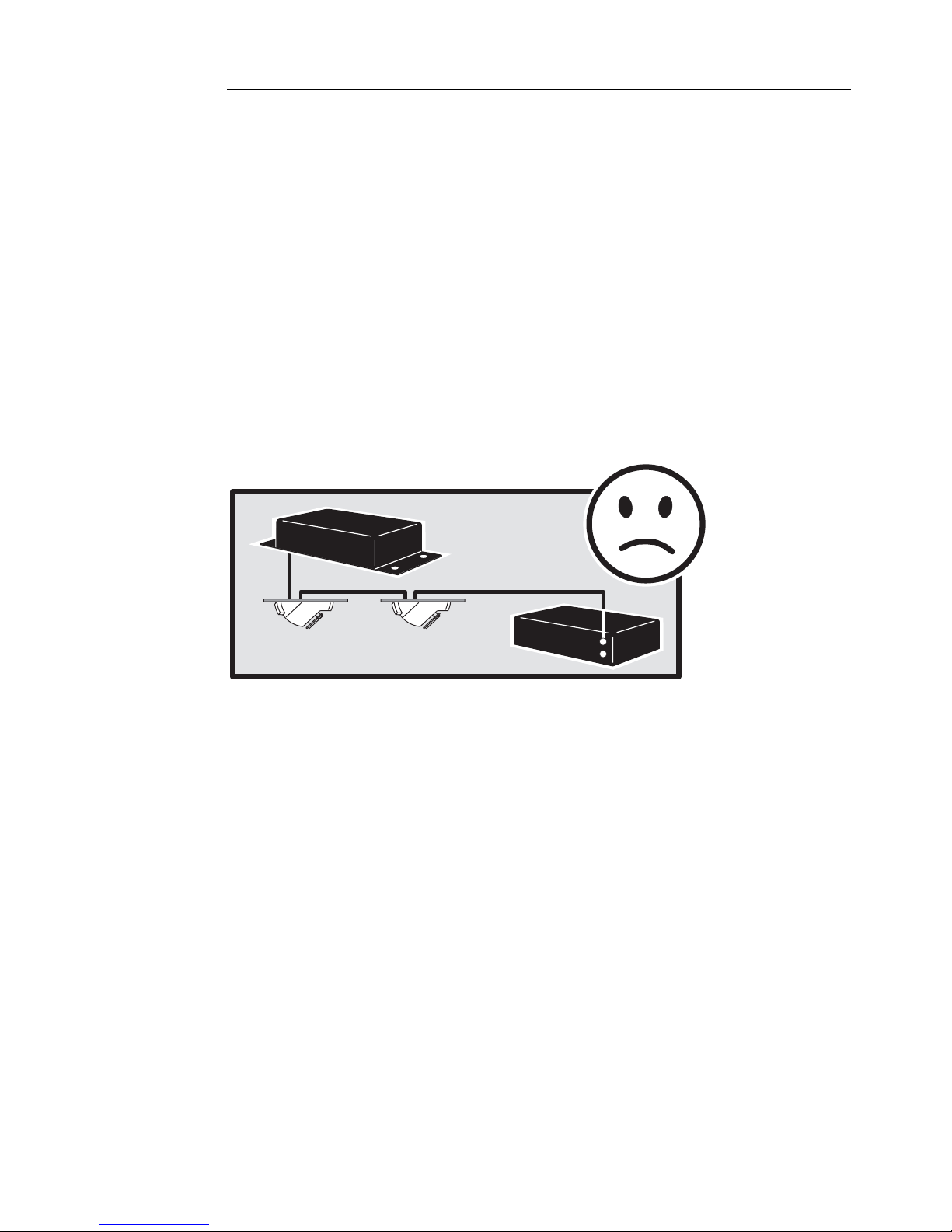
Warning: Do not mix Alien 05 luminaries and 05 Repeaters on the same
Output link. Connect only Alien 05 luminaires, or only a Alien
05, to an individual connector. This applies to both the 05 Driver
and the 05 Repeater.
Driver
Repeater
Note: The maximum control network cable run between the 05 Driver
or 05 Repeater and the last connected Alien 05 is 40 meters (131
Configuring an Alien 05 system 7
Page 8
ft.) Solid or stranded cable may be used; see page 44 for
specifications.
Oracle
Repeater
Driver
DMX control device
Alien 05 luminaires
Repeater
Repeater
Laying control network cables
Lay network cables from as many of the 05 Driver’s, or 05 Repeater’s, six
output channel sockets as is necessary to the Alien 05 mounting positions.
Start with the locations closest to the 05 Driver or 05 Repeater.
If you are connecting multiple Alien 05s in daisy chains, run cables from the
first positions in the chain to the next ones. In this way you will connect the
first Alien 05 luminaire to the second Alien 05 luminaire, the second
luminaire to the third, and the third to the fourth. The connection order is not
important but keep the cable run from any single 05 Driver or 05 Repeater to
the last luminaire in its chain of connected luminaires to less than 40 meters
(131 ft.). The cable sockets on the Alien 05s are identical: either one may be
used for input.
8 Configuring an Alien 05 system
Page 9
AC power
Each Alien 05 draws 50 watts of power at 4.2 amps from an electronic
transformer that supplies 12 volt AC at 50 or 60 hertz (only supplied with
bases for the Alien 05 Stem Mount). If you are installing multiple Alien 05s
you can use one or more transformers, specified to the number of Alien 05s
power is being supplied to.
Warning: The cable length between transformers and the Alien 05
luminaires that they supply power to must not be more than 45
cm (17.7 in.).
Note: Alien 05 Eyeball models draw their power via the transformer
that is built into the Halo Recessed fixture housing in which
they will be installed. These transformers can draw power
through the 05 Driver’s 10 amp mains relay but the transformers
cannot be dimmed.
Sample configurations
The following sub-sections illustrate three possible configurations.
Simple power-supply configuration
In the simplest configuration, the 05 Driver is connected directly to the local
mains supply, and the Alien 05s are supplied power from a single, or
multiple, transformer/s connected to mains supply.
Max
Driver
Trans.
Mains
80-250V AC
50/60 Hz
In this configuration the 05 Driver cannot control the supply of power to the
Alien 05 luminaires or dim them.
Mains
45 cm
12V AC
Remote lamp on/off power-supply configuration
In this configuration a transformer, or transformers, supplying 12V AC power
to one or more Alien 05s, is connected to the 10A mains relay on the 05
Driver.
Configuring an Alien 05 system 9
Page 10
This enables remote control of power on and off of the Alien 05s via either
an Oracle controller or DMX control device, that is attached to the 05 Driver
(when the intensity channel is set at less than 10% the relay closes and the
luminaires switch off.
Max
Driver
Trans.
80-250V AC
50/60 Hz
45 cm
12V AC
Mains
80-250V AC
50/60 Hz
Warning Do not draw more than 10 amps through the 05 Driver mains
relay. If the mains supply is under 200 volts and the number of
connected Alien 05’s is over 15, check that the combined
current draw of all transformers will not exceed 10 A.
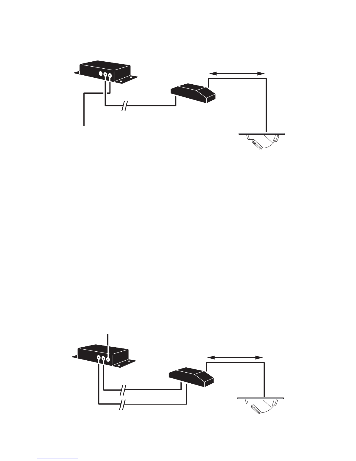
Remotely dimmable power-supply configuration
Note: This configuration does not apply for Alien 05 Eyeball models
as they draw their power via the transformer that is built into
the Halo Recessed fixture housing. These transformers are not
dimmable.
In this configuration, one or more dimmable transformers supply 12V power
to one or more Alien 05s, and are connected to the 0-10V analog output on
the 05 Driver. The transformer can be powered through the 10A mains relay
(if remote power on/off is required), or directly from the mains supply.
Mains
80-250V AC
50/60 Hz
Max
Driver
Dim. Trans.
45 cm
12V AC
10 Configuring an Alien 05 system
80-250V AC
50/60 Hz
Analog 0-10V
Page 11

Using the Oracle controller, or a DMX control device, it is possible to dim,
and power on and off the Alien 05s via the intensity channel.
Warning Do not draw more than 10 amps through the 05 Driver mains
relay. If the mains supply is under 200 volts and the number of
connected Alien 05’s is over 15, check that the combined
current draw of all transformers will not exceed 10 A.
Connecting transformers to a power supply
Supplying power through the 05 Driver to the transformers that power the
Alien 05 luminaires is optional and transformers may be connected directly
to the mains supply if there is no requirement for remote dimming or
power/on via the 05 Driver. Refer the documentation supplied with you
transformer for guidance.
In the cases that remote:
• Power on/off via the 05 Driver is required, transformers may be wired
through the 05 Driver’s mains output relay. The relay cuts power to the
transformer when the intensity is set to less than 10 percent. It supplies
power when the intensity is set to 10 percent or more.
• Dimming is required, a dimmable transformer may be connected through
the analog 0 - 10 V output on the 05 Driver. This output controls the dimmer
function only and does not provide power to illuminate the luminaires. This
function is not available for Alien 05 Eyeball models.
Connecting transformers to the 05 Driver
To connect transformers to the 05 Driver, perform the following steps:
1 If the mains supply is under 200 volts and the number of connected Alien
05’s is over 15, verify that the combined current draw of all transformers will
not exceed 10 A.
2 Verify that the 05 Driver is isolated from AC power.
3 If wiring more than 1 transformer, connect the transformer leads to a
suitable power distribution strip or junction with a single lead to the 05
Driver. If the transformers are dimmable, similarly gather the control leads to
a parallel junction.
4 Remove top cover of the 05 Driver. Feed transformer power lead through
opening in the front panel labelled “Mains Output Relay”. If required, feed
the dimmer control lead through the opening labelled “0 - 10V Dimmer Out”.
Connect as shown on top cover.
5 Replace the cover.
Configuring an Alien 05 system 11
Page 12
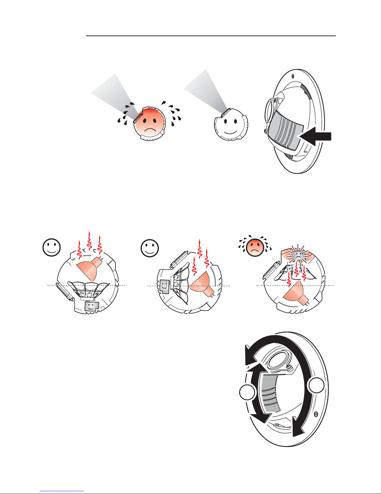
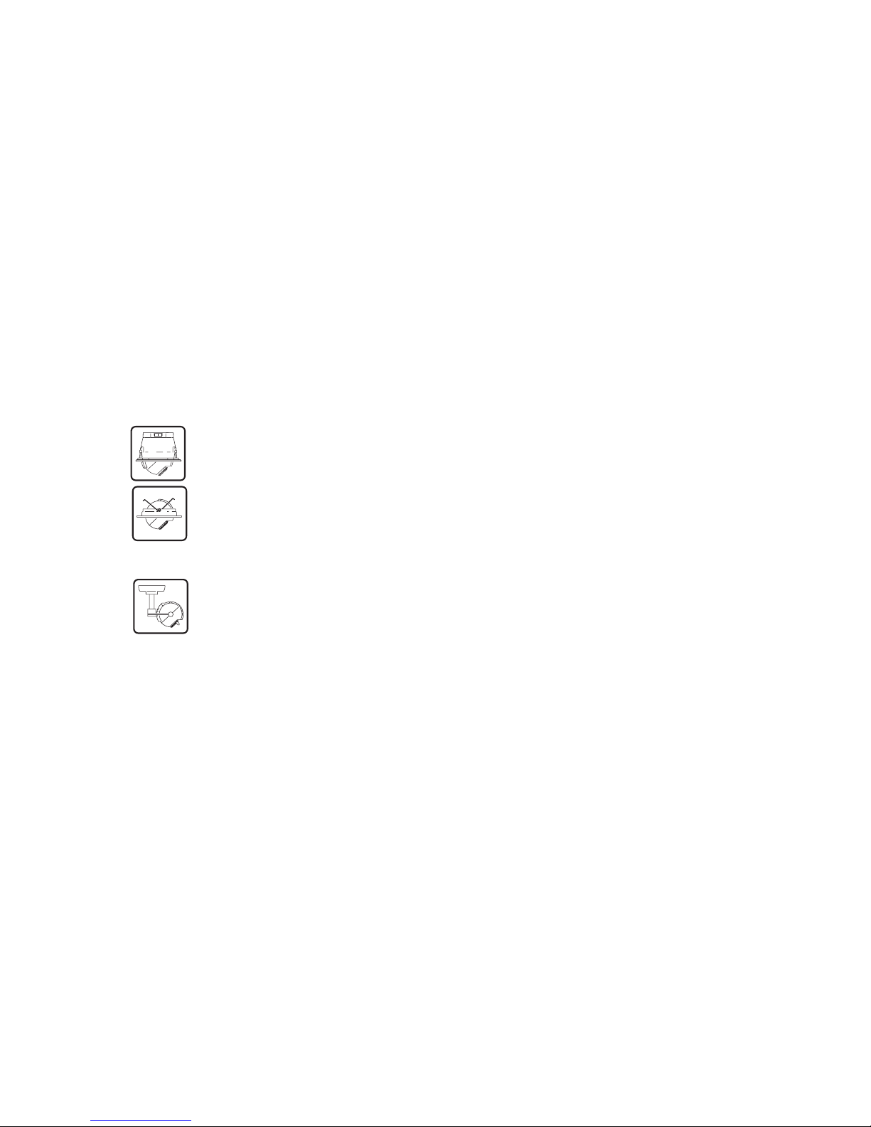
Orientation in up-light installations
Important! If installing the Alien 05 as an up-light, position the sphere so
that the motor vent is below the lens.
The motor vent is the vent closest to the lens
(see illustration on right).
The illustrations below show how to minimize heat stress on the color wheel
motor. Down-light installations (a) are straightforward. However, in up-light
installations (b and c), ensuring that the motor vent is below the lens, as in
(b), will optimize motor cooling.
abc
If an Alien 05 Recessed or Eyeball has
been installed as in (c) above, it can be
adjusted to optimize motor cooling by
rotating the sphere through 180° (A) and
tilting (B) to re-aim the beam.
12 Configuring an Alien 05 system
A
B
Page 13

Installing an Alien
05 Recessed
This section describes in general terms how to mount the fixture and
connect it to data and AC power. These procedures shall be performed by
qualified professionals.
We recommend that you perform the installation steps in the following order:
1 Install the 05 Driver and 05 Repeaters. See the 05 Driver user manual and
the 05 Repeater user manual.
2 Identify locations for the Alien 05s using the guidelines below.
3 Identify and acquire the pre-requisites described in “Prerequisites” on page
14.
4 Cut mounting holes (see page 15).
5 Lay the network cables between the 05 Driver/05 Repeaters and the Alien
3
05 mounting holes. See page 7.
6 Install the transformers close to the Alien 05 mounting holes and connect
them to the 05 Driver or power supply. See page 9.
7 Connect the Alien 05 to the network and transformer cables and install it in
the mounting hole. See page 15.
Fixture location
The Alien 05 Recessed can be used as either a ceiling fixture, or be
positioned in a wall as an up-light, down-light or sidelight.
Do not locate the Alien 05 recessed in an unventilated space. Install the
fixture in a location where it is:
• At least 0.5 meters (20 inches) away from the surface to be illuminated.
• Away from accidental public contact, as the surface of the sphere gets hot up to 90 ° C (194° F).
• Not more than 45 cm (17.7 inches) cable length away from the transformer.
Installing an Alien 05 Recessed 13
Page 14

• Not more than 40 cable metres away from the 05 Driver/05 Repeater.
Warning The Alien 05 Recessed is designed to be installed in a wall or
ceiling panel that is less than 20 mm (0.8 in) thick.
The standard Alien 05 can be modified for installation in a wall
or ceiling panel that is 20-30 mm (1.2 inches) in thickness. To
perform this modification order three Hexagon Socket Head Cab
Screws (M4x60) from your Martin dealer (P/N 08071205) and
change these with the three screws supplied with the product.
The product is not designed for installation in other
environments.
Ensure that Alien 05 Recessed models are installed with at least 50 mm (2
in) of clear space around the air vent at the rear of the fixture (total space
required including the depth of the fixture is 168 mm (6.6 in)).
Prerequisites
Before installing the Alien 05 Recessed:
• Ensure that you have a 12 V AC halogen lamp transformer (not supplied).
Each Alien 05 draws 50 watts of power at 4.2 amps from an electronic
transformer that supplies 12 volt AC at 50 or 60 hertz. If you are installing
multiple Alien 05s you can use one or more transformers, specified to the
number of Alien 05s power is being supplied to, but note that the cable
length between transformers and the Alien 05 luminaires that they supply
power to must not be more than 45 cm (17.7 inches).
• Ensure that you have a CAT5 network cable (category 5 UTP patch cable, 4
pairs, 24 AWG) that is not longer than 10 metres (33 feet), and that can be
run from the Alien 05 to the 05 Driver unit.
• If you are daisy-chaining another Alien 05 then you need an additional CAT5
network cable, that is not longer than 10 metres (33 feet), to connect this
luminaire to the next one.
14 Installing an Alien 05 Recessed
Page 15
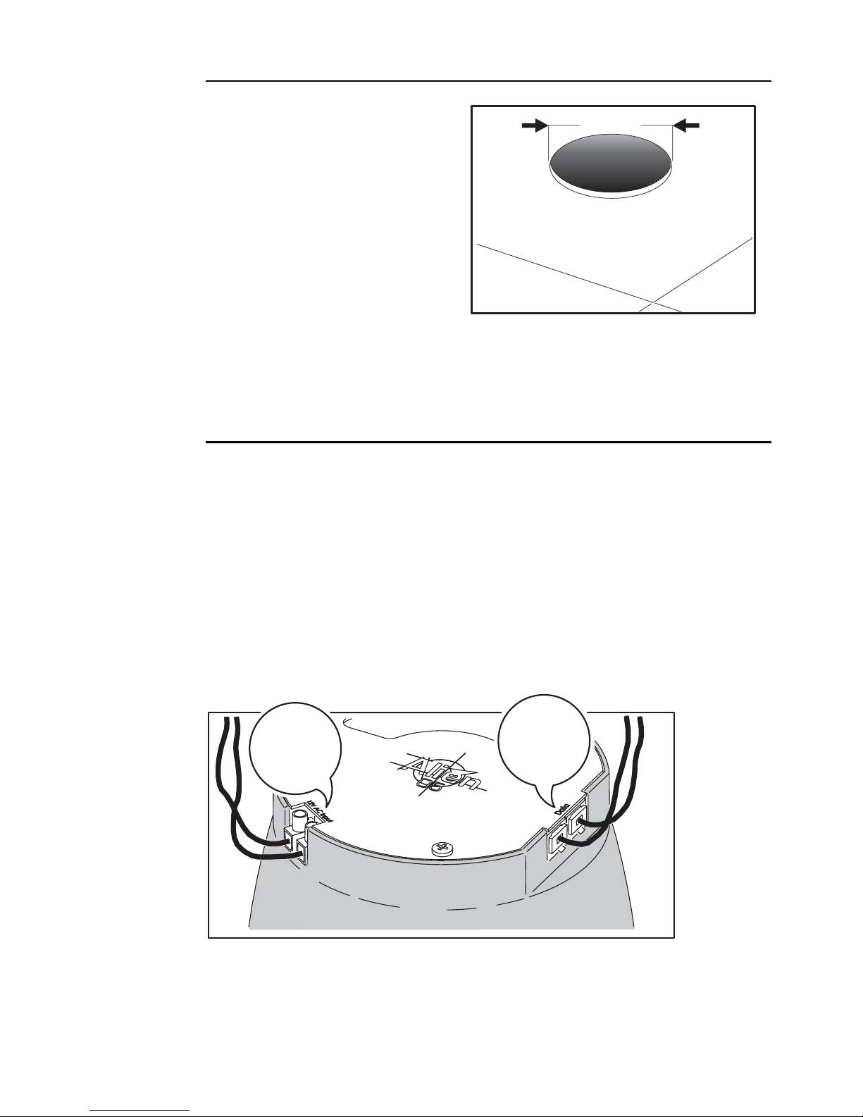
Mounting hole
Cut a round hole with a diameter
of 182 mm (7.2 in) in the panel in
which the Alien 05 is to be
installed. A cardboard ceiling
cutout template is supplied.
Note that it may be advisable to
perform this step for all the Alien
05s that are being installed, and
to then lay the power and
network cables between each
mounting hole, before inserting the luminaires. See the following sections.
182 mm
Connection and mounting
To install the Alien 05 Recessed:
1 Connect the power leads from the 12 V AC halogen lamp transformer.
Anchor these securely by tightening the screws. Note that the cable length
between the transformer and the Alien 05 must not be more than 45 cm
(17.7 inches).
2 Connect a CAT5 network cable that is directly or indirectly connected to the
05 Driver unit and, if the lamp is to be daisy-chained to a subsequent lamp,
connect a CAT5 network cable for the link to the next fixture. Note that it
does not matter which network socket is used.
Power
cables from
transformer
(12 V AC)
CAT5
network
cables
Installing an Alien 05 Recessed 15
Page 16
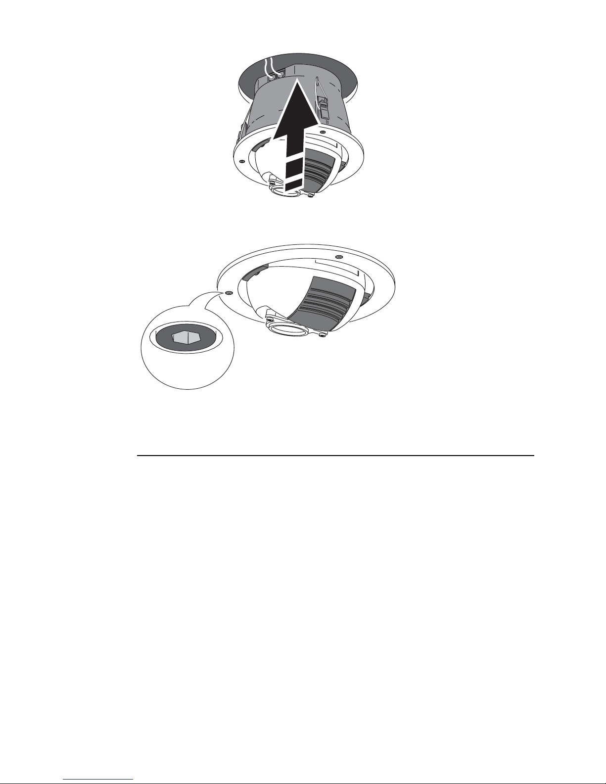
3 Once the cables are connected, insert the Alien 05 into the mounting hole.
4 Using a 3 mm Allen wrench, tighten the screws to lock the fixture in place.
Do not overtighten.
Removing the Alien 05 Recessed
Once installed it is not recommended that you remove an Alien 05
Recessed unless absolutely necessary.
To remove an Alien 05 Recessed:
1 Remove the 3 Allen screws in the mounting ring (shown in the previous
section) using a 3 mm Allen wrench.
2 Remove the fixture from the wall/ceiling panel.
During this process, particularly if the fixture is wall mounted, you might lose
one or more of the three clamp nuts (P/N 08074102) and rubber bands (P/N
34420503) that hold the fixture firmly in place when mounted. Should this
occur, replacement parts can be ordered from your Martin dealer.
16 Installing an Alien 05 Recessed
Page 17

Installing an Alien
05 Eyeball
This section describes in general terms how to mount the fixture and
connect it to data and AC power. These procedures shall be performed by
qualified professionals.
We recommend that you perform the installation steps in the following order:
1 Install the 05 Driver and 05 Repeaters. See the 05 Driver user manual and
the 05 Repeater user manual.
2 Identify locations for the your Alien 05 Eyeballs using the guidelines below.
3 Perform the pre-requisites described in “Prerequisites” on page 14.
4 Connect the recessed fixture housing to the network (see “Install the
network” on page 18).
5 Install the fixture using the procedure in “Connecting and mounting an Alien
4
05 Eyeball” on page 19
Fixture location
The Alien 05 Eyeball can be used as either a ceiling fixture, or be positioned
in a wall as an up-light, down-light or sidelight.
The Alien 05 Eyeball must be installed in a Cooper Lighting, Halo brand,
recessed low-volt non-IC fixture housing (item # H7LVT). For more
information refer to the Cooper Lighting web site
(http://www.cooperlighting.com/brands/halo/index.asp).
Do not locate the Alien 05 Eyeball in an unventilated space. Install the
fixture in a location where it is:
• At least 0.5 meters (20 inches) away from the surface to be illuminated.
• Away from accidental public contact, as the surface of the sphere gets hot up to 90 ° C (194° F).
• Not more than 40 cable metres away from the 05 Driver/05 Repeater.
Installing an Alien 05 Eyeball 17
Page 18

Prerequisites
Before installing the Alien 05 Eyeball:
• Install a Cooper Lighting, Halo brand, recessed low-volt non-IC fixture
housing (item # H7LVT). Connect the transformer on the fixture housing to
power. See the instructions supplied with the Halo fixture housing and
“Connecting transformers to a power supply” on page 11 of this user
manual.
• Ensure that you have a CAT5 network cable (category 5 UTP patch cable, 4
pairs, 24 AWG) that is not longer than 10 metres (33 feet), and that can be
run from the fixture housing to the 05 Driver unit.
• If you are daisy-chaining another Alien 05 then you need an additional CAT5
network cable, that is not longer than 10 metres (33 feet), to connect the
fixture housing to the next one.
Install the network
A network cable junction box and steel mounting strap are supplied with the
Alien 05 Eyeball. These are installed on the recessed low-volt fixture
housing in the following way:
1 Thread the steel strap through the slots on the junction box.
2 Wrap the steel strap around the recessed fixture housing and through its
buckle. Tighten the buckle locking screw.
18 Installing an Alien 05 Eyeball
Page 19

3 Pass the cable from the junction box through one of the holes in the
recessed fixture housing as shown in the illustration.
• Lay the network cables between the 05 Driver/05 Repeaters and the
junction box on the recessed fixture housing. See “Laying control network
cables” on page 8. Use CAT5 network cables and if the lamp is to be daisychained to a subsequent lamp, connect a CAT5 network cable for the link to
the next fixture. Note that it does not matter which network socket on the
junction box is used.
Connecting and mounting an Alien
05 Eyeball
1 Connect the data (D) connector on
the Alien 05 Eyeball to the
corresponding connector on the cable
from the network junction box. that is
attached to the recessed fixture
housing.
D
P
Installing an Alien 05 Eyeball 19
Page 20

2 Connect the power (P) connector on the Alien 05 Eyeball to the
corresponding connector on the recessed fixture housing (A).
A
3 Grasp both wire clips (B) simultaneously using both hands and insert the
Alien 05 Eyeball into the Halo recessed fixture housing (C and D).
B
4 Rotate and tilt the sphere to
the correct position and lock
C
D
it in place using a 2.5
millimeter Allen wrench.
5 Apply power.
20 Installing an Alien 05 Eyeball
Pan/tilt lock
Page 21

Installing an Alien
05 Stem Mount
This section describes in general terms how to mount the fixture and
connect it to data and AC power. These procedures shall be performed by
qualified professionals.
We recommend that you perform the installation steps in the following order:
1 Install the 05 Driver and 05 Repeaters. See the 05 Driver user manual and
the 05 Repeater user manual.
2 Identify locations for the Alien 05 Stem Mounts using the guidelines below.
3 Perform the pre-requisites described in “Prerequisites” on page 21.
4 Install the fixture using the procedure in “Connecting and mounting an Alien
05 Stem Mount” on page 22
5
Fixture location
Install the fixture in a location where it is:
• At least 0.5 meters (20 inches) away from the surface to be illuminated.
• Away from accidental public contact, as the surface of the sphere gets hot up to 90 ° C (194° F).
• Not more than 45 cm (17.7 inches) cable length away from the transformer.
• Not more than 40 cable metres away from the 05 Driver/05 Repeater.
Prerequisites
Before installing the Alien 05 Stem Mount:
• Ensure that you have all three components - an Alien 05 Stem Mount, 12V,
50 W, a 600 mm or a 150 mm Arm, and a Base that is appropriate to your
local mains supply (two models are available - each with a dimmable
transformer included - 90-130V/12V-75W, or 200-250V/12V-75W)
Installing an Alien 05 Stem Mount 21
Page 22

• Ensure that you have a CAT5 network cable (category 5 UTP patch cable,
4 pairs, 24 AWG) that is not longer than 10 metres (33 feet), and that can
be run from the Alien 05 to the 05 Driver unit.
• If you are daisy-chaining another Alien 05 then you need an additional
CAT5 network cable, that is not longer than 10 metres (33 feet), to
connect this luminaire to the next one.
• We recommend that you lay power and data cables out to the mounting
positions of the Alien 05 Stem Mounts. Refer to “Laying control network
cables” on page 8 and “Connecting transformers to a power supply” on
page 11.
Connecting and mounting an Alien
05 Stem Mount
To connect and mount an Alien 05 Stem Mount you need:
• A pair of retaining ring pliers
• 2.5 mm and 4 mm Allen wrenches
• An electric drill and bits appropriate to the mounting surface
• 3 units of 5 mm mounting hardware
• A small Phillips screwdriver
There are two possible configurations for mounting an Alien 05 Stem
mount - standard, or reversed. In the standard configuration the base
containing the transformer is affixed to the mounting surface - this can be
used for ceiling or wall mounting the fixture. In the reversed configuration
the base is positioned on the other side of a ceiling surface. This
Page 23

Base
Base cover
Cover ring
Bracket
Head
Arm
configuration is not intended for mounting on a vertical surface such as a
wall.
Snap ring
Arm cover
• “Installation using the standard configuration” on page 24, or
• “Installation using the reversed configuration” on page 27
Standard configuration Reversed configuration
Note that in either configuration that power and data cables can be
connected to the base either through the three holes in the side of the
Base cover or through the hole in the center of the base.
Before you start, ensure that the components are disassembled as shown
in the previous exploded views. Then perform the appropriate installation
procedure:
Page 24

Installation using the standard configuration
1 Fasten the base plate to the mounting surface using 5 mm mounting
hardware. We recommend that you use the two keyholes first and then
fasten the base plate into place using the third hole.
Ø5.5mm
Ø11.5mm
2 Lay the network cables between the 05 Driver/05 Repeaters and the data
terminal (A) on the Base. See “Laying control network cables” on page 8.
Use CAT5 network cables and if the lamp is to be daisy-chained to a
subsequent lamp, connect another CAT5 network cable for the link to the
next fixture. Note that it does not matter which network socket on the data
terminal is used.
A
A
B
C
3 Connect the transformer on the Base to power at the terminal (C). See
“Connecting transformers to a power supply” on page 11 of this user
manual. Anchor the power cable using the clamp (B).
24 Installing an Alien 05 Stem Mount
Page 25

4 Remove the snap ring from the end of the Arm using a pair of retaining ring
pliers. Slide the Arm through the hole on the bracket of the Alien 05 Stem
Mount head and replace the snap ring.
5 If you have attached a 600 mm long arm then attached the cable extension
that is supplied to the cable on the Alien 05 Stem Mount head.
6 Slide the base cover over the arm.
7 Thread the power and data cable up through the arm and screw the arm
cover into place using a small Phillips screwdriver.
Base cover
Arm cover
Installing an Alien 05 Stem Mount 25
Page 26

Remove pin (B) and insert the end of the arm (A) into the base. Re-insert
and screw the pin into place. The cables are threaded up through the center
of the base (as shown) and then through one of the slots in the base.
B
A
8 Connect the data cable (A) to the data terminal (A). Connect the power
connectors (B).
A
B
A
B
9 If the power and data cables are to pass out
through the side of the base cover then
remove the three rubber grommets that sit in
the cover holes, make a cut in each of them,
place them over their respective cables, and
push them back into place on the cover.
26 Installing an Alien 05 Stem Mount
Page 27

10 Push the base cover up into place and screw it into position using a 2.5 mm
Allen wrench.
11 Rotate the mounting bracket and tilt the sphere to the correct position and
lock them into position using a 2.5 millimeter Allen wrench.
12 Apply power.
Installation using the reversed configuration
In the reversed configuration the base is positioned on the other side of a
ceiling surface and is held in place by the addition of a cover ring (A). This
configuration is not intended for mounting on a vertical surface such as a
wall. The cover ring is held in place by two counter-sunk M4 x 16 mm
screws. These can be used through a ceiling surface that is up to 5 mm (1/5
inch) think. If the ceiling is thicker than this you will need to purchase two
longer counter-sunk M4 screws.
Installing an Alien 05 Stem Mount 27
Page 28

1 Cut or drill a 45 - 50 mm (1.8 - 2 inch) hole in the ceiling surface.
2 Remove the snap ring from the end of the Arm using a pair of retaining ring
pliers. Slide the Arm through the hole on the bracket of the Alien 05 Stem
Mount head and replace the snap ring.
3 If you have attached a 600 mm long arm then attached the cable extension
that is supplied to the cable on the Alien 05 Stem Mount head.
28 Installing an Alien 05 Stem Mount
Page 29

4 Thread the power and data cable up through the arm and screw the arm
cover into place using a small Phillips screwdriver.
5 Slide the cover ring over the arm.
6 Remove the pin the lies across the hole in the center of the base.
7 Insert the end of the arm thought the hole in the ceiling into the base. The
cables are threaded up through the center of the base and then down
through one of the slots.
8 Re-insert and screw the pin into place on the base, locking the arm into
position.
9 Screw the cover ring to the base using two M4 counter-sunk screws. (two 16
mm screws are provided). If the ceiling surface is thicker than 5 mm (1/5th
inch) then you will need to purchase some longer screws.
10 Connect the data cable (A) to the data terminal (A). Connect the power
connectors (B).
B
A
B
11 Lay the network cables between the 05 Driver/05 Repeaters and the data
terminal (A) on the base. See “Laying control network cables” on page 8.
Use CAT5 network cables and if the lamp is to be daisy-chained to a
subsequent lamp, connect another CAT5 network cable for the link to the
A
Installing an Alien 05 Stem Mount 29
Page 30

next fixture. Note that it does not matter which network socket on the data
terminal is used.
A
A
B
C
12 Connect the transformer on the base to power at the terminal (C). See
“Connecting transformers to a power supply” on page 11 of this user
manual. Anchor the power cable using the clamp (B).
13 If the power and data cables are to pass out
through the side of the base cover then
remove the three rubber grommets that sit in
the base cover holes, make a cut in each of
them, place them over their respective cables,
and then push the grommets back into place
on the base cover.
14 Place the base cover over the base and screw
it into position using a 2.5 mm Allen wrench.
15 Rotate the mounting bracket and tilt the sphere to the correct position and
lock them into position using a 2.5 millimeter Allen wrench.
16 Apply power.
30 Installing an Alien 05 Stem Mount
Page 31

General operation
The Alien 05 effects (color filter selection and the speed of color changes)
are controlled by an 05 Driver unit. Operators can develop programs, or
issue control commands to an 05 Driver using the Oracle dedicated control
unit, any DMX controller, DMX recorder, or any other USITT DMX512
compliant controlling device. For more information refer to the:
• 05 Driver user manual, P/N 35000107
• Oracle user manual, P/N 35000108
• The user documentation for the relevant DMX control device
In the absence of an Oracle or DMX controlling device, simple stand-alone
functions are available via DIP switches on the 05 Driver unit. See the
Martin 05 Driver user manual.
6
Prolonging lamp life
For optimum lamp life, turn off the power whenever illumination is not
required for extended periods of an hour or more.
Positioning the beam
Warning! The surface of the Alien 05 sphere gets hot during operation -
up to 90° C (194° F). Switch off power and allow the sphere to
cool for at least 5 minutes before touching.
The sphere can be rotated and tilted by hand to face any outwards direction.
Note that the Eyeball and Stem Mount models have pan/tilt locks.
General operation 31
Page 32

Positioning the Alien 05 Recessed beam
Do not tilt the sphere on an Alien 05
Recessed so that the light points into the
fixture as the build-up of heat may damage
the fixture. Forcing the sphere into this
position might also strain the cables within
the fixture.
If installing as an up-light, rotate the sphere
through 180° (A) and adjust the upward
angle (B) if necessary, so that the motor
vent is below the lamp as described in
“Orientation in up-light installations” on page
12.
B
Positioning the Alien 05 Stem Mount beam
Rotate the mounting bracket and tilt the sphere to the correct position and
lock them into position using a 2.5 millimeter Allen wrench.
A
Positioning the Alien 05 Eyeball beam
Alien 05 Eyeball models have a:
• Tilt stop to prevent over-rotation of the sphere
32 General operation
Page 33

• Pan/tilt lock that can be applied using a 2.5 millimeter Allen wrench.
Pan/tilt lock
If installing as an up-light, adjust the orientation of the sphere, if necessary,
so that the motor vent is below the lamp as described in “Orientation in uplight installations” on page 12.
Diffuser lens
The Alien 05 is supplied with a diffuser filter installed. This ensures a soft
illumination when illuminating close objects. When illuminating objects at
greater distances, it is recommended that you remove the diffuser filter. See
“Removing the diffuser filter” on page 38.
Color filters
The Alien 05 is supplied with eight color filters and an open position. The
filters sit in a motorized wheel that is controlled by the 05 Driver unit. The
positions and respective filters are as follows:
Position Filter
1 No filter - open position (a filter can be installed if required)
2 Color temperature correction (CTC) 5500-3400 K (warmer light)
3 Yellow 604
4 Red 305
5 Pink 312
6 CTC 3200-5600 K (colder light)
7 Blue 106
8 Blue 103
9 Green 201
General operation 33
Page 34

The numbers next to each color are OCLI (Optical Coating Laboratory, Inc.)
reference numbers.
Additional color filters can be ordered from your Martin dealer. A list of
available filters can be found in “Specifications” on page 44, or on the Martin
web site (http://www.martin.dk).
In the absence of an 05 Driver unit it is possible to open the fixture and
change the currently selected filter manually. Refer to “Replacing color
filters” on page 39 for information on how to access the color filter wheel.
Control
Refer to the 05 Driver user manual.
34 General operation
Page 35

Service
This section describes service procedures that can be performed by the
user:
• “Replacing the lamp”
• “Removing the diffuser filter” on page 38
• “Replacing color filters” on page 39
Refer all service not described here to a qualified Martin technician.
Warning! Disconnect the fixture from power before removing any cover.
7
Replacing the lamp
The Alien 05 uses the Osram ENL 50W 12V lamp (P/N 97000005). This
lamp has been designed specifically for the Alien 05. Installing any other
lamp is likely to result in a lower light output.
Warning! Disconnect power and allow the fixture sphere to cool for 15
minutes before starting this procedure.
The procedure for changing the lamp is slightly different for each of the
three Alien 05 models. See the appropriate section:
• “Alien 05 Recessed lamp replacement” on page 36, or
• “Alien 05 Eyeball lamp replacement” on page 36, or
• “Alien 05 Stem Mount lamp replacement” on page 38
Service 35
Page 36

Alien 05 Recessed lamp replacement
Lamp replacement requires a 3 mm Allen wrench. To replace the lamp:
1 Disconnect the fixture from power and allow it to cool.
2 Rotate the sphere to the position shown in the following illustration
3 Remove the lamp cover using a 3 mm Allen wrench.
4 Gently remove the old lamp from its housing and remove it from the socket.
5 Holding the new lamp by its glass base - insert it firmly and squarely into the
lamp socket.
6 Gently insert the lamp into its housing.
7 Replace the cover, being careful not to overtighten.
8 Rotate the sphere back to its normal operating position and reapply power.
Alien 05 Eyeball lamp replacement
To replace the lamp:
1 Disconnect the fixture from power and
allow it to cool.
2 Remove the Alien 05 from the Halo
recessed fixture housing.
3 Disconnect the data (D) and power (P)
connectors.
D
P
36 Service
Page 37

4 Slide the lamp out of its sprung
holder in the sphere.
5 Gently remove the old lamp from
the socket.
6 Holding the new lamp by its glass
base, insert it firmly and squarely
into the lamp socket.
7 Gently insert the lamp under the
sprung holder inside the sphere.
8 Reconnect the data (D) and power
(P) connectors (A).
9 Grasp the wire clips (B) and insert
the Alien 05 back into the Halo
recessed fixture housing (C).
A
B
10 Reapply power.
C
Service 37
Page 38

Alien 05 Stem Mount lamp replacement
Lamp replacement requires a 3 mm Allen wrench. To replace the lamp:
1 Disconnect the fixture from power and allow it to cool.
2 Remove the lamp cover using a 3 mm Allen wrench.
3 Gently remove the old lamp from its housing and remove it from the socket.
4 Holding the new lamp by its glass base - insert it firmly and squarely into the
lamp socket.
5 Gently insert the lamp into its housing.
6 Replace the cover, being careful not to overtighten.
7 Reapply power.
Removing the diffuser filter
The diffuser filter sits in a metal holder on the outside of the sphere in front
of the lens. It is held in place with a spring catch and is simple to remove
with the aid of a small screwdriver. The metal holder can be removed with a
2.5 mm Allen wrench.
Warning! The fixture sphere gets hot during operation. Disconnect power
and allow the fixture sphere to cool for 15 minutes before
removing the diffuser filter.
38 Service
Page 39

Replacing color filters
The positions on the color wheel are as follows:
1
2
3
4
5
The filters that are supplied as standard are:
Position Filter
1 No filter - open position (a filter can be installed if required)
2 Color temperature correction (CTC) 5500-3400 K (warmer light)
3 Yellow 604
4 Red 305
6
9
8
7
5 Pink 312
6 CTC 3200-5600 K (colder light)
7 Blue 106
8 Blue 103
9 Green 201
The procedure for changing the filters is slightly different for each of the
three Alien 05 models. See the appropriate section:
• “Alien 05 Recessed color filter replacement” on page 40, or
• “Alien 05 Eyeball color filter replacement” on page 40, or
• “Alien 05 Stem Mount color filter replacement” on page 42
Service 39
Page 40

Alien 05 Recessed color filter replacement
Color filter replacement requires a 3 mm Allen wrench.
Warning! Allow the fixture sphere to cool for 15 minutes before removing
the color filter cover.
To replace color filters:
1 Disconnect the fixture from power and
allow it to cool.
2 Rotate the sphere to the position shown
here.
3 Remove the color-filter access-cover
using a 3 mm Allen wrench. The filters
clip into holders on the wheel. Being
careful not to place finger prints on the
filters, rotate the wheel, and replace the
appropriate filters.
4 Replace the cover, being careful not to overtighten.
5 Rotate the sphere back to its normal operating position and reapply power.
Alien 05 Eyeball color filter replacement
Warning! Allow the fixture to cool for 15 minutes before removing.
To replace color filters:
1 Disconnect the fixture from power and allow it to cool.
2 Remove the Alien 05 from the Halo recessed fixture housing.
3 Disconnect the data (D) and power
(P) connectors.
4 The color filter wheel is accessible
from hole in the sphere at the rear of
the fixture.
D
P
40 Service
Page 41

5 The filters clip into holders on the wheel. Being careful not to place finger
prints on the filters, rotate the wheel, and replace the appropriate filters.
A
6 Reconnect the data (D) and power (P) connectors (A).
7 Grasp the wire clips (B) and insert the Alien 05 back into the Halo recessed
fixture housing (C).
B
8 Reapply power.
C
Service 41
Page 42

Alien 05 Stem Mount color filter replacement
Color filter replacement requires a 3 mm Allen wrench.
Warning! Allow the fixture sphere to cool for 15 minutes before removing
the color filter cover.
To replace color filters:
1 Disconnect the fixture from power and allow it to cool.
2 Remove the access-cover using a 3 mm Allen wrench.
3 The filters clip into holders on the wheel. Being careful not to place finger
prints on the filters, rotate the wheel, and replace the appropriate filters.
4 Replace the cover, being careful not to overtighten.
5 Rotate the sphere back to its normal operating position and reapply power.
42 Service
Page 43

Troubleshooting
Problem Probable cause(s) Remedy
8
No response from fixture when
power is applied.
Fixture does not respond
correctly to 05 Driver unit
No light, lamp cuts out
intermittently.
No power to fixture. Check power cables.
05 Driver unit not connected. Connect 05 Driver unit.
Bad data link connection. Inspect cables and correct
poor connections and/or
broken cables.
Lamp missing or blown. Turn the power off and replace
the lamp.
Fixture or lamp is too hot. Allow fixture to cool. If problem
persists, contact service
technician.
Cables to the transformer not
fastened securely or loose.
Table 1
Check power cables.
Troubleshooting 43
Page 44

S
PECIFICATIONS
A
44 Specifications
Page 45

Alien 05 Recessed Specifications
Physical
Diameter of fixture at widest point. . . . . . . . . . . . . . . . . . . . . . . . . . . . . . . .195 mm (7.7 in)
Depth of recessed base . . . . . . . . . . . . . . . . . . . . . . . . . . . . . . . . . . . . . . . . .118 mm (4.7 in)
Maximum protrusion of fixture from mounting surface. . . . . . . . . . . . . . . . .65 mm (2.6 in)
Weight. . . . . . . . . . . . . . . . . . . . . . . . . . . . . . . . . . . . . . . . . . . . . . . . . . . . . . .1.2 kg (2.6 lbs)
Source
Lamp . . . . . . . . . . . . . . . . . . . . . . . . . . . . . . . . . . . . . . . . MR16, 50 W, 12 V, glass reflector
Approved models . . . . . . . . . . . . . . . . . . . . . . . . . . Osram ENL 50W 12V custom reflector
Lamp base . . . . . . . . . . . . . . . . . . . . . . . . . . . . . . . . . . . . . . . . . . . . . . . . . . . .GX 5.32.2 lbs)
Dynamic effects
8 color filters plus open
Speed control
Lamp ON/OFF
Intensity (when using a dimmable transformer)
Control & Programming
Control options (via O5 Driver unit). . . . . . . . . . . . . . . . . . . . . . . . . . . . . . . . . . . DMX-512
Control options (via O5 Driver unit). . . . . . . . . . . . . . . . . . .stand-alone using DIP switches
Control options (via O5 Driver unit). . . . . . . . . . . . . . . . . dedicated operator panel - Oracle
Data input . . . . . . . . . . CAT5 network cable (not supplied) - maximum length 10 m (33 ft)
Data output . . . . . . . . . CAT5 network cable (not supplied) - maximum length 10 m (33 ft)
Installation
Minimum distance to illuminated objects. . . . . . . . . . . . . . . . . . . . . . . . . . . .0.5 m (16.7 in)
Minimum clearance around air vent . . . . . . . . . . . . . . . . . . . . . . . . . . . . . . . . . 50 mm (8 in)
Maximum cable distance to transformer. . . . . . . . . . . . . . . . . . . . . . . . . . . .45 cm (17.7 in.)
Indoor orientation . . . . . . . . . . . . . . . . . . . . . . . . Any (ceiling panel or wall recommended)
Maximum thickness of ceiling/wall panel . . . . . . . . . . . . . . . . . . . . . . . . . . .20 mm (0.8 in)
Diameter of mounting hole. . . . . . . . . . . . . . . . . . . . . . . . . . . . . . . . . . . . . .182 mm (7.2 in)
Design standards
EU safety. . . . . . . . . . . . . . . . . . . . . . . . . . . . . . . . . . . . . . . . . . . . . . . . . . . . . EN 60598-2-2
Thermal
Maximum ambient temperature (Ta) . . . . . . . . . . . . . . . . . . . . . . . . . . . . . . .40° C (104° F)
Maximum surface temperature, steady state, Ta=40° C. . . . . . . . . . . . . . . . 90 ° C (194° F)
Cooling . . . . . . . . . . . . . . . . . . . . . . . . . . . . . . . . . . . . . . . . . . . . Convection cooling system
AC Supply
Alien 05 power supply . . . . . . . . . . . . . .12 V AC halogen lamp transformer (not supplied)
05 Driver unit power supply . . . . . . . . . . . . . . . . . . . . . . . . . . . . . . . . . . . . . . . Auto-ranging
Page 46

Maximum power and current
Alien 05: 12 V 50/60 Hz. . . . . . . . . . . . . . . . . . . . . . . . . . . . . . . . . . . . . . . . . . . 50 W, 4.2 A
Construction
Housing. . . . . . . . . . . . . . . . . . . . . . . . Die cast aluminum and polyamide PA 6 (30% glass)
Color . . . . . . . . . . . . . . . . . . . . . . . . . . . . . . . . . . . . . . . . . . . . . . . . . . . .Aluminum and gray
Ordering information
Alien 05 Recessed, 12V, 50 W . . . . . . . . . . . . . . . . . . . . . . . . . . . . . . . . . . . . P/N 90340000
05 Driver . . . . . . . . . . . . . . . . . . . . . . . . . . . . . . . . . . . . . . . . . . . . . . . . . . . . . P/N 90722010
05 Repeater . . . . . . . . . . . . . . . . . . . . . . . . . . . . . . . . . . . . . . . . . . . . . . . . . . . P/N 90722020
Oracle controller . . . . . . . . . . . . . . . . . . . . . . . . . . . . . . . . . . . . . . . . . . . . . . . P/N 90722000
Included items
User manual
Osram ENL 50W 12V
CTC 5500-3400 color filter (position 2)
Yellow 604 color filter (position 3)
Red 305 color filter (position 4)
Pink 312 color filter (position 5)
CTC 3200-5600 color filter (position 6)
Blue 106 color filter (position 7)
Blue 103 color filter (position 8)
Green 201 color filter (position 9)
Diffuser filter (installed)
Accessories
Hexagon Socket Head Cab Screws (M4x60) . . . . . . . . . . . . . . . . . . . . . . . . . P/N 08071205
Dimmable transformer - 230 V @ 50/60 Hz/35-105 W @ 12 V . . . . . . . . . . P/N 91611054
CAT5 network cables - 2 m (6.5 ft) x 50 pieces: . . . . . . . . . . . . . . . . . . . . . . P/N 91611044
CAT5 network cables - 5 m (16.4 ft) x 30 pieces: . . . . . . . . . . . . . . . . . . . . . P/N 91611045
CAT5 network cables - 10 m (32.8 ft) x 15 pieces: . . . . . . . . . . . . . . . . . . . . P/N 91611046
Osram ENL 50W 12V: . . . . . . . . . . . . . . . . . . . . . . . . . . . . . . . . . . . . . . . . . . P/N 97000005
Fresnel lens (34 degrees field angle). . . . . . . . . . . . . . . . . . . . . . . . . . . . . . . . P/N 91610025
Blue 101 color filter . . . . . . . . . . . . . . . . . . . . . . . . . . . . . . . . . . . . . . . . . . . . P/N 62327058
Blue 104 color filter . . . . . . . . . . . . . . . . . . . . . . . . . . . . . . . . . . . . . . . . . . . . P/N 62327052
Blue 108 color filter . . . . . . . . . . . . . . . . . . . . . . . . . . . . . . . . . . . . . . . . . . . . P/N 62327055
Green 202 color filter . . . . . . . . . . . . . . . . . . . . . . . . . . . . . . . . . . . . . . . . . . . P/N 62327060
Green 206 color filter . . . . . . . . . . . . . . . . . . . . . . . . . . . . . . . . . . . . . . . . . . . P/N 62327054
Magenta 507 color filter . . . . . . . . . . . . . . . . . . . . . . . . . . . . . . . . . . . . . . . . . P/N 62327057
Orange 306 color filter . . . . . . . . . . . . . . . . . . . . . . . . . . . . . . . . . . . . . . . . . . P/N 62327059
Purple 502 color filter . . . . . . . . . . . . . . . . . . . . . . . . . . . . . . . . . . . . . . . . . . . P/N 62327061
Red 301 color filter . . . . . . . . . . . . . . . . . . . . . . . . . . . . . . . . . . . . . . . . . . . . . P/N 62327056
Yellow 603 color filter . . . . . . . . . . . . . . . . . . . . . . . . . . . . . . . . . . . . . . . . . . P/N 62327051
Page 47

Alien 05 Eyeball
Physical
Diameter of fixture at widest point. . . . . . . . . . . . . . . . . . . . . . . . . . . . . . . .195 mm (7.7 in)
Maximum protrusion of fixture from mounting surface. . . . . . . . . . . . . . . . .65 mm (2.6 in)
Weight. . . . . . . . . . . . . . . . . . . . . . . . . . . . . . . . . . . . . . . . . . . . . . . . . . . . . . . . 1 kg (2.2 lbs)
Source
Lamp . . . . . . . . . . . . . . . . . . . . . . . . . . . . . . . . . . . . . . . . MR16, 50 W, 12 V, glass reflector
Approved models . . . . . . . . . . . . . . . . . . . . . . . . . . Osram ENL 50W 12V custom reflector
Lamp base . . . . . . . . . . . . . . . . . . . . . . . . . . . . . . . . . . . . . . . . . . . . . . . . . . . .GX 5.32.2 lbs)
Dynamic effects
8 color filters plus open
Speed control
Lamp ON/OFF
Control & Programming
Control options (via O5 Driver unit). . . . . . . . . . . . . . . . . . . . . . . . . . . . . . . . . . . DMX-512
Control options (via O5 Driver unit). . . . . . . . . . . . . . . . . . .stand-alone using DIP switches
Control options (via O5 Driver unit). . . . . . . . . . . . . . . . . dedicated operator panel - Oracle
Data input . . . . . . . . . . CAT5 network cable (not supplied) - maximum length 10 m (33 ft)
Data output . . . . . . . . . CAT5 network cable (not supplied) - maximum length 10 m (33 ft)
Installation
Required housing . . . . . . . . . . . . . Cooper Lighting, Halo brand, recessed low-volt non-IC
Minimum distance to illuminated objects. . . . . . . . . . . . . . . . . . . . . . . . . . . .0.5 m (16.7 in)
Maximum cable distance to transformer. . . . . . . . . . . . . . . . . . . . . . . . . . . .45 cm (17.7 in.)
Indoor orientation . . . . . . . . . . . . . . . . . . . . . . . . Any (ceiling panel or wall recommended)
Design standards
EU safety. . . . . . . . . . . . . . . . . . . . . . . . . . . . . . . . . . . . . . . . . . . . . . . . . . . . . EN 60598-2-2
Thermal
Maximum ambient temperature (Ta) . . . . . . . . . . . . . . . . . . . . . . . . . . . . . . .40° C (104° F)
Maximum surface temperature, steady state, Ta=40° C. . . . . . . . . . . . . . . . 90 ° C (194° F)
Cooling . . . . . . . . . . . . . . . . . . . . . . . . . . . . . . . . . . . . . . . . . . . . Convection cooling system
AC Supply
Alien 05 power supply . . . . . . . . . . . . . . . . . . . . . . . . . 12 V AC halogen lamp transformer
(not supplied, but is part of the required fixture housing)
05 Driver unit power supply . . . . . . . . . . . . . . . . . . . . . . . . . . . . . . . . . . . . . . . Auto-ranging
Maximum power and current
Alien 05: 12 V 50/60 Hz. . . . . . . . . . . . . . . . . . . . . . . . . . . . . . . . . . . . . . . . . . . 50 W, 4.2 A
Page 48

Construction
Housing. . . . . . . . . . . . . . . . . . . . . . . . Die cast aluminum and polyamide PA 6 (30% glass)
Color . . . . . . . . . . . . . . . . . . . . . . . . . . . . . . . . . . . . . . . . . . . . . . . . . . . .Aluminum and gray
Ordering information
Alien 05 Eyeball, 12V, 50 W . . . . . . . . . . . . . . . . . . . . . . . . . . . . . . . . . . . . . P/N 90340100
05 Driver . . . . . . . . . . . . . . . . . . . . . . . . . . . . . . . . . . . . . . . . . . . . . . . . . . . . . P/N 90722010
05 Repeater . . . . . . . . . . . . . . . . . . . . . . . . . . . . . . . . . . . . . . . . . . . . . . . . . . . P/N 90722020
Oracle controller . . . . . . . . . . . . . . . . . . . . . . . . . . . . . . . . . . . . . . . . . . . . . . . P/N 90722000
Halo brand, recessed low-volt non-IC fixture housing. . . . . .Cooper Lighting item number
H7LVT
Included items
User manual
Osram ENL 50W 12V
CTC 5500-3400 color filter (position 2)
Yellow 604 color filter (position 3)
Red 305 color filter (position 4)
Pink 312 color filter (position 5)
CTC 3200-5600 color filter (position 6)
Blue 106 color filter (position 7)
Blue 103 color filter (position 8)
Green 201 color filter (position 9)
Diffuser filter (installed)
Steel strap and network junction box
Accessories
CAT5 network cables - 2 m (6.5 ft) x 50 pieces . . . . . . . . . . . . . . . . . . . . . . . P/N 91611044
CAT5 network cables - 5 m (16.4 ft) x 30 pieces . . . . . . . . . . . . . . . . . . . . . . P/N 91611045
CAT5 network cables - 10 m (32.8 ft) x 15 pieces . . . . . . . . . . . . . . . . . . . . . P/N 91611046
Osram ENL 50W 12V. . . . . . . . . . . . . . . . . . . . . . . . . . . . . . . . . . . . . . . . . . . P/N 97000005
Fresnel lens (34 degrees field angle). . . . . . . . . . . . . . . . . . . . . . . . . . . . . . . . P/N 91610025
Blue 101 color filter . . . . . . . . . . . . . . . . . . . . . . . . . . . . . . . . . . . . . . . . . . . . P/N 62327058
Blue 104 color filter . . . . . . . . . . . . . . . . . . . . . . . . . . . . . . . . . . . . . . . . . . . . P/N 62327052
Blue 108 color filter . . . . . . . . . . . . . . . . . . . . . . . . . . . . . . . . . . . . . . . . . . . . P/N 62327055
Green 202 color filter . . . . . . . . . . . . . . . . . . . . . . . . . . . . . . . . . . . . . . . . . . . P/N 62327060
Green 206 color filter . . . . . . . . . . . . . . . . . . . . . . . . . . . . . . . . . . . . . . . . . . . P/N 62327054
Magenta 507 color filter . . . . . . . . . . . . . . . . . . . . . . . . . . . . . . . . . . . . . . . . . P/N 62327057
Orange 306 color filter . . . . . . . . . . . . . . . . . . . . . . . . . . . . . . . . . . . . . . . . . . P/N 62327059
Purple 502 color filter . . . . . . . . . . . . . . . . . . . . . . . . . . . . . . . . . . . . . . . . . . . P/N 62327061
Red 301 color filter . . . . . . . . . . . . . . . . . . . . . . . . . . . . . . . . . . . . . . . . . . . . . P/N 62327056
Yellow 603 color filter . . . . . . . . . . . . . . . . . . . . . . . . . . . . . . . . . . . . . . . . . . P/N 62327051
Page 49

Alien 05 Stem Mount specifications
Physical
Pan radius . . . . . . . . . . . . . . . . . . . . . . . . . . . . . . . . . . . . . . . . . . . . . . . 170 mm (6.7 inches)
Protrusion from mounting surface (with 150 mm (6 inch) arm). . . . . . 215 mm (8.5 inches)
Protrusion from mounting surface (with 600 mm (24 inch) arm). . . . . .665 mm (26 inches)
Weight (with 150 mm (6 inch) arm) . . . . . . . . . . . . . . . . . . . . . . . . . . . . . . . . . . 1.3 (2.9 lbs)
Weight (with 600 mm (24 inch) arm) . . . . . . . . . . . . . . . . . . . . . . . . . . . . . . . . . 1.6 (3.5 lbs)
Source
Lamp: . . . . . . . . . . . . . . . . . . . . . . . . . . . . . . . . . . . . . . . MR16, 50 W, 12 V, glass reflector
Approved models:. . . . . . . . . . . . . . . . . . . . . . . . . . Osram ENL 50W 12V custom reflector
Base: . . . . . . . . . . . . . . . . . . . . . . . . . . . . . . . . . . . . . . . . . . . . . . . . . . . . . . . .GX 5.32.2 lbs)
Dynamic effects
8 color filters plus open
Speed control
Lamp on and off
Intensity
Control & Programming
Control options (via O5 Driver unit): . . . . . . . . . . . . . . . . . . . . . . . . . . . . . . . . . . DMX-512
Control options (via O5 Driver unit): . . . . . . . . . . . . . . . . . .stand-alone using DIP switches
Control options (via O5 Driver unit): . . . . . . . . . . . . . . . . dedicated operator panel - Oracle
Data input:. . . . . . . . . . CAT5 network cable (not supplied) - maximum length 10 m (33 ft)
Data output:. . . . . . . . . CAT5 network cable (not supplied) - maximum length 10 m (33 ft)
Installation
Minimum distance to illuminated objects. . . . . . . . . . . . . . . . . . . . . . . . . . . .0.5 m (16.7 in)
Maximum cable distance to transformer. . . . . . . . . . . . . . . . . . . . . . . . . . . .45 cm (17.7 in.)
Indoor orientation . . . . . . . . . . . . . . . . . . . . . . . . . . . . . . . . . .Ceiling mount recommended)
Design standards
EU safety. . . . . . . . . . . . . . . . . . . . . . . . . . . . . . . . . . . . . . . . . . . . . . . . . . . . . EN 60598-2-2
Thermal
Maximum ambient temperature (Ta) . . . . . . . . . . . . . . . . . . . . . . . . . . . . . . .40° C (104° F)
Maximum surface temperature, steady state, Ta=40° C. . . . . . . . . . . . . . . . 90 ° C (194° F)
Cooling . . . . . . . . . . . . . . . . . . . . . . . . . . . . . . . . . . . . . . . . . . . . Convection cooling system
Power supply - Base (230V/12V-75W)
12 V AC halogen lamp transformer . . . . . . . Lightech LET-75-12/230V R installed in base
Dimmable . . . . . . . . . . . . . . . . . . . . . . . . . . . . . . . . . . . . . . . . . . . . . . . . . . . . . . . . . . . . . Yes
Operating range. . . . . . . . . . . . . . . . . . . . . . . . . . . . . . . . . . . . . . . . . . . 200-250V/12V-75W
Conformity . . . . . . . . . . . . . . . . . . . . . . . . . . . . . . . . . . . VDE & VDE-EMV approved, CE
Maximum power and current . . . . . . . . . . . . . . . . . . . . .230 V @ 50/60 Hz = 75 W, 6.25 A
Power factor minimum . . . . . . . . . . . . . . . . . . . . . . . . . . . . . . . . . . . . . . . . . . . . . . . . . . 0.95
Page 50

Power supply - Base (120V/12V-75W)
12 V AC halogen lamp transformer . . . . . . . . . . . . . . . . .Lightech LET 75 installed in base
Dimmable . . . . . . . . . . . . . . . . . . . . . . . . . . . . . . . . . . . . . . . . . . . . . . . . . . . . . . . . . . . . . Yes
Operating range. . . . . . . . . . . . . . . . . . . . . . . . . . . . . . . . . . . . . . . . . . . . 90-130V/12V-75W
Conformity . . . . . . . . . . . . . . . . . . . . . . . . . . . . .UL & C-UL recognized, UL file # 164062
Maximum power and current . . . . . . . . . . . . . . . . . . . . . . . 120 V @ 60 Hz = 75 W, 6.35 A
Power factor minimum . . . . . . . . . . . . . . . . . . . . . . . . . . . . . . . . . . . . . . . . . . . . . . . . . . 0.95
Construction
Housing. . . . . . . . . . . . . . . . . . . . . . . . Die cast aluminum and polyamide PA 6 (30% glass)
Color . . . . . . . . . . . . . . . . . . . . . . . . . . . . . . . . . . . . . . . . . . . . . . . . . . . .Aluminum and gray
Ordering information
Alien 05 Stem Mount, 12V, 50 W. . . . . . . . . . . . . . . . . . . . . . . . . . . . . . . . . . P/N 90340200
600 mm Arm. . . . . . . . . . . . . . . . . . . . . . . . . . . . . . . . . . . . . . . . . . . . . . . . . . P/N 91611068
150 mm Arm. . . . . . . . . . . . . . . . . . . . . . . . . . . . . . . . . . . . . . . . . . . . . . . . . . P/N 91611067
Base (230V/12V-75W) . . . . . . . . . . . . . . . . . . . . . . . . . . . . . . . . . . . . . . . . . . P/N 90722030
Base (120V/12V-75W) . . . . . . . . . . . . . . . . . . . . . . . . . . . . . . . . . . . . . . . . . . P/N 90722040
05 Driver . . . . . . . . . . . . . . . . . . . . . . . . . . . . . . . . . . . . . . . . . . . . . . . . . . . . . P/N 90722010
05 Repeater . . . . . . . . . . . . . . . . . . . . . . . . . . . . . . . . . . . . . . . . . . . . . . . . . . . P/N 90722020
Oracle controller . . . . . . . . . . . . . . . . . . . . . . . . . . . . . . . . . . . . . . . . . . . . . . . P/N 90722000
Included items
User manual
Osram ENL 50W 12V
CTC 5500-3400 color filter (position 2)
Yellow 604 color filter (position 3)
Red 305 color filter (position 4)
Pink 312 color filter (position 5)
CTC 3200-5600 color filter (position 6)
Blue 106 color filter (position 7)
Blue 103 color filter (position 8)
Green 201 color filter (position 9)
Diffuser filter (installed)
Page 51

Accessories
CAT5 network cables - 2 m (6.5 ft) x 50 pieces . . . . . . . . . . . . . . . . . . . . . . . P/N 91611044
CAT5 network cables - 5 m (16.4 ft) x 30 pieces . . . . . . . . . . . . . . . . . . . . . . P/N 91611045
CAT5 network cables - 10 m (32.8 ft) x 15 pieces . . . . . . . . . . . . . . . . . . . . . P/N 91611046
Osram ENL 50W 12V. . . . . . . . . . . . . . . . . . . . . . . . . . . . . . . . . . . . . . . . . . . P/N 97000005
Fresnel lens (34 degrees field angle). . . . . . . . . . . . . . . . . . . . . . . . . . . . . . . . P/N 91610025
Blue 101 color filter . . . . . . . . . . . . . . . . . . . . . . . . . . . . . . . . . . . . . . . . . . . . P/N 62327058
Blue 104 color filter . . . . . . . . . . . . . . . . . . . . . . . . . . . . . . . . . . . . . . . . . . . . P/N 62327052
Blue 108 color filter . . . . . . . . . . . . . . . . . . . . . . . . . . . . . . . . . . . . . . . . . . . . P/N 62327055
Green 202 color filter . . . . . . . . . . . . . . . . . . . . . . . . . . . . . . . . . . . . . . . . . . . P/N 62327060
Green 206 color filter . . . . . . . . . . . . . . . . . . . . . . . . . . . . . . . . . . . . . . . . . . . P/N 62327054
Magenta 507 color filter . . . . . . . . . . . . . . . . . . . . . . . . . . . . . . . . . . . . . . . . . P/N 62327057
Orange 306 color filter . . . . . . . . . . . . . . . . . . . . . . . . . . . . . . . . . . . . . . . . . . P/N 62327059
Purple 502 color filter . . . . . . . . . . . . . . . . . . . . . . . . . . . . . . . . . . . . . . . . . . . P/N 62327061
Red 301 color filter . . . . . . . . . . . . . . . . . . . . . . . . . . . . . . . . . . . . . . . . . . . . . P/N 62327056
Yellow 603 color filter . . . . . . . . . . . . . . . . . . . . . . . . . . . . . . . . . . . . . . . . . . P/N 62327051
Page 52

www.martin-architectural.com • Olof Palmes Allé 18 • 8200 Aarhus N • Denmark
Tel: +45 8740 0000 •
Fax +45 8740 0010
 Loading...