

Page 1

MARTI
ELECTRONICS
RPU TRANSMITTER
MODELS: SRPT-30
SRPT-40A
Page 2

8/7/2003
RF EXPOSURE WARNING
This remote pickup unit (RPU) contains a radio frequency (RF) transmitter. During normal operation it sends
out radio frequency (RF) signals. In August 1996, the Federal Communications Commission (FCC) adopted
RF exposure guidelines with safety levels for wireless devices.
CAUTION: To maintain compliance with the FCC’s RF exposure guidelines, the antenna(s) used for this
transmitter must be installed to provide a separation distance of at least 6 meters from all persons during normal
operation and must not be co-located or operating in conjunction with any other antenna or transmitter. In
addition, no antenna with a gain of greater than 11 dBi shall be used.
Unauthorized antennas, modifications, or attachments could damage the transmitter and may violate FCC
regulations.
i
Page 3

8/7/2003
WARNING
THIS EQUIPMENT MUST BE OPERATED WITH A 3-PRONG
GROUNDED OUTLET RECEPTACLE. FAILURE TO USE A
PROPERLY GROUNDED OUTLET MAY RESULT IN IMPROPER
OPERATION OR SAFETY HAZARD!
LIMITED WARRANTY
The Seller warrants that, at the time of shipment, the products manufactured by the Seller are free from defects in
material and workmanship. The Seller's obligation under this warranty is limited to replacement or repair of such
products which are returned to Marti at its factory, transportation prepaid and properly insured, provided:
a. Notice of the claimed defect is given to Marti within one (1) year [two (2) years for STL systems] from date of
original shipment and goods are returned in accordance with Marti instructions.
b. Equipment, accessories, tubes and batteries not manufactured by Marti are subject to only such adjustments as
Marti may obtain from the supplier thereof.
c. This warranty does not apply to equipment which has been altered, improperly handled, or damaged in any way.
The Seller is in no event liable for consequential damages, installation cost or other costs of any nature as a result of the
use of the products manufactured or supplied by the Seller, whether used in accordance with instructions or not.
This warranty is in lieu of all others, either expressed or implied. No representative is authorized to assume for the Seller
any other liability in connection with Seller's products.
MAILING & SHIPPING ADDRESS:
Broadcast Electronics
MARTI Electronics Division
4100 North 24
th
Street
Quincy, IL 62301
The United States of America
COPYRIGHT NOTICE
©2001 All Rights Reserved
Marti Electronics
3rd printing, January 2003
No part of this manual may be reproduced, transmitted, transcribed, stored in a retrieval system , or translated into any
language, natural or computer, in any form or by any means, without the prior written permission of Marti Electronics.
ii
Page 4

8/7/2003
Artwork depicting circuitry in this manual is protected by copyright laws.
Information in this manual is subject to change without notice and does not represent a commitment on the part of Marti
Electronics.
Marti Electronics may make improvements and/or changes in this manual or in the product described herein at any time.
This product could include technical inaccuracies or typographical errors.
PHONE NUMBERS:
Sales (817) 735-8134
Service (217) 224-9600
FAX (817) 735-9340
iii
Page 5

8/7/2003
ABOUT THIS MANUAL
This manual supports both the SRPT-30 and SRPT-40A RPU transmitters for all standard (and some nonstandard) frequency bands. The SRPT-30/40A in some frequency bands may not yet be available during the
printing of this manual. The manual will be revised as new frequency bands become available.
Manual Part Numbers:
Kit, Binder and Manual: 979-9967-1
Manual Only: 566-035-1
iv
Page 6

TABLE OF CONTENTS
Introduction ..........………................................................................................................. 1
Specifications & Ordering................................................................................................. 4
Unpacking and Inspection ................................................................................................. 7
Installation ......................................................................................................................... 8
Antennas ........................................................................................................................... 16
Control, LED, & Connector Functions ……………………………………….………… 18
Operation ........................................................................................................................... 23
Theory of Operation .......................................................................................................... 31
Drawing 702-124 “SRPT-30/40A Functional Block Diagram”................................... 34
Drawing 702-117 “SRPT-30/40A RF Systems & Control”......................................... 35
8/7/2003
Recommended Test Equipment ………………………………………………………… 36
Tools For Alignment ……………………………………………………………………. 36
SRPT-30/40A Transmitter Factory Test Report …………………………………...…… 37
Calibration and Adjustments …………………................................................................. 38
Drawing 702-122 “SRPT-30/40A Adjustment Locations”……………………..…… 50
SRPT-30/40A Bill of Material and Schematics ……………............................................ 51
v
Page 7
8/7/2003
INTRODUCTION
See the SPECIFICATIONS & ORDERING section for a listing of available frequency
ranges and power models.
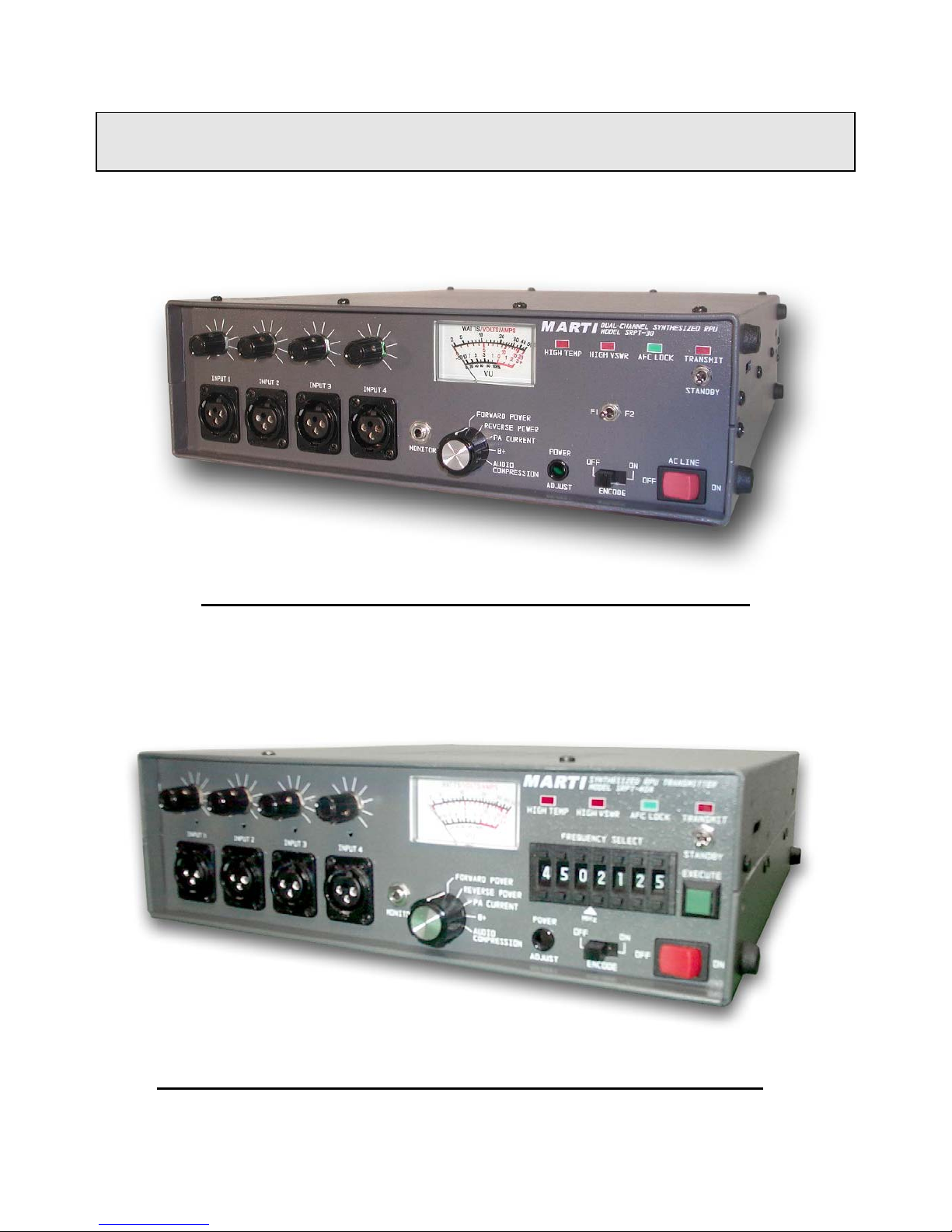
SRPT-30 DUAL-CHANNEL RPU TRANSMITTER
SRPT-40A FREQUENCY AGILE RPU TRANSMITTER
1
Page 8

8/7/2003
The Marti Models SRPT-30/40A are wide-band – high power RPU Transmitters designed to operate in the Remote
Pick-Up Broadcast Service as defined in Part 74, Subpart D, of the FCC Rules and Regulations. The SRPT-30 replaces
the Marti RPT-30 series of RPU’s. Like its predecessor, the SRPT-30 has two frequency channels and a four-input
mixer for mic/line audio. Unlike the RPT-30, the SRPT-30 uses synthesizer technology (not to be confused with
frequency agile) instead of the discrete crystal technology. Also the SRPT-30 is equipped with a wide-band power
amplifier that has a power output up to 30 watts that can be adjusted from the front panel. This, combined with the wideband synthesizer, benefits the operator in the following ways: (1) Frequency separation between F1 and F2 frequency
can be up to 50 MHz and (2) No RF tuning required.
The SRPT-40A also uses synthesizer technology with a wide-band power amplifier and requires no tuning. It is
frequency agile up to 50 MHz with a front-panel adjustable output power up to 60 watts in some models. The frequency
can be “dialed in” from the front panel and will automatically tune precisely to all frequencies divisible by 5 KHz or
6.25 KHz increments. It will also tune to within ±.00015% tolerance of most other frequencies not divisible by 5 KHz or
6.25 KHz increments. Finally, the user may operate the SRPT-40A in channel mode where he may store and recall up to
10 frequencies.
Refer to the SPECIFICATIONS & ORDERING section for a listing of available frequency ranges and power
models. These transmitters, when used with their recommended companion receiver, provide a remote broadcast link
having audio quality not approached by conventional voice communication radio equipment. The SRPT-30/40A
transmitters operate from 110-120 VAC or 220-240 VAC (manually switched internally), 50/60 Hz. The transmitters
can also operate on 12-15 VDC or 15-30 VDC battery (or external supply) in fixed, portable, or mobile, service. Four
audio input channels are provided with individual mixing gain controls. A meter and selector switch are provided for
monitoring forward and reverse power, power supply voltage, PA current and audio compression.
SRPT-30/40A Features:
· Four balanced microphone mixing inputs, one switchable to balanced line level
· No RF tuning required
· Switching Power Supply operates on any AC voltage from 110-120 VAC or 220-240 VAC
(manually switched internally), 50/60 Hz
· LEDs indicate High VSWR, Over-Temperature, AFC Lock, and Transmit
· Illuminated VU Meter for displaying Forward/Reverse Power, PA current, Power Supply
voltage, and Audio Compression
· Output power adjustable from front panel
· External 12-15 VDC or 15-30 VDC supply capability and external transmit control
· When operating on external 12-15 VDC supply, RPU will still remained locked for
external supply voltages as low as 7 VDC (Max power will de-rate linearly below 12 VDC)
· Fully suppresses external voltage supply noise such as car alternator
· High speed imbedded µ-controller to perform the following additional features:
· Power held constant over frequency, temperature, and voltage change
· High PA temp and VSWR warning indicators
· Auto frequency re-lock due to power outage
· Auto fold-back and recover due to high VSWR
· Auto shutdown due to very high PA temp – auto recover after cool down
· Auto shutdown due to open/short-output – auto recover
· Can operate as TSL (Models SRPT30-450T and SRPT40A-450T)
2
Page 9

8/7/2003
SRPT-40A Only Features:
· Continuous-duty output - 60 watts maximum in some models
· Frequency agile pushwheel switches allow selection of almost any frequency (100 Hz
steps) in operating band up to 50 MHz
· 10 user programmable channels
· No frequency look-up table required
· Remembers and locks-on last frequency during power-up
· Frequency resolution: 5 or 6.25 KHz steps – ± .00004% accuracy
- Most other frequencies (100 Hz steps) - ± .00015% accuracy
SRPT-30 Only Features:
· Continuous-duty output - 30 watts maximum most models
· Two frequency channels, F1 and F2, selected at time of order
· Up to 50 MHz separation between frequency channels
· Selected frequencies divisible by 5 or 6.25 KHz steps have a ± .00004% accuracy
- Most other selected frequencies have a ± .00015% accuracy
3
Page 10
Models SRPT-30 and SRPT-40A
Remote Pick-Up Broadcast Transmitters
SPECIFICATIONS & ORDERING
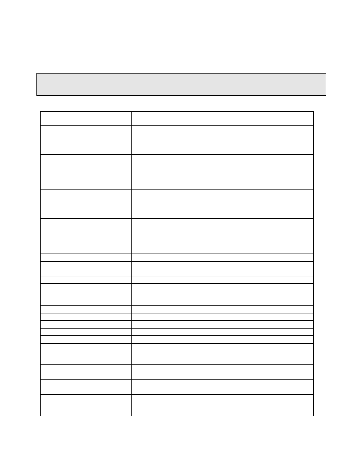
Conditions (unless specified otherwise): 1.5 VSWR, 110 VAC input with B+ = 13 Volts, 25ºC ambient
Frequency Bands and
Maximum Output Power:
Frequency Agility and
Accuracy
SRPT-40A (450 models and
less)
Frequency Agility and
Accuracy
SRPT-40A (800 models and
greater)
Frequency Selection and
Accuracy
SRPT-30 (450 models and less)
Frequency Selection and
Accuracy
SRPT-30 (800 models and
greater)
Operating Temp. Range:
Frequency Stability (over
operating temperature range):
Deviation:
Audio Bandwidth:
Signal-to-Noise:
Frequency Response:
Distortion:
Spurious Emissions:
RF Connector:
RF Output Impedance:
Audio Inputs:
Audio Input Levels:
Modulation Control:
Encoding:
Metering/Indicators:
See ORDERING INFORMATION below.
An executed “dialed-in” frequency that operates within model frequency
range will have an accuracy within:
(1) ± .00004% for frequency divisible by 5 or 6.25 KHz, or
(2) ± .00015% for MOST frequencies NOT divisible by 5 or 6.25 KHz*
An executed “dialed-in” frequency that operates within model frequency
range will have an accuracy within:
(1) ± .00004% for frequency divisible by 10 or 12.5 KHz, or
(2) ± .00015% for MOST frequencies NOT divisible by 10 or
12.5 KHz*
Two frequencies only, F1 and F2, determined at time of order, must
operate within model frequency range and will have an accuracy within:
(1) ± .00004% for frequency divisible by 5 or 6.25 KHz, or
(2) ± .00015% for MOST frequencies NOT divisible by 5 or 6.25 KHz*
Two frequencies only, F1 and F2, determined at time of order, must
operate within model frequency range and will have an accuracy within:
(1) ± .00004% for frequency divisible by 10 or 12.5 KHz, or
(2) ± .00015% for MOST frequencies NOT divisible by 10 or
12.5 KHz*
-10ºC to +45ºC
0.0001%
Adjustable, ± 20 KHz max
Standard: 7.5 KHz
Available: 5 KHz, 10 KHz, specials upon request
≥ 53 dB, 5 KHz deviation, 75 µsec pre/de-emphasis
± 1.5 dB from 50 Hz to Audio Bandwidth, 75 µsec pre/de-emphasis
≤ 2% from 50 Hz to Audio Bandwidth, 75 µsec pre/de-emphasis
More than 60 dB below carrier
Type N-Female
50 Ohms
Four balanced microphone (150 ohms) inputs (XLR-3) with mixing
controls. One input switchable to balanced line level at microphone #4
input and D connector on rear panel.
Microphone: -68 to -35 dBm
Line: 0 to +10 dBm, 6-800 Ohms
Broadcast-quality compressor/limiter built in.
Sub audible 27 Hz. tone encoder built in.
Illuminated meter indicates forward and reverse power, PA current, B+,
and audio compression. LEDs indicate TRANSMIT, AFC LOCK,
HIGH VSWR, and HIGH TEMP.
8/7/2003
4
Page 11

8/7/2003
Controls:
(4) Input level controls, METER control knob, ENCODE switch,
POWER ADJUST pot, TRANSMIT switch, and MONITOR jack.
SRPT-40A: FREQUENCY SELECT switches and EXECUTE switch
SRPT-30: F1/F2 switch
Power Requirements:
110-120 VAC or 220-240 VAC (manually switched internally on power
supply for proper input), 50/60 Hz
External DC operation on 12 - 15 volts or 15 - 30 volts.
Approximate PA Current
Rating (at maximum power
output):
Accessory Connector:
SRPT-40A: 8.5 to 10.5 Amps
SRPT-30: 6.5 to 7.5 Amps
(The data above varies across frequency band and from model to model)
15-pin D connector for DC power, remote control, encode, line level
input.
Weight:
Net: 8.25 Lbs (3.74 Kg).
Packed: 16.75 Lbs (7.60 Kg).
Dimensions:
11.5in (29.21cm) W x 3.5in (8.89cm) H x 14.3in (36.83cm) D.
Packed: 19in (48.26cm) W x 22in (55.88cm) H x 9in (22.86cm) D.
* - There does exist a few non-standard frequencies that will not automatically tune to within .00015% of
requested frequency. For those frequencies, the operator must change to the nearest standard frequency and
then manually tune the reference oscillator to desired frequency. Consult factory for frequencies not perfectly
divisible by 5 KHz or 6.25 KHz. We will be able to tell you how close the output will come to desired frequency.
5
Page 12

ORDERING INFORMATION
Conditions (unless specified otherwise): 1.5 VSWR, 110 VAC input with B+ = 13 Volts, 25ºC ambient
MARTI
PART #
SRPT30-150 135-185 30 20W 135-140 MHz
SRPT30-230 215-250 30 30W 215-250 MHz
SRPT30-250 235-265 30 25W 235-245 MHz
SRPT30-330 300-350 30 20W 300-315 MHz
SRPT30-450
-orSRPT30-450T
(for TSL RPU)
SRPT30-950 935-965 20 20W 935-960 MHz
SRPT40A-150 135-185 60 50W 135-140 MHz
SRPT40A-230 215-250 30 30W 215-250 MHz
SRPT40A-250 235-265 30 25W 235-245 MHz
SRPT40A-330 300-350 30 20W 300-315 MHz
SRPT40A-450
-orSRPT40A-450T
(for TSL RPU)
SRPT40A-950 935-965 20 20W 935-960 MHz
Frequency
Range
(MHz)
430-480 30 30W 430-480 MHz FCC ID: DDE-RPU-50W-450S
430-480 50 50W 430-465 MHz
Maximum
RF Output
Power (W)
Typical MAX RF
Output Power over
Frequency
30W 140-180 MHz
20W 180-185 MHz
30W 245-265 MHz
30W 315-350 MHz
18W 960-965 MHz
60W 140-175 MHz
50W 175-180 MHz
40W 180-185 MHz
30W 245-265 MHz
30W 315-350 MHz
45W 465-480 MHz
18W 960-965 MHz
FCC ID: DDE-RPU-60W-150S
(FCC Part 74 Subpart D)
(FCC Part 74 Subpart D)
10K0F3E, 25K0F3E, 50K0F3E
FCC ID: DDE-RPU-60W-150S
(FCC Part 74 Subpart D)
FCC ID: DDE-RPU-50W-450S
(FCC Part 74 Subpart D)
10K0F3E, 25K0F3E, 50K0F3E
8/7/2003
Certifications
Emission Designators:
25K0F3E, 30K0F3E
Emission Designators:
Emission Designators:
25K0F3E, 30K0F3E
Emission Designators:
Available OPTIONS for the SRPT-30/40A Transmitters
Marti No. Description
585-141 12-15 VDC External Supply Cable
585-142 15-30 VDC External Supply Cable
585-139 12-15 VDC Mobile Repeat Cable, CR/AR-10 to SRPT-30/40A
585-140 15-30 VDC Mobile Repeat Cable, CR/AR-10 to SRPT-30/40A
585-143 Fixed Repeat Cable, CR/AR-10 to SRPT-30/40A
700-250-13 Rack mounting kit
700-252-2 Mobile mounting kit
565-006-1 Racom 1402 Automatic Morse Code Station Identifier with mounting kit
585-088 SRPT30/40A TSL to Racom Cable Assembly
6
Page 13

8/7/2003
UNPACKING & INSPECTING
This equipment was factory tested, inspected, packed, and delivered to the carrier with utmost
care. Do not accept shipment from carrier which shows damage or shortage until the carrier's agent
endorses a statement of the irregularity on the face of the carrier's receipt. Without documentary
evidence, a claim cannot be filed.
Unpack equipment immediately upon receipt and thoroughly inspect for concealed damage. If
damage is discovered, stop further unpacking and request immediate inspection by local agent of
carrier. A written report of the agent's findings, with his signature is necessary to support claim.
Check your shipment against the shipping papers for possible shortage. Do not discard any packing
material until all items are accounted for. Small items are often thrown away with packing material.
Packing material should be retained until equipment testing is completed. Any equipment returned to
the factory should be packed in original cartons, insured, and pre-paid.
7
Page 14
8/7/2003
INSTALLATION
Install rack-mounted equipment in a well-ventilated, well-grounded, and shielded rack cabinet.
Do not locate solid-state equipment in a rack above tube-type equipment, which produces high
temperatures. It is highly recommended that if the equipment is mounted in a rack cabinet, a blower
should be installed in the cabinet as well.
Problems can also be avoided by locating this unit away from other equipment which has
transformers that produce strong magnetic fields. These fields can induce hum and noise into the
Marti equipment thus reducing performance. Strong radio-frequency (RF) fields should be avoided
where possible. Extensive shielding and filtering have been incorporated into this equipment to permit
operation in moderate RF environments. All equipment racks, cabinets, etc., should be bonded
together by wide copper grounding strap to ensure that all system elements are at RF ground potential.
Stationary Remote Broadcast Installation
The basic stationary remote installation consists of the SRPT-30/40A transmitter, a 110-120 or 220-240 VAC
power source, microphones and other audio program sources, and a portable antenna. Remotes using portable antennas
inside buildings have very limited range (typically less than one mile). If greater range is needed, consider locating the
transmitting antenna outside the building at a height necessary to provide a line-of-sight path to the receiving antenna.
This may not be practical if a great length of coaxial cable is required. Many broadcasters are using the Marti mobile
relay system to do remotes from inside buildings. This system consists of the originating transmitter with its antenna
inside the building which transmits to a “mobile relay” parked outside the building. The mobile relay consists of a Marti
Model AR-10 receiver and Marti RPT series transmitter with mobile antennas installed in a vehicle. The AR-10
receiver picks up the encoded signal originating from the RPT series transmitter located inside the building,
automatically turns on the relay transmitter (on a different frequency), which re-transmits the program to the distant
receiving antenna at the radio station studio or transmitter site. (Mobile relay equipment packages are available from
Marti.)
Stationary Remote Installation Procedure
1. The transmitter is normally located near the announcer or engineer to permit access to gain controls, microphone
inputs, the monitor jack, and metering.
Personnel must not be near the antenna when radiating. Locate antenna as far as possible from
people and equipment susceptible to RF radiation. Do not mount antenna directly on transmitter.
Refer to ANSI C95.1 “Limits on Non-Ionizing Radiation.”
8
Page 15

8/7/2003
2. With the SRPT-30/40A TRANSMIT/STANDBY switch in “STANDBY” position, plug the transmitter into a
grounded, three-prong, 110-120 or 220-240 VAC outlet.
WARNING
THE MANUAL SWITCH ON THE INTERNAL SWITCHING POWER SUPPLY IS SET AT THE
FACTORY TO THE 115 POSITION IF THE ORDER WAS FOR 110-120 VAC.
THE MANUAL SWITCH ON THE INTERNAL SWITCHING POWER SUPPLY IS SET AT THE
FACTORY TO THE 230 POSITION IF THE ORDER WAS FOR 220-240 VAC.
IF THE OPERATOR PLANS TO OPERATE THIS UNIT AT AN AC VOLTAGE DIFFERENT THAN
WHAT IS STATED ON ORDER, IT IS THE REPONSIBILITY OF THE PURCHASER TO SWITCH TO
THE APPROPRIATE POWER SUPPLY POSITION.
WARNING
DO NOT PLUG INTO AC WITHOUT FIRST KNOWING THE POSITION OF THE AC INPUT SWITCH
LOCATED ON THE SIDE OF THE INTERNAL POWER SUPPLY.
SEE AC LINE INPUT SELECTION – 110-120 VAC OR 220-240 VAC SUB-SECTION IN THE
CALIBRATION AND ADJUSTMENTS SECTION FOR VERIFICATION AND CHANGING.
WARNING
THIS EQUIPMENT MUST BE OPERATED WITH A 3-PRONG, GROUNDED, 110-120 OR 220-240
VOLT AC OUTLET RECEPTACLE!
FAILURE TO USE A PROPERLY GROUNDED OUTLET COULD RESULT IN A SAFETY HAZARD
OR FAULTY EQUIPMENT PERFORMANCE.
IF AN EXTENSION CORD IS USED, IT MUST BE THE THREE-WIRE GROUNDING TYPE TO
INSURE SAFETY.
9
Page 16

8/7/2003
WARNING
DO NOT CUT OFF THE GROUND PIN OF A 3-PRONG PLUG!
EXCESSIVELY LONG EXTENSION CORDS SHOULD BE AVOIDED SINCE THE VOLTAGE DROP
CAN DEGRADE EQUIPMENT PERFORMANCE.
DO NOT ALLOW THE SRPT-30/40A TO GET WET.
DO NOT OPERATE WHERE PERSONNEL TOUCHING THE TRANSMITTER (OR ITS
MICROPHONE, ANTENNA, OR OTHER CONNECTED EQUIPMENT) ARE STANDING ON WET
GROUND OR CONCRETE.
3. For locations where AC power is not available, the SRPT-30/40A can be powered from a fully charged automobile
battery.
4. Connect a portable antenna such as the Marti PAV/150, PAV-450, or YC-450 to the ANTENNA connector on the
back of the transmitter.
Mobile Installation
The SRPT-30/40A transmitter can be installed in the vehicle where the TRANSMIT/STANDBY function can be
operated directly, or the transmitter can be located elsewhere (in the trunk of a car or rear of a van) and controlled
remotely. The choice depends upon the type of vehicle and the type of operation anticipated. The antenna(s) are usually
mounted on top of the vehicle to provide maximum height.
Transmitter Mounting
1. Locate transmitter where vent holes on top and rear of unit are not obstructed. Leave enough space for the mic. Plug
on the front panel and the accessory plug on rear of unit.
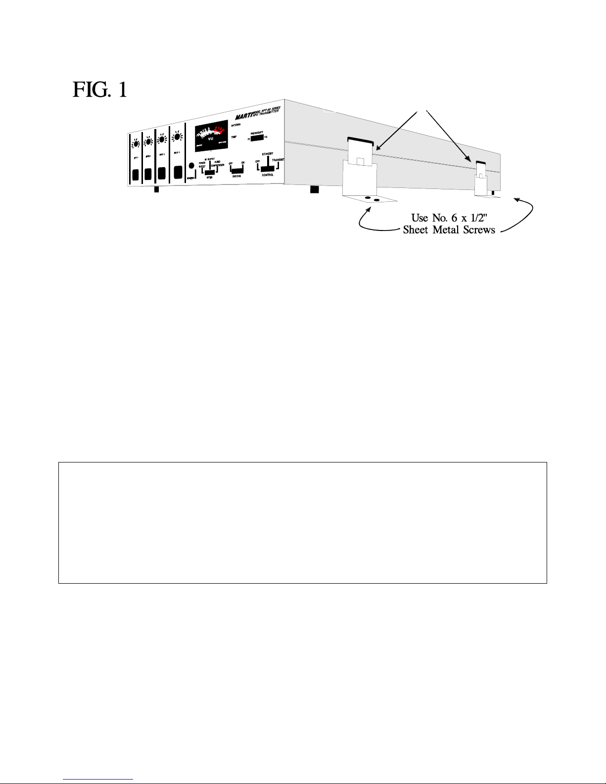
2. Hook the four mounting fasteners (in retracted position in the four slots on the sides of the transmitter. See Fig. 1.
(Fasteners are in Mobile Mounting Kit, 700-252-2).
3. Mark the location of the two mounting holes in each fastener bracket. Drill 7/64” diameter holes into the mounting
surface at the marked places for #6 x 1/2” sheet metal screws.
4. Attach the mounting fasteners with the sheet metal screws provided. Secure the transmitter with the fasteners.
Receiver Mounting
For mobile repeat using the Marti AR-10 Mobile Repeat Receiver, mount the receiver near the transmitter using the
three fasteners supplied in Mobile Mounting Kit, 700-252-2.
10
Page 17
8/7/2003
700-252-2
MOBILE MOUNT FASTENERS
SRPT-30/40A
Mobile Remote Control
Remote control of the SRPT-30/40A transmitter requires a switch to control primary 12-15 VDC power (or 15-30
VDC) and a second switch to control the transmit function. The primary 12-15 VDC (or 15-30 VDC) control
requirement can be met by tapping the ignition switch circuitry of the vehicle. The “transmit” function can be performed
by installing a switch on the vehicle.
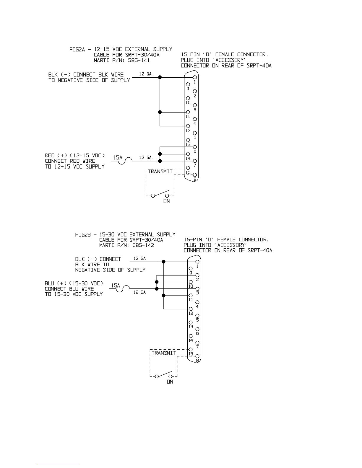
FIG. 2A and 2B show the electrical circuit of a mobile installation for 12-15 VDC (585-141) and 15-30 VDC (585-
142), respectively.
Mobile Repeat
Mobile repeat operation is covered under STATIONARY REMOTE BROADCAST INSTALLATION.
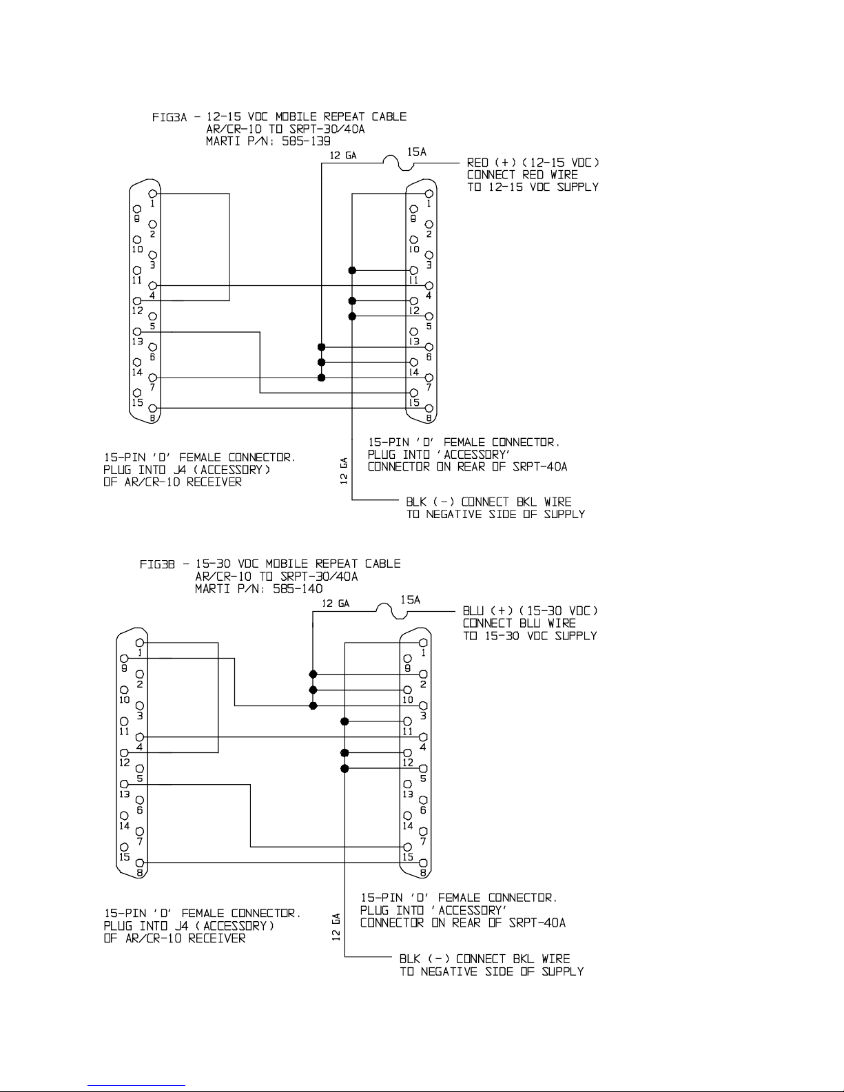
Electrical connection for a 12-15 Volt supply is made through Mobile Repeat Cable No. 585-139. This cable is
connected between the SRPT-30/40A transmitter and AR/CR-10 receiver. Power is obtained by connecting the fused
RED wire to the 12-15 VDC battery or supply. The supply must be capable of delivering 10 Amps minimum. The
electrical diagram of this cable is shown in FIG. 3A.
NOTICE
WHEN OPERATING THROUGH A CIGARETTE LIGHTER, THERE MAY BE A ONE TO TWO VOLT
DROP DUE TO THE LENGTH OF INTERNAL VEHICLE WIRING AND THE LARGE AMOUNT OF
CURRENT REQUIRED TO OPERATE THE SRPT-30/40A AT HIGHER OUTPUT POWERS.
THE SRPT-30/40A WILL OPERATE WITH AN EXTERNAL INPUT VOLTAGE AS LOW AS 7 VDC.
HOWEVER THE MAXIMUM RF OUTPUT POWER WILL DE-RATE LINEARLY AS THE EXTERNAL
INPUT VOLTAGE DROPS BELOW 12 VDC.
Electrical connection for a 15-30 Volt supply is made through Mobile Repeat Cable No. 585-140. This cable is
connected between the SRPT-30/40A transmitter and AR/CR-10 receiver. Power is obtained by connecting the fused
BLUE wire to the vehicle 15-30 VDC battery or supply. The supply must be capable of delivering 10 Amps minimum.
The electrical diagram of this cable is shown in FIG. 3B.
Automatic Morse Code Station Identifiers
The SRPT30/40A-450T TSL RPU’s are used for sending data back from a transmitter site to the studio (also known
as telemetry). In older FCC requirements, un-manned transmitters required an automatic remote control system to send
data back to the studio for verifying that the transmitter was operating properly. Many broadcasters today are still using
11
Page 18
8/7/2003
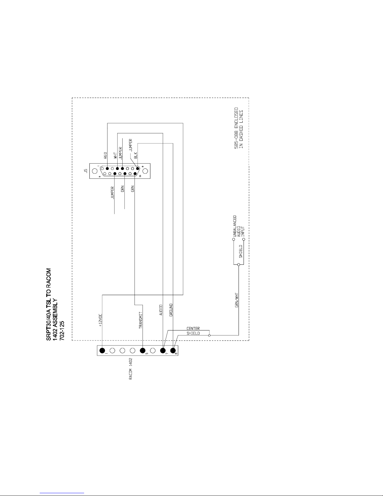
this system. Along with the data, a station identifier in morse code can also be input into the TSL. Marti typically uses
the RACOM MODEL 1402 Automatic Morse Code Station Identifier to accomplish this task. Marti stocks and sells the
RACOM 1402 (part number 565-006-1) along with the interconnecting cable (part number 585-088). Typically, the
cable is connected to the RACOM 1402 at the Marti facility. The customer can also connect up the cable as well. Refer
to Drawing 702-125.
Mobile Antenna Installation
One or more mobile antennas are required depending upon the various receive and transmit frequencies and whether
antenna duplexing is used. Antennas are specified in the various system packages listed in the Marti literature. The
installer should follow the instructions supplied with the mobile antennas.
12
Page 19
8/7/2003
13
Page 20
8/7/2003
14
Page 21
8/7/2003
Fixed Base Station and Repeater Installation
1. Install transmitter in standard rack by using Rack Mounting Kit No. 700-250-13 available from Marti.
CAUTION
ALLOW ONE PANEL SPACE ABOVE AND BELOW TRANSMITTER FOR INLET AIR-FLOW TO
INTERNAL FAN.
2. Connect transmitting antenna to ANTENNA connector on SRPT-30/40A rear panel.
3. Plug transmitter into a 3-prong, grounded 110-120 or 220-240 VAC outlet.
WARNING
FAILURE TO USE A PROPERLY GROUNDED OUTLET COULD RESULT IN A SAFETY HAZARD
OR FAULTY EQUIPMENT PERFORMANCE.
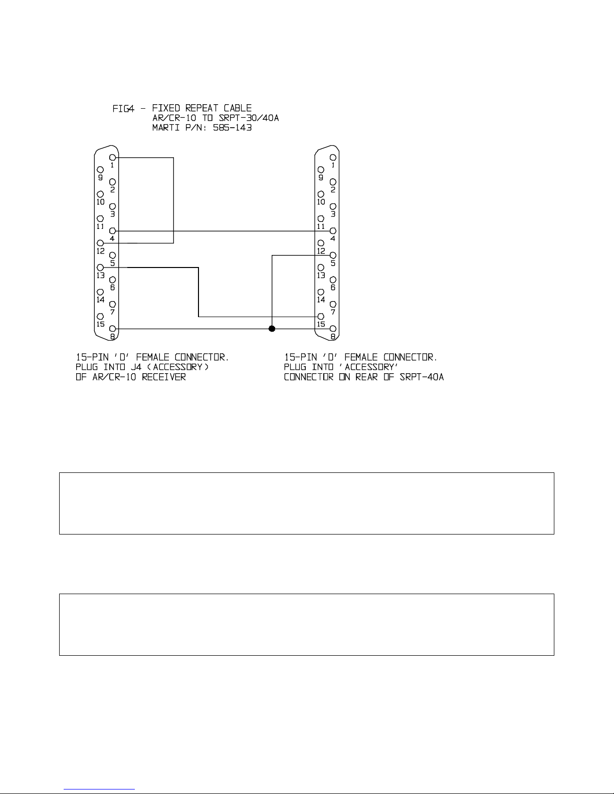
4. For fixed automatic repeater operation, connect Cable No. 585-143 (FIG. 4.) between accessory connectors of the
receiver and SRPT-30/40A transmitter. Connect receiving antenna to receiver J6 and transmit antenna to SRPT30/40A ANTENNA connector.
15
Page 22

8/7/2003
ANTENNAS
BASE STATION ANTENNA INSTALLATION CHECKLIST
The following suggestions are offered to help those responsible for antenna installations avoid
costly errors in assembly and adjustment. Marti Electronics assumes no responsibility for the
installation and performance of antenna systems associated with its equipment. The following
suggestions are not intended to be a complete step-by-step procedure, simply a listing of some of the
most frequently reported errors in antenna system installation.
Antenna Assembly
Follow the manufacturer's instructions carefully. If no instructions were included with the antenna, call or write the
antenna manufacturer for instructions. Antennas which have phasing or stacking cables must be assembled carefully to
avoid phase reversal or signal cancellation.
Transmission Line Connector Assembly
Do not use RG-58 U or RG-8 U cable for STL station antennas! They have too much loss at VHF and UHF
frequencies. Follow the instructions furnished by the manufacturer when cutting coaxial cable. Inspect the cable ends
for small metal fragments which can short-circuit the line inside the connector assembly. Check the line for a shortcircuit condition after each connector is installed by using an ohmmeter. Pressurized line should be checked for several
days under pressure before installation on a tower to ensure that there are no leaks in the line or fittings.
Moisture Proofing Coax Connectors and Fittings
Extreme care must be exercised with coaxial cable before and after connectors have been installed to ensure that
moisture does not enter the line. Foam dielectric line can take on moisture absorption which is difficult to detect and
remedy. Therefore, keep the line dry while in storage with ends tightly capped. Coaxial splices, connectors, and fittings,
to be located outside should be made mechanically tight, then coated with a weather-proofing material over at least two
layers of vinyl plastic electrical tape. Moisture problems in antenna systems are usually traced back to connectors which
have NOT been properly taped. The Marti K-1 Grounding and Weatherproofing Kit is recommended for use in each
new antenna installation.
Location and Grounding of Coaxial Cable
Keep the RPU receiver coaxial cable as far from the broadcast transmitter and its coaxial cable as possible.
WARNING
DO NOT STRAP RECEIVER CABLE TO THE MAIN ANTENNA CABLE AT ANY POINT.
PLACE THE RECEIVER ANTENNA COAXIAL CABLE ON THE OPPOSITE SIDE OF THE TOWER
FROM THE MAIN ANTENNA CABLE.
Maintain maximum separation between these cables at all points, including the distance from tower base to transmitter
building as well as inside the building.
16
Page 23

8/7/2003
System Grounding
It is essential that the RPU antenna system be properly grounded for safety and proper operation.
Antenna Installation and Adjustment
The polarization of the transmit and receive antennas of the RPU system must be the same! This means that if the
transmitting antenna is vertical, the receiving antenna must also be vertical. Each antenna should be attached to the
tower using the proper side mount or top mount hardware. If an RF wattmeter is available, each antenna and
transmission line can be checked for VSWR when the transmitter is supplying power to it. The VSWR should be less
than 1.5 to 1 (1.5:1).
If the antenna system fails to give the predicted signal strength level, the following
items should be checked:
1. Check for correct assembly of antenna.
2. Check that antennas have same polarity.
3. Check VSWR of both transmit and receive antennas. VSWR should be less that 1.5:1.
4. Check for obstructions in the path such as trees and man-made structures. The base antenna must be high enough to
provide a line-of-sight path to the remote transmitting antenna.
CAUTION & WARNING
YOU CAN BE KILLED IF AN ANTENNA COMES IN CONTACT WITH ELECTRIC POWER LINES
OR EXPOSED ELECTRICAL WIRING.
FOR YOUR SAFETY, USE EXTREME CAUTION WHEN IN-STALLING ANTENNAS.
KEEP AWAY FROM POWER LINES.
17
Page 24

8/7/2003
CONTROL, LED, & CONNECTOR
FUNCTIONS
ACCESSORY Input Connector
Audio Input:
When Input 4 is switched to “HI” level, audio can be fed into pins 4 and 5 of the ACCESSORY connector on the
rear of the transmitter. Input level should be between 0.2 volts to 2.0 volts rms. The output impedance of the device
connected to Input 4 should be 8 - 600 ohms. For unbalanced operation ground pin 5 to pin 1, 8, 11, or 12 and connect
audio to pin 4. Use standard 15-pin “subminiature D” female connector with cover.
Transmit Control:
“TRANSMIT” control can be accomplished remotely by a switch circuit connected between pin 15 and one of the
available ground pins (pin 1, 8, 11, or 12).
External DC supply:
The SRPT-30/40A can be powered externally by either a 12-15 Volt DC supply or a 15-30 Volt supply. If powered
off a 12-15 Volt supply, connect three positive leads of the supply to pins 6, 7, and 14. Connect three negative leads of
the supply to three ground pins (pins 1, 11, and 12). Each of the three positive leads and each of the three negative leads
should be an 18 gauge wire. You may also use one 12 gauge wire for each positive and negative leads and split the
stranded ends into three at the connector end.
ATTENTION
FOR 12-15 VOLT EXTERNAL SUPPLY, THE OPTIMUM VOLTAGE IS FROM 12 TO 15 VOLTS.
APPLYING A VOLTAGE LOWER THAN 12 VOLTS, WILL LIMIT THE MAXIMUM RF OUTPUT
POWER.
ALSO, THE EXTERNAL BATTERY OR POWER SUPPLY SHOULD BE CAPABLE OF HANDLING A
CONSTANT 10 AMPS. THERE WILL BE A DROP IN VOLTAGE ACROSS THE POWER CABLES.
THE POWER CABLES SHOULD BE AS SHORT AS POSSIBLE AND AS HEAVY GAUGE AS
POSSIBLE. EXPECT A COUPLE OF VOLTS DROP WHEN OPERATING THROUGH A CIGARETTE
LIGHTER.
If powered from a 15-30 Volt supply, connect three positive leads of the supply to three 15-30VDC pins (pins 2, 3,
and 10). Connect three negative leads of the supply to three ground pins (pins 1, 11, and 12). Each of the three positive
leads and each of the three negative leads should be an 18 gauge wire. You may also use one 12 gauge wire for each
positive and negative leads and split the stranded ends into three at the connector end.
ATTENTION
FOR 15-30 VOLT EXTERNAL SUPPLY, IF APPLYING A VOLTAGE LESS THAN 16 VDC, THE
SRPT-30/40A EXTERNAL B+ ADJUST POT ON THE TWO-STAGE RF POWER AMPLIFIER BOARD
SHOULD BE ADJUSTED TO ABOUT 12 VDC.
IF THIS IS THE CASE, THE MAXIMUM RF OUTPUT POWER COULD BE LIMITED.
18
Page 25

8/7/2003
CAUTION & WARNING
NEVER INSTALL AND CONNECT THE 12-15 VOLT AND THE 15-30 VOLT SUPPLIES AT THE
SAME TIME.
ALSO, NEVER CONNECT THE 15-30 VOLT SUPPLY TO THE 12-15 VOLT PINS AND NEVER
CONNECT THE 12-15 VOLT SUPPLY TO THE 15-30 VOLT PINS.
DOING SO MAY DAMAGE THE INTERNAL SWITCHING SUPPLY OR EITHER OF THE
EXTERNAL DC SUPPLIES.
CAUTION & WARNING
NEVER CONNECT THE SRPT-30/40A TO THE AC LINE AND EITHER OF THE EXTERNAL DC
SUPPLIES AT THE SAME TIME.
DOING SO MAY DAMAGE THE INTERNAL SWITCHING SUPPLY OR THE EXTERNAL DC
SUPPLY.
AC LINE Switch, AC Receptacle & Fuse
When the transmitter is not in use or if the SRPT-30/40A is to run off of an external supply, the AC LINE switch
should be in the “OFF” position.
When ready to use the SRPT-30/40A off of the AC line voltage, plug power cord into the AC Receptacle and switch
the AC LINE switch to the “ON” position.
The AC line fuse is rated at 2.5 amps.
WARNING
DO NOT PLUG INTO AC WITHOUT FIRST KNOWING THE POSITION OF THE AC INPUT SWITCH
LOCATED ON THE SIDE OF THE INTERNAL SWITCHING POWER SUPPLY.
SEE AC LINE INPUT SELECTION – 110-120 VAC OR 220-240 VAC SUB-SECTION IN THE
CALIBRATION AND ADJUSTMENTS SECTION FOR VERIFICATION AND CHANGING.
AFC LOCK LED
The AFC LOCK LED will either be flashing or solid green at all times, except during initial power up – and in that
case it will only be off for a few seconds.
When the SYNTHESIZER is searching for a frequency to lock on to and is therefore not locked, the AFC LOCK
LED will flash green. When the SYNTHESIZER finds and locks onto the frequency it was searching for, the AFC
LOCK LED will stay on, solid green. Three seconds after the SYNTHESIZER becomes locked, it will then be ready and
will enable the transmitter to output power.
19
Page 26

8/7/2003
In normal conditions, the SYNTHESIZER will not come “unlocked” unless sent a command to change to change to
a new frequency. However, other conditions can cause the SYNTHESIZER to come unlocked such as an AC line surge
or a sudden and very large change in VSWR. In those cases, the SYNTHESIZER will re-lock back on the assigned
frequency. The AFC LOCK LED will flash green until the SYNTHESIZER is locked. Once the SYNTHESIZER is
locked it will stay on, solid green.
ANTENNA Connector
Connection of various antenna systems is covered under INSTALLATION and ANTENNAS. It is only necessary
for the operator or announcer to see that the ANTENNA connector is tight and that the antenna is clear of objects which
may affect its radiation efficiency.
CAUTION & WARNING
THE ANTENNA CONNECTOR IS A TYPE “N” FEMALE CONNECTOR AND REQUIRES A MATING
TYPE “N” MALE CONNECTOR.
PLUGGING IN A “UHF TYPE (PL-259 OR SO-239)” INTO THE ANTENNA CONNECTOR WILL
DAMAGE AND SHORT OUT THE ANTENNA CONNECTOR. THIS COULD BURN UP THE PA
MODULE AND OTHER INTERNAL COMPONENTS.
ENCODE Switch
The internal subaudible encoder can be switched “ON” or “OFF” by the front panel switch. Encoding is used to
activate a repeater station, tape recorder, etc.
FREQUENCY SELECT Pushwheel Switches and EXECUTE Switch (SRPT-40A only)
Dial in the numbers that represent a frequency, channel number, or other command using the FREQUENCY
SELECT Pushwheel switches. Then press and release the EXECUTE switch to “send” the command numbers on the
FREQUENCY SELECT pushwheel switches to the internal controller to be decoded and executed. See the
OPERATION section for a listing and understanding of all commands.
F1/F2 Switch (SRPT-30 only)
Switching to the F1 position will cause the transmitter to lock onto the frequency that was configured at the factory
as “F1”. Switching to the F2 position will cause the transmitter to lock onto the frequency that was configured at the
factory as “F2”. The F1 and F2 frequencies are selected by the purchaser at the time of order.
AUDIO GAIN Controls
The GAIN potentiometer located above each input connector provides an independent level adjustment for that
input. Each GAIN potentiometer is adjusted as follows:
1. Connect input source at normal audio level.
2. Turn GAIN potentiometer to maximum counter-clockwise (“OFF”) position.
3. Place TRANSMIT/STANDBY switch in “STANDBY” position and allow METER pointer to reach 0 VU. Slowly
increase gain (clockwise) until METER begins deflecting to the left on audio peaks. Maximum deflection should be
-3 to -5 VU on the METER scale. This indicates 100% modulation of the transmitter. Excessive gain settings cause
high compression values which result in annoying increase in background noise. A 600 ohm headset may be
20
Page 27

8/7/2003
plugged into the MONITOR jack to aid in arriving at the proper gain adjustment. In high noise environments, close-
talk the microphone and reduce MIC gain until a maximum of -2 VU gain-reduction is indicated.
4. Once the proper gain level is determined, it will not be necessary to change it for that particular microphone or tape
player. The broadcast quality compressor/limited built into the unit will maintain modulation at the maximum level
while preventing over-modulation.
HIGH TEMP LED
When the internal controller detects a PA temperature between 85 and 100 degrees C, the HIGH TEMP LED will
flash red at a rate of once per second.
When the internal controller detects a PA temperature of greater than 100 degrees C, the RF output power will
completely shutdown, and the HIGH TEMP LED will flash red at a rate of twice a second. The RF output power will
stay shutdown until the PA temperature has dropped below 85 degrees C. When the internal controller detects that the
PA temperature is below 85 degrees C, it will turn off the HIGH TEMP LED and then enable the PA to transmit power.
A HIGH TEMP alarm could be due to the fan malfunctioning, the SRPT-30/40A placed in a closed-in area with
limited air circulation, or an experience of high VSWR.
HIGH VSWR LED
When the internal controller detects a VSWR of greater than 2 but less than 4, the HIGH VSWR LED will flash red
at a rate of once per second.
When the internal controller detects a VSWR of greater than 4 but less than 6, the output power will limit to a
maximum of half the rated power (that was set using the MAX PWR pot (R74) located on the synthesizer – see TUNE-
UP and ADJUSTMENTS section) and the HIGH VSWR LED will flash red at a rate of twice per second. When the
detected VSWR falls less than 4, the output will resume to it’s previous power setting, the HIGH VSWR LED will flash
at a rate of once per second if VSWR greater than 2, and will turn off if VSWR is less than 2.
When the internal controller detects a VSWR of greater than 6, or detects a reverse power of greater that one-third
the maximum rated output power, the output power will immediately shut off, the TRANSMIT LED will flash red, and
the HIGH VSWR LED will flash rapidly. Every three seconds the controller will attempt to turn on the transmit output
but will again shut down if the conditions have not changed. If this occurs, even if the operator turns off the TRANSMIT
switch, the HIGH VSWR LED will still flash rapidly. The only way to stop the HIGH VSWR LED from flashing, is to
repair the output (i.e., loose connection of output, wrong connector type, wrong cable, faulty antenna, short circuit cable,
etc…), and then turn the TRANSMIT switch on (if it was off), and after 3 seconds if the controller does not detect a very
high VSWR or high reverse power, the transmit output power will come on.
METER and METER SELECT Knob
When the METER SELECT Knob is either in the FORWARD POWER or REVERSE POWER position, the
corresponding measurement can be read off of the top "WATTS" scale of the METER.
When the METER SELECT knob is either in the PA CURRENT or the B+ position, the corresponding
measurement can be read off of the middle “VOLTS/AMPS” scale of the METER.
When the METER SELECT knob is in the AUDIO COMPRESSION position, the corresponding measurement can
be read off of the bottom “VU” scale of the METER.
21
Page 28

8/7/2003
MIC Input Connectors
These balanced inputs are for a 150 ohm dynamic microphone such as the Shure BG 1.0 with standard XLR-3 or
A3M connector. Microphone connections are given in INSTALLATION.
Input 4 can operate at MIC LEVEL or HIGH LEVEL by means of a SELECTOR switch inside the transmitter just
behind the Input 4 pot. The unit is factory selected for “HI” (HIGH) LEVEL balanced input for use with tape machines,
etc. To convert Input 4 to MIC (microphone) LEVEL, remove top cover and move switch to “MIC”.
MONITOR Jack
The MONITOR jack is active in “STANDBY” and “TRANSMIT” positions of the TRANSMIT/STANDBY
switch. A high-quality headset having 300 ohms or higher impedance can be plugged into the MONITOR jack to make
adjustments or to monitor the quality of the audio being transmitted. A miniature, single circuit, 1/8 inch, phone plug
should be used with the MONITOR jack.
POWER ADJUST Pot
When the SRPT-30/40A is transmitting, this pot can be adjusted to increase or decrease the output power from the
MAXIMUM power setting to almost zero Watts.
TRANSMIT LED
When the TRANSMIT/STANDBY switch is in the STANDBY position, the SRPT-30/40A will not transmit and
the TRANSMIT LED will be off.
When the TRANSMIT/STANDBY switch is in the TRANSMIT position but the SYNTHESIZER is not ready, the
SRPT-30/40A will not transmit and the TRANSMIT LED will flash red.
When the TRANSMIT/STANDBY switch is in the TRANSMIT position and the SYNTHESIZER is ready (which
is always three seconds after the SYNTHESIZER becomes locked), the SRPT-30/40A will transmit and the
TRANSMIT LED will be on, solid red.
TRANSMIT/STANDBY Switch
This switch is placed in “STANDBY” position to shut off the output power. The synthesizer will still be locked on
frequency as indicated by the solid AFC LOCK LED. The TRANSMIT/STANDBY switch is placed in the
“TRANSMIT” position when transmission is desired. The output power will turn on immediately at an output power that
correlates to the POWER ADJUST position. The TRANSMIT/STANDBY switch should be returned to the
“STANDBY” position as soon as a transmission is completed.
22
Page 29

8/7/2003
OPERATION
Connect up SRPT-30/40A to the AC Line Receptacle or External
DC Supply
CAUTION & WARNING
NEVER CONNECT THE SRPT-30/40A TO THE AC LINE AND EITHER OF THE EXTERNAL DC
SUPPLIES AT THE SAME TIME.
DOING SO MAY DAMAGE THE INTERNAL SWITCHING SUPPLY OR THE EXTERNAL DC
SUPPLY.
AC Line Operation
Position AC LINE switch to “OFF”, then plug SRPT-30/40A into a 110-120 VAC (if internal supply switched to
115) or 220-240 VAC (if internal supply switched to 230), grounded, 3-prong receptacle.
WARNING
DO NOT PLUG INTO AC WITHOUT FIRST KNOWING THE POSITION OF THE AC INPUT SWITCH
LOCATED ON THE SIDE OF THE INTERNAL POWER SUPPLY.
SEE AC LINE INPUT SELECTION – 110-120 VAC OR 220-240 VAC SUB-SECTION IN THE
CALIBRATION AND ADJUSTMENTS SECTION FOR VERIFICATION AND CHANGING.
WARNING
THIS EQUIPMENT MUST BE OPERATED WITH A 3-PRONG, GROUNDED, 110-120 or 220-240 VAC
RECEPTACLE!
FAILURE TO USE A PROPERLY GROUNDED OUTLET COULD RESULT IN A SAFETY HAZARD
OR FAULTY EQUIPMENT PERFORMANCE.
IF AN EXTENSION CORD IS USED, IT MUST BE THE THREE-WIRE GROUNDING TYPE TO
INSURE SAFETY.
DO NOT CUT OFF THE GROUND PIN OF A 3-PRONG PLUG!!
External DC Supply (12-15 Volt) Operation
Make sure that the SRPT-30/40A is not connected to an AC line. Place the front panel AC LINE switch in the ON
position. This turns off External DC Supply (12-15 Volt) to the unit.
23
Page 30

8/7/2003
The external supply or battery must be capable of delivering 8/10 Amps if running the SRPT-30/40A at maximum
output power. Connect up the unit using the Marti 585-141 12-15 VDC External Supply Cable. If choose to build your
own cable then follow the drawing on Figure 2A: Connect three positive leads of the supply to pins 6, 7, and 14 of a 15pin female D connector. Connect three negative leads of the supply to three ground pins (pins 1, 11, and 12) of the 15pin female D connector. Each of the three positive leads and each of the three negative leads should be an 18 gauge
wire. You may also use one 12 gauge wire for each positive and negative leads and split the stranded ends into three at
the connector end.
ATTENTION
FOR 12-15 VOLT EXTERNAL SUPPLY, THE OPTIMUM VOLTAGE IS FROM 12 TO 15 VOLTS.
APPLYING A VOLTAGE LOWER THAN 12 VOLTS, WILL LIMIT THE MAXIMUM RF OUTPUT
POWER.
ALSO, THE EXTERNAL BATTERY OR POWER SUPPLY SHOULD BE CAPABLE OF HANDLING A
CONSTANT 10 AMPS. THERE WILL BE A DROP IN VOLTAGE ACROSS THE POWER CABLES.
THE POWER CABLES SHOULD BE AS SHORT AS POSSIBLE AND AS HEAVY GAUGE AS
POSSIBLE. EXPECT A COUPLE OF VOLTS DROP WHEN OPERATING THROUGH A CIGARETTE
LIGHTER.
It is best to have an external switch between the external supply and the unit. Make sure the switch is in the open
position before connecting it to external supply. Otherwise make sure that when connecting the positive lead to the
external source that the 15-pin D connector is not connected to the SRPT-30/40A.
With the front panel AC LINE switch in the ON position, plug in the 15-pin D connector into the ACCESSORY
connector located in the rear of the SRPT-30/40A. Turn on external supply (if have a switch). With a voltmeter, measure
the voltage on the output of the external supply insuring that it is between 12 and 15 VDC. Switch the front panel AC
LINE switch to the OFF position. The unit should power up.
External DC Supply (15-30 Volt) Operation
Make sure that the SRPT-30/40A is not connected to an AC line. The front panel AC LINE switch does not control
the External DC Supply (15-30 Volt) operation. Therefore it does not matter what position it is in.
The external supply or battery must be capable of delivering 8/10 Amps if running the SRPT-30/40A at maximum
output power. Connect up the unit using the Marti 585-142 15-30 VDC External Supply Cable. If choose to build your
own cable then follow the drawing on Figure 2B: Connect three positive leads of the supply to three 15-30VDC pins
(pins 2, 3, and 10). Connect three negative leads of the supply to three ground pins (pins 1, 11, and 2). Each of the three
positive leads and each of the three negative leads should be an 18 gauge wire. You may also use one 12 gauge wire for
each positive and negative leads and split the stranded ends into three at the connector end.
It is best to have an external switch between the external supply and the unit. Make sure the switch is in the open
position before connecting it to external supply. Otherwise make sure that when connecting the positive lead to the
external source that the 15-pin D connector is not connected to the SRPT-30/40A.
Plug in the 15-pin D connector into the ACCESSORY connector located in the rear of the SRPT-30/40A. Turn on
external supply (if have a switch). With a voltmeter, measure the voltage on the output of the external supply insuring
that it is between 12 and 15 VDC. The unit should power up.
From 16 to 20 VDC, the SRPT-30/40A will transmit up to 50 Watts RF output. From 20 to 30 VDC the SRPT-40A
maximum output power will derate linearly down to 20 watts.
24
Page 31

8/7/2003
CAUTION & WARNING
NEVER INSTALL AND CONNECT THE 12-15 VOLT AND THE 15-30 VOLT SUPPLIES AT THE SAME TIME.
ALSO, NEVER CONNECT THE 15-30 VOLT SUPPLY TO THE 12-15 VOLT PINS AND NEVER CONNECT THE
12-15 VOLT SUPPLY TO THE 15-30 VOLT PINS.
DOING SO MAY DAMAGE THE INTERNAL SWITCHING SUPPLY OR EITHER OF THE EXTERNAL DC
SUPPLIES.
Connect up Antenna
Connect antenna to the ANTENNA connector on the SRPT-30/40A rear panel. Connection of various antenna
systems is covered under INSTALLATION and ANTENNAS.
CAUTION & WARNING
THE ANTENNA CONNECTOR IS A TYPE “N” FEMALE CONNECTOR AND REQUIRES A MATING
TYPE “N” MALE CONNECTOR.
PLUGGING IN A “UHF TYPE (PL-259 OR SO-239)” INTO THE ANTENNA CONNECTOR WILL
DAMAGE AND SHORT OUT THE ANTENNA CONNECTOR. THIS COULD BURN UP THE PA
MODULE AND OTHER INTERNAL COMPONENTS.
CAUTION
DO NOT TURN ON AC LINE OR EXTERNAL DC POWER UNTIL ANTENNA HAS BEEN
PROPERLY CONNECTED TO ANTENNA CONNECTOR!
Power-Up SRPT-30/40A
If using AC line, turn on SRPT-30/40A by turning on front panel AC LINE switch. If using 12-15 Volt or 15-30
Volt external DC supply, turn on SRPT-30/40A by turning on external DC supply. Refer to the External DC Supply
Operation procedure above for proper installation and operation.
The SRPT-30/40A will begin a power-up routine. The front panel meter will illuminate immediately. After about
three seconds the AFC LOCK LED will begin flashing green indicating that the synthesizer is searching for the last
frequency it was last locked on to.
If the TRANSMIT/STANDBY switch is in the TRANSMIT position, the TRANSMIT LED will flash red in unison
with the green flashing AFC LOCK LED. Once the synthesizer has found and locked onto the frequency, the AFC
LOCK LED will immediately stay on solid green and the TRANSMIT LED will continue to flash red for three
additional seconds. After the three seconds, the SYNTHESIZER will be ready, will enable the power amplifier to
transmit RF power, and the TRANSMIT LED will stay on solid red.
25
Page 32

8/7/2003
If the TRANSMIT/STANDBY switch is in the STANDBY position, the TRANSMIT LED and hence, the
transmitter RF power, will be off and will stay off even after the SYNTHESIZER has locked and the AFC LOCK LED
has illuminated solid green. When the TRANSMIT/STANDBY switch is placed in the TRANSMIT position (and three
seconds have elapsed since the SYNTHESIZER became locked) the PA will immediately begin transmitting and the
TRANSMIT LED will illuminate solid red.
Adjusting Output Power
Turn the METER CONTROL knob to the FORWARD POWER position and observe the forward power reading on
the top scale of the METER. Using a small flat-head screwdriver, adjust the POWER ADJUST pot (located about ¾ of
an inch behind the POWER ADJUST bezel ring) to adjust the forward power to a desired output power as indicated on
the METER.
What Frequency Will the SRPT-30/40A Power-Up on?
SRPT-30 Only:
The SRPT-30 will power-up on frequency F1 or F2 depending on the position of the F1/F2 front panel switch. The
frequencies corresponding to F1 and F2 were determined at the time of order and are hard coded within the synthesizer.
SRPT-40A Only:
The SRPT-40A will always power up on the last frequency it was locked onto before last power-down. If you’re not
sure what frequency the SRPT-40A will power up on, first make sure that the POWER ADJUST pot is at a minimum
(turned fully counter-clockwise) before powering up the SRPT-40A. After the SYNTHESIZER is locked and the
TRANSMIT/STANDBY switch is set in the TRANSMIT position, monitor the RF output with a frequency counter. If
necessary, increase the POWER ADJUST pot (turn clockwise) slowly until the frequency counter registers a frequency
reading.
WARNING
NEVER CONNECT THE FREQUENCY COUNTER DIRECTLY TO THE RF OUTPUT CONNECTOR
OF THE SRPT-30 OR SRPT-40A.
THE FREQUENCY COUNTER SHOULD BE COUPLED OFF OF AN RF COUPLER OR A WATT
METER.
EXCEEDING THE INPUT POWER RATING OF THE FREQUENCY COUNTER COULD DO
INTERNAL DAMAGE TO IT.
Inputting Audio
Plug in microphones (Inputs 1 - 3) or tape player (Input 4 internally switched to “HI” position; See MIC Input
Connections, above) and check operation by setting the METER CONTROL knob to the AUDIO COMPRESSION
position and observing the compression on METER and by a headset plugged into MONITOR jack. Set AUDIO GAIN
controls paragraph in the CONTROL & CONNECTOR FUNCTIONS section for how to adjust for no more than -3 VU
audio compression on the METER.
26
Page 33

8/7/2003
Changing Output Frequency Direct
SRPT-30 Only:
Simply change the position of the F1/F2 front panel switch and the unit will change to the corresponding frequency.
SRPT-40A Only:
To change the frequency of the SRPT-40A, the S1 dip-switches on the Front Panel Control & Meter board (800385A) behind the front panel (see the SRPT-40A Adjustment Locations) need to be set with switches 1 and 2 in the
“ON” position and switches 3 and 4 in the “OFF” position. These positions are the normal position and are set at the
factory, so there should be no need to remove the top cover.
When the S1 switches are set as described in the last paragraph, then all that is required is to enter the desired
frequency from left to right into the FREQUENCY SELECT pushwheel switches and then press and release the
EXECUTE pushbutton switch.
All seven digits on the front panel FREQUENCY SELECT pushwheel switches must be entered. The frequency is
entered in MHz where the first three digits represent the left side of the decimal place, and the last four digits represent
the right side of the decimal place. For example, the frequency 450.0125 MHz will simply be entered as 4500125.
If a valid frequency is entered and the EXECUTE pushbutton is pressed and released, then the RF output power will
immediately turn off (if it was on to begin with) and the SYNTHESIZER will go through it’s normal routine in searching
and locking onto the requested frequency. When the frequency is found, the AFC LOCK LED will stop flashing and
illuminate solid green. After three seconds the TRANSMIT LED will stop flashing and illuminate solid red (assuming
the TRANSMIT/STANDBY switch is in the TRANSMIT position) and the SRPT-40A will resume transmitting at the
new frequency and at the same output power it was before leaving the previous frequency.
What is A Valid Output Frequency?
A valid output frequency is defined as a frequency that operates within the model bandwidth and is either a standard
frequency, or is a non-standard frequency that falls within ±.00015% of the requested frequency. A standard output
frequency is one that is divisible by 5 or 6.25 KHz for 450 band models and less, and divisible by 10 or 12.5 KHz for
greater than 450 band models. All other frequencies are considered non-standard frequencies. The SRPT-30/40A will
lock on standard output frequencies within a ±.00004% tolerance. The SRPT-30/40A will lock on about 95% of nonstandard frequencies. The tolerance of these frequencies fall within ±.00015% of the requested frequency. If the
synthesizer determines that the non-standard frequency will fall outside ±.00015% of the requested frequency, then this
is considered an invalid frequency and it will not change to the requested frequency.
SRPT-30 Only:
There are only two frequencies to choose from, F1 and F2, as configured at the factory, and are always considered
valid. However, at the time of order, if the customer requires a frequency that is not divisible by 5 or 6.25 KHz (or by 10
or 12.5 KHz for > than 450 MHz models), we can determine immediately whether or not the requested frequencies will
fall within ±.00015% tolerance. If one or both frequencies do fall not within this tolerance, then the order will be
considered special and must be determined by the engineering department at Broadcast Electronics if we can tune to the
required frequencies.
SRPT-40A Only:
If an invalid frequency is entered in, or if the same frequency that the SRPT-40A is currently locked on to is entered
in, then the SRPT-40A will remain at its current frequency, i.e., nothing will happen. If the operator desires to change to
a frequency that is invalid, he must choose the closest valid frequency and then manually tune the reference oscillator on
the synthesizer to get to desired frequency. However, if the operator tunes the reference oscillator to get to an invalid
frequency, then when needing to change to another frequency (valid or non-valid), the operator may have to retune the
reference oscillator again.
27
Page 34

8/7/2003
Changing Output Frequency via Channel Select – SRPT-40A
Only
The frequency can also be changed by entering a channel number that was previously stored with a frequency. See
Storing Output Frequencies into Channels for instructions on how to store frequencies. There are ten channels
available for storing and recalling frequencies. These ten channels are preset with default or customer requested
frequencies at the factory.
To change frequency via channel select, the S1 dip-switches behind the front panel must be set with switches 1 and
2 in the “ON” position and 3 and 4 in the “OFF” position. These are the default positions and are in the same position as
when changing the frequency direct. So there’s no need to remove the top cover.
Now you’re ready to enter the channel. This is done by setting the six left-most digits (digits 2-7) of the
FREQUENCY SELECT pushwheel switches equal to zero. Then the far right digit (digit 1) is set to the channel of
choice (channel 0 – channel 9). After entering the channel, press the EXECUTE pushbutton down and then release. The
SYNTHESIZER will change to the frequency that was stored in the channel.
WARNING
THE REMAINING OPERATIONS ARE FEATURES THAT REQUIRE SETTING INTERNAL DIP-
SWITCHES.
IN ALL CASES, WHEN PERFORMING THESE OPERATIONS, THE SRPT-40A MUST BE ON AND
THE TOP COVER MUST BE REMOVED.
WHEN THE OPERATION IS COMPLETE, ALWAYS SET THE INTERNAL S1 DIP-SWITCHES WITH
SWITCHES 1 AND 2 “ON” AND SWITCHES 3 AND 4 “OFF”. THEN RE-INSTALL THE TOP COVER.
Storing Output Frequencies into Channels – SRPT-40A Only
The SRPT-40A must be locked on a frequency before storing that frequency into one of the ten available channels.
It is not necessary, however, that the SRPT-40A be transmitting, hence the TRANSMIT/STANDBY switch can be in
STANDBY.
First, lock on to the desired frequency either directly or via channel select. Remove the top cover of the SRPT-40A.
Set the S1 dip-switches (located behind the front panel) as follows: Switches 1, 3, and 4 set to the “OFF” position and
switch 2 set to the “ON” position.
Next, set the six left-most digits (digits 2-7) of the FREQUENCY SELECT pushwheel switches equal to zero. Then
the far right digit (digit 1) is set to the channel of choice (channel 0 – channel 9) to be stored. After entering the channel,
press the EXECUTE pushbutton down and then release. The current frequency-in-lock will be stored in the selected
channel and the SRPT-40A will remain at its current frequency. If you need to store more channels, repeat the steps in
this paragraph.
Finally, put the S1 dip-switches back to where they were, i.e., switches 1 and 2 in the “ON” position and switches 3
and 4 in the “OFF” position. Re-install the top cover.
28
Page 35

8/7/2003
It would be a good idea to test the stored channel(s) by changing the frequency to some other frequency and then
recalling the stored channel(s).
Control Switch Settings – SRPT-40A Only
Control Switch Settings enable or disable important controls used in the SRPT-40A. These control settings include
the following:
Power Adjust Pot
HiHi VSWR Foldback
Reverse Power Calibration
Forward Power Calibration
HiHi Temperature Shutdown
Direct Frequency Change
Channel Frequency Change
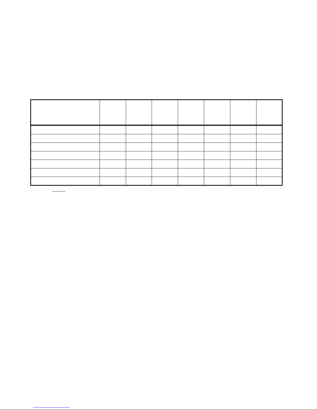
Refer to TABLE (1) - Control Switch Settings Command for disabling or enabling the desired controls. Remove
the top cover. Set the internal dip-switch S1 switches and the FREQUENCY SELECT pushwheel decimals as outlined
in Table (1). The entries in BOLD are default settings from the factory
When all FREQUENCY SELECT pushwheel decimals have been set to their required values that correspond to the
desired control switch setting, you must send the command by pressing the EXECUTE pushbutton down and then
releasing. The internal controller will enable or disable the control. Set the internal dip-switch S1 back to its normal
position with switch 1 and 2 “ON” and switch 3 and 4 “OFF”. Re-install top cover.
Following is a description of the control settings:
Power Adjust Pot – The default for this setting is “enabled” which allows the user to change the power from almost
0 Watts to the maximum RF output power setting via the front panel POWER ADJUST pot. Refer to the Maximum
Power Setting paragraph in the CALIBRATION AND ADJUSTMENTS section of this manual for information on
how to set the maximum power. If this user “disables” this setting, then the RF output power will maintain where last set
and tuning of the POWER ADJUST pot will have no effect.
HiHi VSWR Foldback – The default for this setting is “enabled”. This means when a VSWR is detected greater than
4, the power will limit to one-half the maximum power setting. If VSWR foldback is “disabled”, then the forward RF
power will not try to foldback, even when the controller detects a VSWR of greater than 4. The HIGH VSWR LED will
still flash however. For maintaining long life from the power amplifier, it is not recommended to disable VSWR
Foldback.
Reverse Power Calibration – The default setting for this setting is “disabled”. This setting should only be “enabled”
during calibration (see the Reverse Power Calibration paragraph in the CALIBRATION AND ADJUSTMENTS
section).
Forward Power Calibration – The default setting for this setting is “disabled”. This setting should only be
“enabled” during calibration (see the Forward Power Calibration paragraph in the CALIBRATION AND
ADJUSTMENTS section).
HiHi Temperature Shutdown – The default for this setting is “enabled”. See High Temp LED paragraph in the
CONTROL & CONNECTOR FUNCTIONS section for complete description. When enabled, the power amplifier
will shut down when the PA temp reaches 100 degrees C. If “disabled”, then the power amplifier will not shutdown due
to HiHi temperature but the HIGH TEMP LED will still flash. Again, for maintaining long life from the power amplifier,
it is not recommended to disable High Temperature Shutdown.
Direct Frequency Change – The default for this setting is “enabled” to be able to change the output frequency
direct. If “disabled”, then attempting to change the output frequency will be ignored by the internal controller. This
29
Page 36
8/7/2003
setting is useful for locking out anyone from changing frequencies, or to change frequencies via user programmed
channels.
Channel Frequency Change – The default for this setting is “enabled” to be able to change the output frequency by
channel select. If “disabled”, then attempting to change the output frequency by selecting channels will be ignored by the
internal controller. This setting is typically “disabled” if the Direct Frequency Change setting is also disabled. In that
case, only one frequency can ever be transmitted.
TABLE 1 - Control Switch Settings Command
CONTROL SETTING DIGIT
#7
(far left
digit)
Power Adjust Pot 1400
HiHi VSWR Foldback 1200
Reverse Power Calibration1100
Forward Power Calibration1040
HiHi Temperature Shutdown1020
Direct Frequency Change 1000
Channel Frequency Change1000
DIGIT
#6
DIGIT
#5
DIGIT
#4
DIGIT
#3
ENB/DIS
ENB/DIS
ENB/DIS
ENB/DIS
ENB/DIS
ENB/DIS
ENB/DIS
DIGIT
#2
00
00
00
00
00
20
10
DIGIT
#1
(far right
digit)
Notes:
Internal Dip-Switch (S1): Switch 1, 3, and 4 are “OFF”; Switch2 is “ON”
ENB (Enable) = 1, DIS (Disable) = 0
Bold selection indicates factory default setting
30
Page 37

8/7/2003
THEORY OF OPERATION
Refer to Block Diagram Drawing No. 702-124, 702-117, and appropriate Schematic Diagrams.
CIRCUIT BOARD DESCRIPTION
PRE-AMP/MIXER Board, 800-251A
Each of the four microphone inputs is fed to a low-noise differential op-amp (half of an NE-5532). Critical resistors
in the input circuits are low-noise, precision, temperature stable types to obtain maximum performance from the preamps. Monolithic chip capacitors are used to filter RF voltages that may be present at the microphone inputs. The four
op-amp outputs are fed to gain pots then resistively mixed and routed to the COMPRESSOR BOARD.
COMPRESSOR Board, 800-166A (SRPT30/40A-xxx: uses 800-166A40A;
SRPT30/40A-450T: uses 800-166A40ATSL)
Several functions are performed on this board. Integrated Circuit IC-1 serves as a (a) pre-amp (not used on the
SRPT-30/40A), (b) pre-emphasis amplifier, (c) voltage-controlled attenuator, and (d) regulator /ripple rejection. Preemphasized audio out of IC-1B is also fed to D2 - D3 which form an adjustable series peak-limiting circuit. This circuit
is adjusted to limit only audio peaks which get past the compressor. The limiter circuit feeds a low-pass filter (L1, C23,
and R46) which reduces the audio bandwidth to that specified for the operating channel of the transmitter. To this is
mixed the output of the tone encoder, IC-2A, which is a low-distortion Wien bridge oscillator. This composite signal is
then fed to the Modulation port (on P2) of the Transmitter Synthesizer Board, 800-375AT. This audio signal is also fed
to IC-2B which amplifies it to a level suitable for a 600 ohm headphone monitor. IC-2C is a DC amplifier the input of
which is connected to the AGC (automatic gain control) circuit and the output of which drives the audio compression
meter.
14.5 VOLT STEP-UP REGULATOR Board, 800-392A
The 800-392A is a DC/DC converter that powers the synthesizer, audio, and mixer boards. It allows the user to
apply an external input voltage (through the 12-15 VDC accessory input pins) as low as 7 VDC and still maintain 14.5
volts to the synthesizer and 10.0 volts to the audio and mixer boards. Therefore, the synthesizer will stay locked during
most power surges and excessive voltage drops. The 800-392A also suppresses any external (or internal) voltage noise
such as an alternator from a running vehicle. As a result, the SRPT-30/40A still maintains a high signal-to-noise.
TRANSMITTER SYNTHESIZER Board, 800-375AT
The fundamental purpose of this board is to accomplish two things: (1) Generate the final output frequency and (2)
FM modulate the mixed audio. The circuitry to achieve this consists of a Phase-Locked Loop (PLL), which includes a
Frequency Synthesizer IC, Voltage-Controlled Oscillator, a pre-scaler, a reference frequency oscillator, and a lowfrequency loop filter. The Frequency Synthesizer IC is a programmable device for setting internal counters for allowing
the reference frequency oscillator to be a perfect multiple of the final output frequency. The reference frequency
oscillator is a 12.8 MHz TCXO. The low-frequency loop filter is a one-Hertz active type. The 64/128 pre-scaler is used
to help aid in the multiplying.
The audio output from the 800-166 COMPRESSOR board is fed into the TRANSMITTER SYNTHESIZER’s VCO
which FM modulates the signal at the final output frequency. This modulated RF output signal is then sent to the 800388A Two-Stage RF PA board for final amplification.
Included on the TRANSMITTER SYNTHESIZER board is a high-speed microcontroller. This controller decodes
and acts on commands sent from the Front Panel Control & Meter board (800-378A). These commands include new
frequency change (direct or channel select), control switch settings, calibration, etc. The controller also monitors and
regulates forward power, monitors VSWR and PA temperature, performs auto foldback of power due to high VSWR
and then recovers when VSWR lowers, and performs auto shutdown of power due to very high temp. It has internal
EEPROM for storing important information such as frequency channels and historical info. The controller also detects
synthesizer lock and unlock as well as enabling a fastlock feature for far frequency changes.
31
Page 38

8/7/2003
FRONT PANEL CONTROL & METER Board, 800-389A (800-382A – some models) –
SRPT-30 only
This board does the following:
- Sends F1/F2 state to TRANSMITTER SYNTHESIZER,
- Displays LED alarm information received from the TRANSMITTER SYNTHESIZER,
- Receives and decodes digital data from TRANSMITTER SYNTHESIZER for forward and reverse power
readings and converts to analog signals,
- Directs POWER ADJUST analog signal to TRANSMITTER SYNTHESIZER,
- Multiplexes all analog metering signals via METER SELECT knob for independently monitoring on METER,
- Sends state of the TRANSMIT/STANDBY switch.
FRONT PANEL CONTROL & METER Board, 800-385A (800-378A – some models) –
SRPT-40A only
This board does the following:
- Collects and sends commands from the front panel pushwheel switches to the on-board microcontroller of the
TRANSMITTER SYNTHESIZER board,
- Displays LED alarm information received from the TRANSMITTER SYNTHESIZER,
- Receives and decodes digital data from TRANSMITTER SYNTHESIZER for forward and reverse power
readings and converts to analog signals,
- Directs POWER ADJUST analog signal to TRANSMITTER SYNTHESIZER,
- Multiplexes all analog metering signals via METER SELECT knob for independently monitoring on METER,
- Sends state of the TRANSMIT/STANDBY switch.
TWO-STAGE RF POWER AMPLIFIER Board, 800-388A (800-373A – some models)
The RF output signal (50 mW max) from the TRANSMITTER SYNTHESIZER is fed into this TWO-STAGE RF
POWER AMPLIFIER board. The RF goes through two stages of RF amplification. The first stage (U2) is a 1-Watt
(max) pre-driver. It has an input and output transformer (T1 and T2) for achieving optimum 50 Ohm matching between
the stages. The output of T2 is fed into the final PA module (U3) for an output of up to 60 Watts max. This PA module
usually has a lower RF output for SRPT-30’s. The signal is then low-passed filtered through FL1 and then fed through a
directional coupler for monitoring forward and reflected power. An Automatic Power Control (APC) circuit residing on
the TRANSMITTER SYNTHESIZER board stabilizes and maintains an accurate output power level by comparing it to
a reference power level which is set by the user via the front panel POWER ADJUST pot. The APC circuit samples the
forward power via the coupled forward power on PA board.
This board also provides regulated B+ for powering the PA and the rest of the chassis when using 15-30 Volts
external supply. Finally, there also exist circuitry for regulating the fan, measuring PA temperature, and monitoring PA
current.
SWITCHING POWER SUPPLY, 800-383A (800-324A – some models)
The Switching Power Supply accepts input from 110-120 or 220-240 VAC and supplies 15 VDC and up to 10
Amperes to power the SRPT-30/40A. The power supply must be switched to the appropriate 115 or 230 position. This is
usually done at the factory.
RPU TRANSMITTER I/O Board, 800-379AR
This board passes and distributes external power supply input via the back-panel ACCESSORY connector. It also
passes and directs the ENCODE, TX REM CNTL, and external audio signals. All signals are LC filtered.
32
Page 39

8/7/2003
RF SYSTEM & CONTROL
Refer to Block Diagram Drawing 702-117. The fundamental RF generation of the SRPT-30/40A takes place on the
TRANSMITTER SYNTHESIZER board in a circuit known as a Phased-Locked Loop (PLL). The final output
frequency (Fout) is generated by the Voltage Controlled Oscillator (VCO). Fout is determined by the Reference
Frequency (Fr) and N by the relation: Fout = Fr x N.
N is made up by the internal n and a counters of the Frequency Synthesizer IC and by P, the divide-by-128
prescaler. The value N is equal to: N=n x P + a. We can now write Fout in the form: Fout = Fr x (n x P + a).
Therefore, with P as a constant value of 128, the n and a counters can be programmed in such a way that the output
frequency Fout will always be an integer multiple of the Reference Frequency, Fr. The a-counter will always be a
number from 0 to 128, and the n-counter will be a number from 1 to 1023.
The Reference Frequency, Fr, is generated by the 12.8 MHz TCXO (Temperature Controlled Crystal Oscillator)
and the internal R-counter of the Frequency Synthesizer IC. This relation is simply: Fr = Fosc / R, where Fosc = 12.8
MHz and R is the programmable R-counter.
The desired output frequency and the Reference Frequency information is sent from the operator via the front panel
to the microcontroller. The microcontroller will set the n and a-counters to yield the requested output frequency, and will
set the R-counter to yield the requested Reference Frequency. The Reference Frequency is rarely changed, so typically,
Fref is treated as a constant and only the output frequency is changed.
The output frequency is modulated by the injected audio at the input of the VCO. The amount of modulation is
determined by the Modulation setting. The VCO will alter the output frequency in deviation and rate corresponding to
the amplitude and rate (frequency) of the input voltage signal (audio). This is commonly known as frequency modulation
(FM). Since the loop filter has a low frequency response (1 Hz), the PLL will not track the modulated signal and as a
result, only the VCO output will change.
The RF power and power control circuit is shared by the TRANSMITTER SYNTHESIZER and the TWO-STAGE
RF POWER AMPLIFIER. The output of the VCO is sent to a controlled amplifier and is then sent to the TWO-STAGE
RF POWER AMPLIFIER for final amplification. To maintain a steady and constant RF output (over temperature and
voltage changes), a sample of the RF output power (Forward coupling) is sent to the Automatic Power Control (APC)
circuit and compared to a reference output power setting. Any delta changes are instantly compensated for in the APC
circuit and an adjustment is made in the controlled amplifier. A MAX POWER setting can be user adjusted to limit the
final RF output power.
The low-pass filter (LPF) following the final amplifier will filter out all spurious harmonics to a level lower than –
60 dB. The Reverse coupling samples any return power and is sent to the microcontroller. Since the Forward coupling is
also sent to the microcontroller, the VSWR can be determined. The microcontroller will “foldback” the output power if
the VSWR exceeds a value of 4. Finally, all front panel alarms and indicators are sent from the microcontroller.
33
Page 40
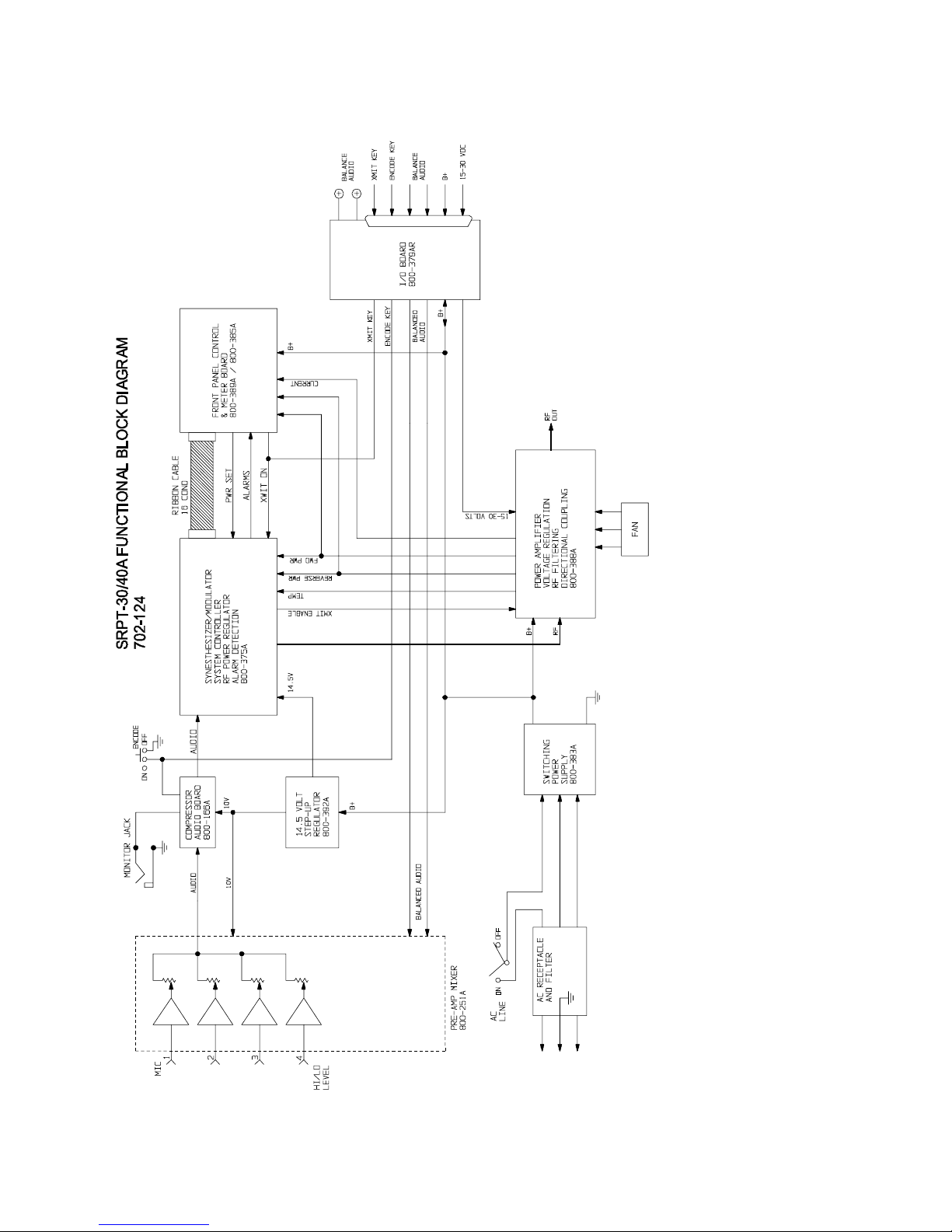
8/7/2003
34
Page 41
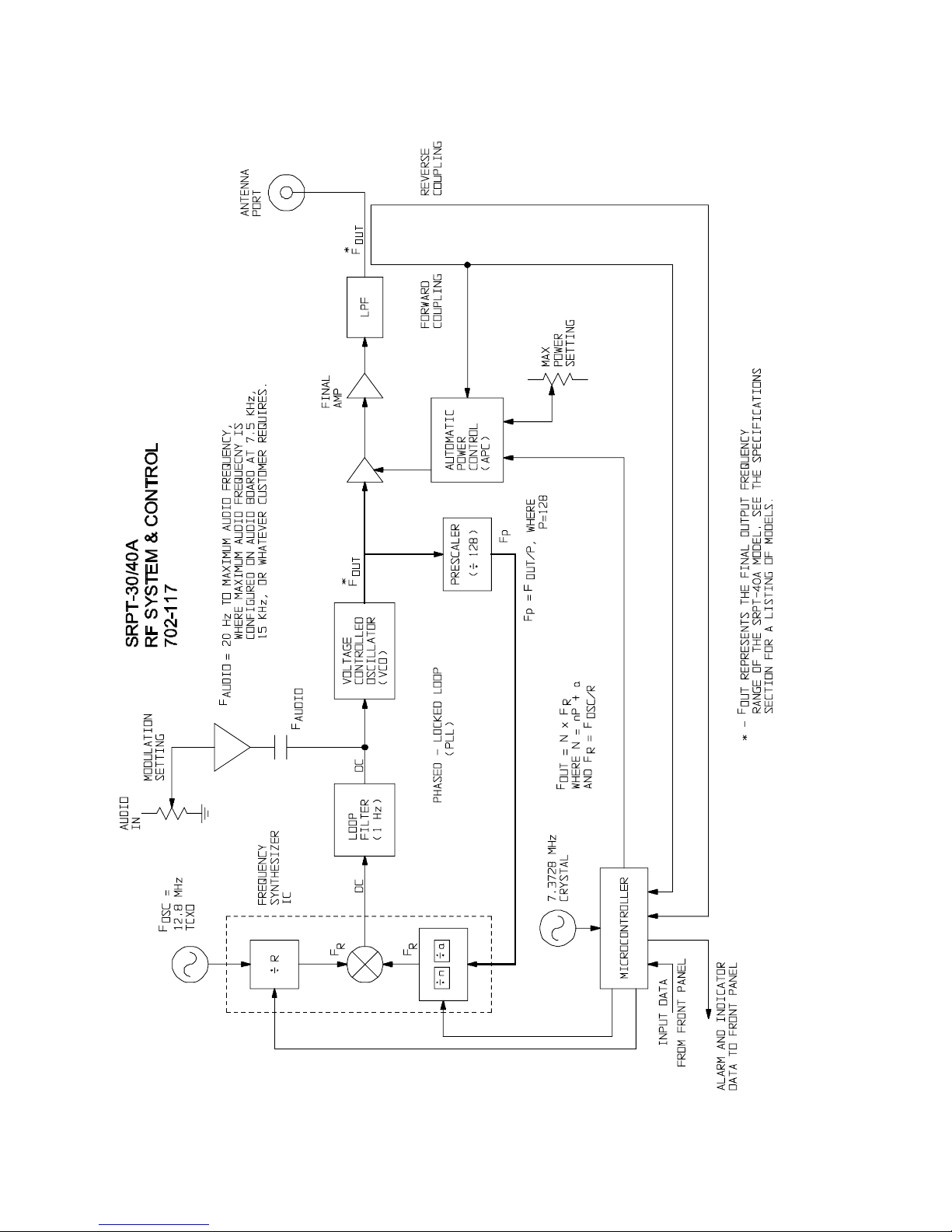
8/7/2003
35
Page 42

RECOMMENDED TEST
EQUIPMENT
Distortion Analyzer Krohn-Hite Model 6801
Oscillator Krohn-Hite Model 4500
Attenuator Set Hewlett-Packard Model 3500
Frequency Counter Hewlett-Packard Model 5383A
(option 001)
Digital Multimeter Beckman Model 3030
Analog Multimeter Triplett Model 630
RF Attenuator adjustable 0-110 dB
RF Signal Generator Marconi Model 2022C
Spectrum Analyzer Hewlett-Packard Model 8558B
Wattmeter (50 ohms impedance) Bird Model 43
5 or 50 watt element 100-250 MHz or 400-1000 MHz, Bird
Automatic Modulation Meter Wavetek Model 4101
50 watt RF Load Microwave Associates Model 44003
Stereo Monitor Belar Model FMS-2
Stereo Generator Aphex Model AX400
Oscilloscope Tektronix Model 2215
8/7/2003
TOOLS FOR ALIGNMENT
Tuning Tool GC 9300
Tuning Tool GC 9440
Tuning Tool Spectrol 8T000
Tuning Tool Sprague-Goodman
Screwdriver Xcelite R184, 1/8” x 4”
36
Page 43

8/7/2003
SRPT-30/40A TRANSMITTER
FACTORY TEST REPORT
Customer: ________________________ Address: _______________________________________
Serial No.: __________ _______________________________________
____Set internal switching power supply = 13.0 Volts
____Program synthesizer
____Frequency measurement, adjust, and changing
____Forward power calibration and metering
____Reverse power calibration and metering
____Current metering calibration
____Verify B+ metering
____Audio board limiter set
____Audio compressor meter set to 0 VU
____Signal to noise within specifications
____Frequency response within specifications
____Distortion within specifications
____Set deviation to _____kHz corresponding to 100% modulation
____Set encode frequency to 27 Hz
____Set encode frequency deviation to 600 Hz
____Test 12-15 VDC external supply and low-voltage dropout
____Calibrate internal regulator and test 15-30 VDC external supply
____Test accessory functions
24-Hour Burn-in: Start: Date_________ Time_________
Stop: Date_________ Time_________
____Fine tune frequency adjust at ________MHz
____Max power adjust to ______Watts
Customer Specific Settings (if different from standard):
Encode deviation________ Audio response________ Max power________
Channel settings (SRPT-40A only - upon request):
CH0:________MHz CH1:________MHz CH2:________MHz CH3:________MHz
CH4:________MHz CH5:________MHz CH6:________MHz CH7:________MHz
CH8:________MHz CH9:________MHz
____Frequency change disabled (SRPT-40A only)____Channel change disabled (SRPT-40A only)
DATE:_____________ SIGNATURE:__________________________________
37
Page 44

8/7/2003
CALIBRATION AND
ADJUSTMENTS
Refer to Location of Adjustments Drawing No. 702-122 and appropriate schematic
diagrams for each module.
This equipment was thoroughly tested and inspected at the factory prior to shipment. The actual
equipment performance was recorded on the SRPT-30/40A TRANSMITTER FACTORY TEST
REPORT. Adjustments should rarely be necessary in the field and should be attempted only by
highly trained technicians familiar with this type of equipment. Laboratory grade test equipment is
required and is listed under TEST EQUIPMENT AND TOOLS. For location of adjustments and test
points in the SRPT-30/40A Transmitter refer to Adjustment Location Diagram, 702-122.
NOTE
FOR ALL ADJUSTMENTS, REMOVE THE TOP COVER FROM THE SRPT-30/40A CHASSIS.
REPLACE THE COVER WHEN THE ADJUSTMENT PROCEDURE IS COMPLETE.
AC Line Input Selection - 110-120 VAC or 220-240 VAC
WARNING
ON FIRST TIME USAGE, WE RECOMMEND THAT THE OPERATOR VERIFIES THAT THE AC
INPUT SELECTOR SWITCH IS IN THE POSITION THAT CORRESPONDS TO YOUR AC INPUT
REQUIREMENTS.
1. Remove AC line voltage from SRPT-30/40A.
2. Remove the 800-166A COMPRESSOR AUDIO board.
3. View the side of the 800-383A Switching Power Supply as shown. For 110-120 VAC applications, the switch
should read “115” and positioned toward the front of the unit. For 220-240 VAC applications, the switch
should read “230” and positioned toward the back of the unit.
4. If the switch position is not in your required position, take a small flat-head screwdriver and switch the AC
INPUT switch to the required position.
5. Replace the 800-166A COMPRESSOR AUDIO board.
Switching Power Supply Voltage Adjustment
The input to the switching power supply can be from 110-120 or 220-240 VAC, 50/60 Hz. The DC B+ output,
measured off of one of the red wires of the switching supply, can be slightly adjusted at B+ ADJUST. The recommended
B+ reading should be 13.0 volts.
38
Page 45

8/7/2003
B+ Adjustment When Using 15-30VDC External Supply
CAUTION
THIS ADJUSTMENT HAS BEEN SET AT THE FACTORY AND SHOULD NOT REQUIRE ANY
FURTHER ADJUSTMENTS.
1. Remove AC line voltage from SRPT-30/40A.
2. Connect up external supply to the 15-30VDC pins of the AUXILLARY connector (see the ACCESSORY Input
Connector paragraph in the CONTROL & CONNECTOR FUNCTIONS section).
3. Switch the AC LINE front panel switch to the “OFF” position.
4. Turn on external supply and adjust to approximately 18 VDC.
5. Using a VOLT METER, with negative lead connected to ground (chassis), connect the positive lead to one of the
red wires connected to the 800-379AR I/O board.
6. On the TWO-STAGE RF POWER AMPLIFIER board adjust EXTERNAL B+ ADJUST (pot R5) in the direction
required to achieve a B+ reading of 13.0 to 13.5 Volts. This voltage should be adjusted with the
TRANSMIT/STANDBY switch in “STANDBY” position.
WARNING
IF THE 15-30 VOLT SUPPLY IS LESS THAN 16 VOLTS, THE EXTERNAL B+ ADJUST SHOULD BE
SET TO 12 VOLTS.
THIS MAY LIMIT THE MAXIMUM OUTPUT POWER.
Frequency Measurement
The RF output frequency of this transmitter should be measured as often as necessary to insure on-frequency
operation and to comply with regulations. Monitor the RF output with a frequency counter via an RF coupler or Watt
meter.
WARNING
NEVER CONNECT THE FREQUENCY COUNTER DIRECTLY TO THE RF OUTPUT CONNECTOR
OF THE SRPT-30/40A.
THE FREQUENCY COUNTER SHOULD BE COUPLED OFF OF AN RF COUPLER OR A WATT
METER.
EXCEEDING THE INPUT POWER RATING OF THE FREQUENCY COUNTER COULD DO
INTERNAL DAMAGE TO IT.
39
Page 46

8/7/2003
Frequency Fine-Tune Adjust
CAUTION
THIS ADJUSTMENT HAS BEEN SET AT THE FACTORY AND SHOULD NOT REQUIRE ANY
FURTHER ADJUSTMENTS.
1. Set the SRPT-30/40A on frequency while transmitting.
2. Remove the TRANSMITTER SYNTHESIZER cover.
3. On the TRANSMITTER SYNTHESIZER board tweak the FINE TUNE FREQ ADJ (U15) while viewing a
frequency counter.
4. Re-install the TRANSMITTER SYNTHESIZER cover.
Front Panel Meter Adjust – Forward Power
CAUTION
THIS ADJUSTMENT IS ALSO MADE DURING THE FORWARD POWER CALIBRATION
ADJUSTMENT.
IT IS NOT RECOMMENDED TO PERFORM THE FORWARD POWER CALIBRATION JUST TO
ADJUST THE FRONT PANEL METER - FORWARD POWER.
1. With the SRPT-30/40A powered on and transmitting, tweak the front panel POWER ADJUST pot fully clockwise
for maximum power out.
2. Turn the front panel knob to FORWARD POWER.
3. On the FRONT PANEL CONTROL & METER board, tweak the FWD PWR pot (R48) to correlate the front panel
METER (using WATTS scale) to the WATT METER connected to the ANTENNA connector.
Front Panel Meter Adjust – Reverse Power
WARNING
THIS ADJUSTMENT SHOULD ONLY BE MADE DURING REVERSE POWER CALIBRATION.
Front Panel Meter Adjust – PA Current
1. With the SRPT-30/40A powered on and transmitting, tweak the front panel POWER ADJUST pot fully clockwise
for maximum power out.
2. On the FRONT PANEL CONTROL & METER board measure the voltage across P6 pin 8 and P6 pin 4, with the
positive lead on P6 pin 8.
3. Divide this voltage by 0.025. The result is the PA current.
4. Turn the METER SELECT knob to PA CURRENT.
5. On the FRONT PANEL CONTROL & METER board adjust the PA CURRENT pot (R50) to set the front panel
METER (using the AMPS scale) to equal the calculated current.
40
Page 47

8/7/2003
Maximum Power Adjust
CAUTION
THIS ADJUSTMENT IS ALSO MADE DURING THE FORWARD POWER CALIBRATION
ADJUSTMENT.
IT IS NOT RECOMMENDED TO PERFORM THE FORWARD POWER CALIBRATION JUST TO
ADJUST THE MAXIMUM POWER.
1. Remove the cover from the SYNTHESIZER.
2. On the SYNTHESIZER tweak the MAX PWR pot (R74) fully counter-clockwise.
3. With the SRPT-30/40A powered on and transmitting, tweak the front panel POWER ADJUST pot fully clockwise.
4. On the SYNTHESIZER tweak the MAX PWR pot (R74) clockwise to the desired maximum output power, but do
not exceed Maximum RF Output Power as specified under ORDERING INFORMATION for your model.
5. Replace the SYNTHESIZER cover.
Encoder Adjustments
1. Connect dummy load with sampling attenuator to ANTENNA connector of SRPT-30/40A.
2. Connect an accurate standard FM deviation meter and frequency counter to sampling attenuator.
3. Place TRANSMIT/STANDBY switch in “TRANSMIT” position.
4. Place ENCODE switch in “ON” position and adjust encode level pot R33 on COMPRESSOR AUDIO board, 800-
166 for 600 Hz deviation.
5. Connect a scope probe to the bottom leg of R32 of the 800-166 COMPRESSOR AUDIO board and connect the
BNC end of the scope probe to a low-frequency counter.
6. Adjust R37 on the 800-166 COMPRESSOR AUDIO board so that the frequency counter reads 27.1 Hz.
7. Remove scope probe and return ENCODE switch to “OFF” position.
Audio Adjustments
1. With no audio input, switch METER to AUDIO COMPRESSION position and set ZERO VU ADJUST pot (R22)
on COMPRESSOR AUDIO board, 800-166A to read 0 VU on the meter.
2. With ENCODE switch “OFF”, connect a harmonic distortion analyzer to the audio output of the Marti receiver
being used with the SRPT-30/40A.
3. Feed a 100 microvolt signal from the transmitter into the receiver RF input via the sampling attenuator.
WARNING
NEVER FEED THE OUTPUT OF THE SRPT-30/40A DIRECTLY INTO A RECEIVER!
THE INPUT STAGE OF THE RECEIVER WILL BE DESTROYED INSTANTLY!
4. Modulate the transmitter with a 2500 Hz tone at 3 dB compression.
5. Turn LIMIT LEVEL pot (R26) on the COMPRESSOR AUDIO board, 800-166 to maximum counter-clockwise
position. Note distortion. It should be less than 2%. Slowly turn R26 clockwise until an additional 0.1% distortion is
indicated on the distortion meter.
6. With ENCODE switch “ON” and using a Marti receiver having a subaudible decoder which has been set to 27 Hz
by an audio generator of at least 1% accuracy, adjust ENCODE FREQ pot (R37) for maximum indication on the
“DECODE SIGNAL LEVEL” meter of the receiver.
41
Page 48

8/7/2003
7. Connect an audio voltmeter to the output terminals of the Marti receiver. Feed a 100 microvolt signal into the
receiver from an RF attenuator/sampler connected to the output of the transmitter.
8. Using an audio signal generator connected to MIC INPUT 4 (HIGH LEVEL) of the transmitter with a level 20 dB
below compression level at 2500 Hz, sweep the audio over the audio response range for the transmitter model
number being aligned. Refer to the SPECIFICATIONS & ORDERING section for correct response for
designator on your transmitter.
9. At the maximum specified response frequency, adjust the FREQ RESPONSE tuning slug in coil L1 on
COMPRESSOR AUDIO board, 800-166 for maximum level or best response curve.
Modulation Adjustment
1. Connect a modulation (or deviation) meter to the output of the SRPT-30/40A.
WARNING
NEVER CONNECT THE MODULATION METER DIRECTLY TO THE RF OUTPUT CONNECTOR OF
THE SRPT-30/40A.
THE MODULATION METER SHOULD BE COUPLED OFF OF AN RF COUPLER OR A WATT
METER.
EXCEEDING THE INPUT POWER RATING OF THE MODULATION METER COULD DO
INTERNAL DAMAGE TO IT.
2. Remove the TRANSMITTER SYNTHESIZER cover.
3. Inject a tone into the transmitter at maximum audio modulation (in most cases this is 7.5 KHz) at 3 dB compression.
4. Adjust pot R63 on the TRANSMITTER SYNTHESIZER while viewing the modulation meter. Turning the pot
clockwise to increase modulation and turn it counter-clockwise to decrease it.
WARNING
INCREASING THE MODULATION WILL INCREASE THE TRANSMITTER BANDWIDTH!
5. Replace the TRANSMITTER SYNTHESIZER cover.
Procedure for Removing Pre-Amp Mixer Board, 800-251
1. Remove knobs and hardware from four level control pots on front panel.
2. Notice the Neutrik mic. Connector has a small hole near the center in addition to the three pin receptacles. This hole
contains a tiny locking mechanism. Using a small (0.75” wide) flat blade screwdriver, insert tool into hole and turn
slowly until screwdriver engages connector lock. Use care!
3. Turn screwdriver counter-clockwise (1/8 turn) until mic. Insert releases.
4. After following the above procedure on each input, gently push the black plastic inserts out of the metal shells while
simultaneously pushing the gain adjust pots inward until the board releases from the front panel.
5. Remove board from the chassis and service. To re-install board reverse the above procedure. Be careful! The
locking mechanism is delicate.
42
Page 49

8/7/2003
Forward Power Calibration – SRPT-40A Only
Note: The SRPT-30 Forward Power Calibration can only be performed at the factory.
CAUTION
THIS ADJUSTMENT HAS BEEN SET AT THE FACTORY AND SHOULD NOT REQUIRE ANY
FURTHER ADJUSTMENTS.
WARNING
TO MAINTAIN CALIBRATION, NEVER ADJUST THE FP CAL (R20) POT ON THE TWO-STAGE RF
PA BOARD, OTHERWISE THE FORWARD POWER MUST BE RECALIBRATED.
IF IT BECOMES NECESSARY TO RECALIBRATE, READ AND STUDY THIS SECTION
CAREFULLY BEFORE PROCEEDING.
1. Power down the SRPT-40A (i.e., turn off AC LINE switch or turn off external supply).
2. Make sure that the WATT METER is connected to the ANTENNA connector and that the WATT METER is
terminated with a 50-Ohm load rated at 100 Watts minimum.
3. Remove cover from SYNTHESIZER.
4. On the SYNTHESIZER make sure that the P2 jumper is in the FP position (FP is the normal position).
5. On the TWO-STAGE POWER AMPLIFIER board, tweak the FP CAL pot (R20) fully clockwise (approximately
20 turns).
6. On the SYNTHESIZER, tweak the MAX PWR pot (R74) fully counter-clockwise (approximately 20 turns).
7. Power up SRPT-40A, but leave front panel TRANSMIT/STANDBY switch in the “STANDBY” position. Wait for
SRPT-40A to become locked on frequency.
8. Referring to Table (2) – Forward and Reverse Power Calibration, find the row that lists your model. Follow this
row to the CAL FREQUENCY column. This number represents the frequency your model is to be calibrated at.
Change the SRPT-40A to this calibrated frequency.
9. Measure the B+ voltage. Adjust the B+ if necessary by referring to Switching Power Supply Adjustment or B+
Adjustment When Using 15-30VDC External Supply. If using a 12-15 volt external supply, adjust its voltage to
12 to 15 volts. It is recommended that the VOLT METER is monitoring B+ throughout this procedure.
10. On the FRONT PANEL CONTROL & METER board, adjust S1 dip-switches with switch 1, 3, and 4 “OFF” and
switch 2 “ON”.
11. Set the front panel FREQUENCY SELECT pushwheel switches as follows:
DECIMAL 7 (far left digit) = “1”
DECIMAL 6 = “4”
DECIMAL 5 = “0”
DECIMAL 4 = “0”
DECIMAL 3 = “0”
DECIMAL 2 = “0”
DECIMAL 1 (far right digit) = “0”
12. Depress and release the front panel EXECUTE pushbutton switch. This command will disable the front panel
POWER ADJUST pot.
13. Set the front panel FREQUENCY SELECT pushwheel switches as follows:
DECIMAL 7 (far left digit) = “1”
DECIMAL 6 = “2”
DECIMAL 5 = “0”
DECIMAL 4 = “0”
DECIMAL 3 = “0”
DECIMAL 2 = “0”
DECIMAL 1 (far right digit) = “0”
43
Page 50

8/7/2003
14. Depress and release the front panel EXECUTE pushbutton switch. This command will disable VSWR Foldback.
15. Set the front panel FREQUENCY SELECT pushwheel switches as follows:
DECIMAL 7 (far left digit) = “1”
DECIMAL 6 = “0”
DECIMAL 5 = “4”
DECIMAL 4 = “0”
DECIMAL 3 = “1”
DECIMAL 2 = “0”
DECIMAL 1 (far right digit) = “0”
16. Depress and release the front panel EXECUTE pushbutton switch. The SRPT-40A is now in the Forward Power
Calibration mode.
17. On the FRONT PANEL CONTROL & METER board, adjust S1 dip-switches with switch 1, 2, and 4 “OFF” and
switch 3 “ON”.
18. Set the front panel FREQUENCY SELECT pushwheel switches as follows:
DECIMAL 7 (far left digit) = “1”
DECIMAL 6 = “any number”
DECIMAL 5 = “any number”
DECIMAL 4 = “any number”
DECIMAL 3 = “any number”
DECIMAL 2 = “any number”
DECIMAL 1 (far right digit) = “any number”
19. Depress and release the front panel EXECUTE pushbutton switch. This command will set the internal power control
pot to maximum and the position of the POWER ADJUST pot is ignored.
20. Put the TRANSMIT/STANDBY switch in the “TRANSMIT” position. The output power (as indicated by the
WATT METER) should be close to 0 Watts.
NOTE
THE HIGH VSWR LED MAY BLINK FROM TIME TO TIME, BUT SIMPLY IGNORE IT DURING
THIS CALIBRATION PROCEDURE.
21. The front panel TRANSMIT LED should be off. On the SYNTHESIZER, tweak the MAX PWR pot (R74)
clockwise until the TRANSMIT LED just comes on. The output power should increase as indicated by the WATT
METER.
22. Referring to Table (2) - Forward and Reverse Power Calibration, on the TWO-STAGE POWER AMPLIFIER
board, tweak the FP CAL pot (R20) counter-clockwise (slowly) until the output power (as indicated by the WATT
METER) reaches the FWD CAL PWR LEVEL corresponding to your model.
WARNING
THE FP CAL POT (R20) IS NOW CALIBRATED.
DO NOT ADJUST IT ANYMORE!
23. On the SYNTHESIZER, tweak the MAX PWR pot (R74) to the desired maximum output power, but do not exceed
the Maximum RF Output Power as specified under ORDERING INFORMATION corresponding to your model.
Notice that this Maximum RF Output Power is slightly less than the FWD CAL PWR LEVEL.
24. On the FRONT PANEL CONTROL & METER board, adjust S1 dip-switches with switch 1, 3, and 4 “OFF” and
switch 2 “ON”.
44
Page 51

8/7/2003
25. Set the front panel FREQUENCY SELECT pushwheel switches as follows:
DECIMAL 7 (far left digit) = “1”
DECIMAL 6 = “0”
DECIMAL 5 = “4”
DECIMAL 4 = “0”
DECIMAL 3 = “0”
DECIMAL 2 = “0”
DECIMAL 1 (far right digit) = “0”
26. Depress and release the front panel EXECUTE pushbutton switch. The SRPT-40A is now out of Forward Power
Calibration mode.
27. Set the front panel FREQUENCY SELECT pushwheel switches as follows:
DECIMAL 7 (far left digit) = “1”
DECIMAL 6 = “2”
DECIMAL 5 = “0”
DECIMAL 4 = “0”
DECIMAL 3 = “1”
DECIMAL 2 = “0”
DECIMAL 1 (far right digit) = “0”
28. Depress and release the front panel EXECUTE pushbutton switch. This command will enable VSWR Foldback.
29. Set the front panel FREQUENCY SELECT pushwheel switches as follows:
DECIMAL 7 (far left digit) = “1”
DECIMAL 6 = “4”
DECIMAL 5 = “0”
DECIMAL 4 = “0”
DECIMAL 3 = “1”
DECIMAL 2 = “0”
DECIMAL 1 (far right digit) = “0”
30. Depress and release the front panel EXECUTE pushbutton switch. This command will enable the front panel
POWER ADJUST pot.
31. Tweak the front panel POWER ADJUST pot fully clockwise to verify that the output power goes to the set
maximum power. Tweak the POWER ADJUST pot counter-clockwise verifying that the output power drops as
tweaking. The output power should be close to 0 Watts when the POWER ADJUST pot is fully counter-clockwise.
32. Adjust the POWER ADJUST pot to the desired output power.
33. If you are not satisfied with the maximum output power, first adjust the front panel POWER ADJUST pot fully
clockwise for maximum power, then adjust the MAX PWR pot (R74) on the SYNTHESIZER to the desired
maximum output power, but again, do not exceed the Maximum RF Output Power as specified in ORDERING
INFORMATION corresponding to your model.
34. Replace the cover on the SYNTHESIZER.
35. On the FRONT PANEL CONTROL & METER board, adjust S1 dip-switches with switch 1 and 2 “ON”, and 3 and
4 “OFF”. This places the SRPT-40A back into normal operation.
45
Page 52

8/7/2003
Reverse Power Calibration - SRPT-40A Only
Note: The SRPT-30 Reverse Power Calibration can only be performed at the factory.
CAUTION
THIS ADJUSTMENT HAS BEEN SET AT THE FACTORY AND SHOULD NOT REQUIRE ANY
FURTHER ADJUSTMENTS.
WARNING
TO MAINTAIN CALIBRATION, NEVER ADJUST THE RP CAL (R17) POT ON THE TWO-STAGE RF
PA BOARD, OTHERWISE THE REVERSE POWER MUST BE RECALIBRATED.
IF IT BECOMES NECESSARY TO RECALIBRATE, READ AND STUDY THIS SECTION
CAREFULLY BEFORE PROCEEDING.
1. Power down the SRPT-40A (i.e., turn off AC LINE switch or turn off external supply).
2. Make sure that the WATT METER is connected to the ANTENNA connector.
NOTE
IT IS PRESUMED THAT A BIRD WATT METER OR EQUIVALENT IS USED.
3. Disconnect the 50-Ohm load from the Bird WATT METER.
4. Rotate the element in the Bird Watt Meter 180 degrees counter-clockwise for measuring reverse power.
5. Remove cover from SYNTHESIZER.
6. On the SYNTHESIZER place jumper on P2 in the RP position.
7. On the TWO-STAGE POWER AMPLIFIER board, tweak the RP CAL pot (R17) fully clockwise (approximately
20 turns).
8. On the SYNTHESIZER, tweak the MAX PWR pot (R74) fully counter-clockwise (approximately 20 turns).
9. Power up SRPT-40A, but leave front panel TRANSMIT/STANDBY switch in the “STANDBY” position. Wait for
SRPT-40A to become locked on frequency.
10. Referring to Table (2) – Forward and Reverse Power Calibration, find the row that lists your model. Follow this
row to the CAL FREQUENCY column. This number represents the frequency your model is to be calibrated at.
Change the SRPT-40A to this calibrated frequency.
11. Measure the B+ voltage. Adjust the B+ if necessary by referring to Switching Power Supply Adjustment or B+
Adjustment When Using 15-30VDC External Supply. If using a 12-15 volt external supply, adjust its voltage to
12 to 15 volts. It is recommended that the VOLT METER is monitoring B+ throughout this procedure.
12. On the FRONT PANEL CONTROL & METER board, adjust S1 dip-switches with switch 1, 3, and 4 “OFF” and
switch 2 “ON”.
13. Set the front panel FREQUENCY SELECT pushwheel switches as follows:
DECIMAL 7 (far left digit) = “1”
DECIMAL 6 = “4”
DECIMAL 5 = “0”
DECIMAL 4 = “0”
DECIMAL 3 = “0”
DECIMAL 2 = “0”
DECIMAL 1 (far right digit) = “0”
46
Page 53

8/7/2003
14. Depress and release the front panel EXECUTE pushbutton switch. This command will disable the front panel
POWER ADJUST pot.
15. Set the front panel FREQUENCY SELECT pushwheel switches as follows:
DECIMAL 7 (far left digit) = “1”
DECIMAL 6 = “2”
DECIMAL 5 = “0”
DECIMAL 4 = “0”
DECIMAL 3 = “0”
DECIMAL 2 = “0”
DECIMAL 1 (far right digit) = “0”
16. Depress and release the front panel EXECUTE pushbutton switch. This command will disable VSWR Foldback.
17. Set the front panel FREQUENCY SELECT pushwheel switches as follows:
DECIMAL 7 (far left digit) = “1”
DECIMAL 6 = “1”
DECIMAL 5 = “0”
DECIMAL 4 = “0”
DECIMAL 3 = “1”
DECIMAL 2 = “0”
DECIMAL 1 (far right digit) = “0”
18. Depress and release the front panel EXECUTE pushbutton switch. The SRPT-40A is now in the Reverse Power
Calibration mode.
19. On the FRONT PANEL CONTROL & METER board, adjust S1 dip-switches with switch 1, 2, and 4 “OFF” and
switch 3 “ON”.
20. Set the front panel FREQUENCY SELECT pushwheel switches as follows:
DECIMAL 7 (far left digit) = “1”
DECIMAL 6 = “any number”
DECIMAL 5 = “any number”
DECIMAL 4 = “any number”
DECIMAL 3 = “any number”
DECIMAL 2 = “any number”
DECIMAL 1 (far right digit) = “any number”
21. Depress and release the front panel EXECUTE pushbutton switch. This command will set the internal power control
pot to maximum and the position of the POWER ADJUST pot is ignored.
22. Put the TRANSMIT/STANDBY switch in the “TRANSMIT” position. The output “reverse” power (as indicated by
the WATT METER) should be close to 0 Watts.
THE HIGH VSWR LED MAY BLINK FROM TIME TO TIME, BUT SIMPLY IGNORE IT DURING
23. The front panel TRANSMIT LED should be off. On the SYNTHESIZER, tweak the MAX PWR pot (R74)
clockwise until the TRANSMIT LED just comes on. The output “reverse” power should increase as indicated by
the WATT METER.
NOTE
THIS CALIBRATION PROCEDURE.
47
Page 54

8/7/2003
24. Referring to Table (2) - Forward and Reverse Power Calibration, on the TWO-STAGE POWER AMFLIFIER
board, tweak the RP CAL pot (R17) counter-clockwise (slowly) until the output power (as indicated by the WATT
METER) reaches the REV CAL PWR LEVEL corresponding to your model.
WARNING
THE RP CAL POT (R17) IS NOW CALIBRATED.
DO NOT ADJUST IT ANYMORE!
25. On the SYNTHESIZER, tweak the MAX PWR pot (R74) so that the reverse output power reads 10 Watts as
indicated by the Bird WATT METER.
26. Turn the front panel METER SELECT knob to REVERSE POWER.
27. On the FRONT PANEL CONTROL & METER board, tweak the REV PWR pot (R49) to correlate the front panel
METER (using WATTS scale) to the WATT METER connected to the ANTENNA connector.
28. On the SYNTHESIZER, tweak the MAX PWR pot (R74) fully counter-clockwise.
29. Put the TRANSMIT/STANDBY switch in the “STANDBY” position.
30. Remove the SYNTHESIZER P2 jumper from the RP position and put the jumper in the FP position.
31. On the FRONT PANEL CONTROL & METER board, adjust S1 dip-switches with switch 1, 3, and 4 “OFF” and
switch 2 “ON”.
32. Set the front panel FREQUENCY SELECT pushwheel switches as follows:
DECIMAL 7 (far left digit) = “1”
DECIMAL 6 = “1”
DECIMAL 5 = “0”
DECIMAL 4 = “0”
DECIMAL 3 = “0”
DECIMAL 2 = “0”
DECIMAL 1 (far right digit) = “0”
33. Depress and release the front panel EXECUTE pushbutton switch. The SRPT-40A is now out of Reverse Power
Calibration mode.
36. Set the front panel FREQUENCY SELECT pushwheel switches as follows:
DECIMAL 7 (far left digit) = “1”
DECIMAL 6 = “2”
DECIMAL 5 = “0”
DECIMAL 4 = “0”
DECIMAL 3 = “1”
DECIMAL 2 = “0”
DECIMAL 1 (far right digit) = “0”
37. Depress and release the front panel EXECUTE pushbutton switch. This command will enable VSWR Foldback.
38. Set the front panel FREQUENCY SELECT pushwheel switches as follows:
DECIMAL 7 (far left digit) = “1”
DECIMAL 6 = “4”
DECIMAL 5 = “0”
DECIMAL 4 = “0”
DECIMAL 3 = “1”
DECIMAL 2 = “0”
DECIMAL 1 (far right digit) = “0”
39. Depress and release the front panel EXECUTE pushbutton switch. This command will enable the front panel
POWER ADJUST pot.
40. Re-connect the 50-Ohm load on the WATT METER.
41. Rotate the WATT METER element clockwise 180 degrees.
42. Put the TRANSMIT/STANDBY switch in the “TRANSMIT” position.
43. Tweak the front panel POWER ADJUST pot fully clockwise.
48
Page 55

8/7/2003
44. Adjust the MAX PWR pot (R74) on the SYNHESIZER to the desired maximum output power, but again, do not
exceed the Maximum RF Output Power as specified in ORDERING INFORMATION corresponding to your
model.
45. Replace the cover on the SYNTHESIZER.
46. On the FRONT PANEL CONTROL & METER board, adjust S1 dip-switches with switch 1 and 2 “ON”, and 3 and
4 “OFF”. This places the SRPT-40A back into normal operation.
TABLE 2 – Forward and Reverse Power Calibration
MODEL CAL
FREQUENCY
(MHz)
SRPT40A-150 175.0000 64.0 32.0
SRPT30-150 175.0000 38.4 19.2
SRPT40A-230 235.0000 32.0 12.8
SRPT30-230 235.0000 32.0 12.8
SRPT40A-250 250.0000 32.0 12.8
SRPT30-250 250.0000 32.0 12.8
FWD CAL PWR
LEVEL (W)
REV CAL PWR
LEVEL (W)
SRPT40A-330 330.0000 32.0 12.8
SRPT30-330 330.0000 32.0 12.8
SRPT40A-450 450.0000 56.0 25.6
SRPT30-450 450.0000 32.0 12.8
SRPT40A-950 950.0000 22.4 9.6
SRPT30-950 950.0000 22.4 9.6
49
Page 56
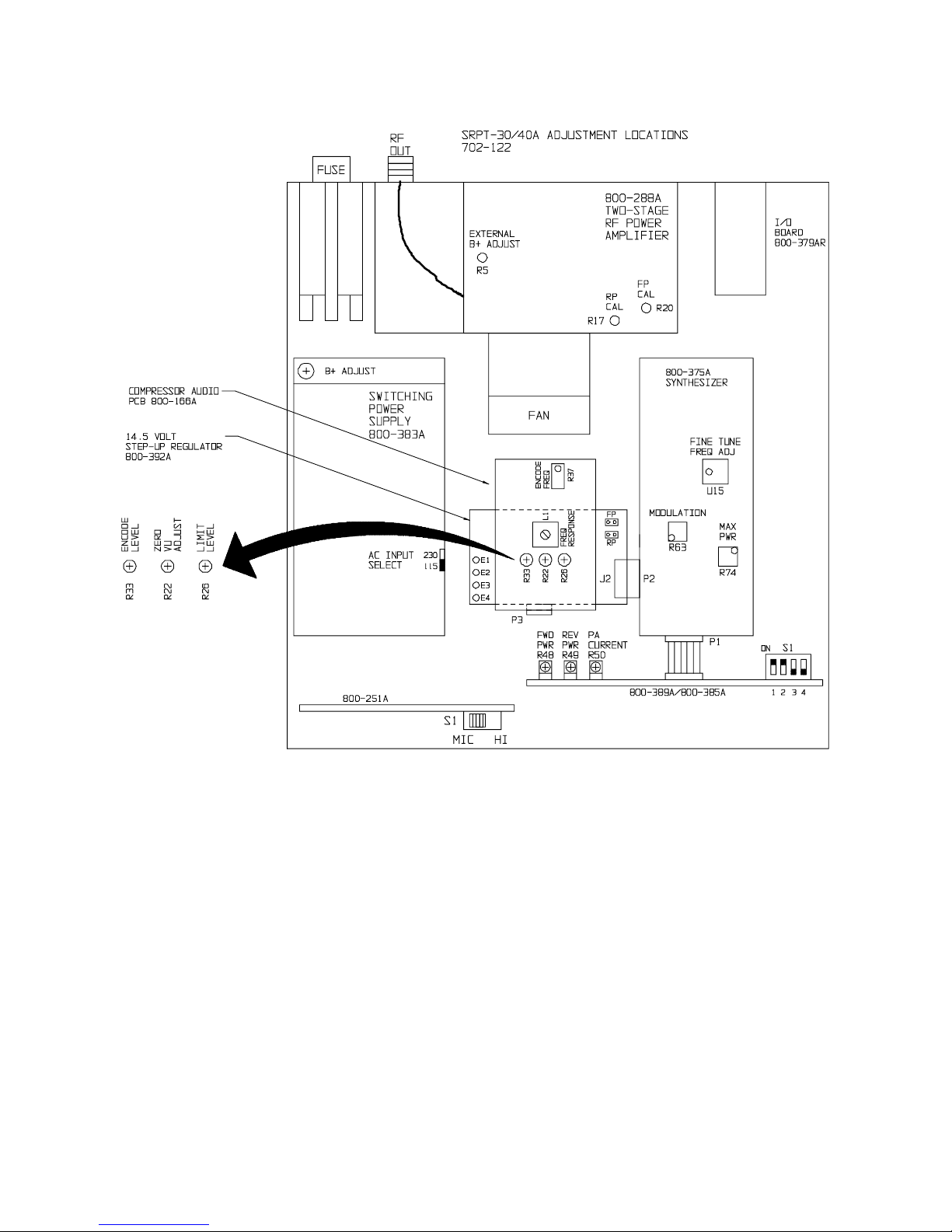
8/7/2003
50
Page 57

SRPT-30/40A
BILL OF MATERIAL
AND
SCHEMATICS
8/7/2003
51
Page 58

P/N SRPT40A-xxx
or SRPT30-xxx
(see legend below for xx(x) and yy)
SYMBOL DESCRIPTION PART NUMBER QTY
Power Cord, Black Detachable Power Dynamics #10088-A 580-116 1
Box, STL-10/R-10/CR-10/RPT-30/SCD-SCG-10 600-041 1
40A only SRPT-40A/xxx 705-ST40A-xx 1
30 only SRPT-30/xxx 705-ST30-xx 1
KIT, BINDER & MANUAL, SRPT-30 979-9967-1 1
SRPT40A (or 30) TX,
xxx MHz
1/10/03
xx(x) = 15(0), 23(0), 25(0), 33(0),
45(0), or 95(0) depending on
model frequency band
yy = 20, 30, 50, or 60
depending on
model MAX power
1
Page 59

P/N 705-ST40A-xx
(see legend below for xx(x) and yy)
SYMBOL DESCRIPTION PART NUMBER QTY
Capacitor, .01 mf 50v GMV disc Jetcon F7Z5U1C103Z-TR 217-104 1
LED INDICATOR,GRN,RECTANGULAR 323-2124 1
IND,LED,RED CMD57124A 323-7124 3
FILTER,RFI,10A 250VAC,50/60HZ 339-0006 1
GROMMET,3/8IDX5/8ODFOR7/16HOLE 400-0014 1
STRIP,QUIET SHIELD,6.00x.197 400-0600 1
GROMMET,FOR 3/8 400-2170 1
ASSY,FEMALE SCREWLOCK 205817-1 420-0817 1
SCREW,2-56X.312,S.S. PH SC 420-2105 2
SCREW,4-40X.312,S.S. PH 420-4105 2
SCREW,4-40X.375,S.S. PH 420-4106 4
SCREW,6-32X.750,S.S. PH 420-6112 2
RIV,1/8X.422L .126-.187GR CLOS 421-1111 8
4-40 KEP NUT 421-4008 2
6-32 KEP NUT 421-6008 4
SOUTHCO SHEET EDGE 6-32 421-6908 4
SCREW,SEMS 6-32 X 7/16" PAN PH.ST. 422-6107 10
#6 LOCK SPLIT 423-6002 2
FILLER,REAR,SRPT-30 471-5385 1
PANEL,BACK,SRPT-30 471-5386 1
PANEL,TOP COVER,SRPT-30 471-5387 1
PANEL,BOTTOM COVER,SRPT-30 471-5388 1
PARTITION,SRPT-30 471-5389 1
Screw, 4-40 x 1/4" phillips pan head M/S Nickel Plated 500-004 14
Screw, 6-32 x 3/8" phillips pan head M/S nickel plated 500-022 2
Lockwasher, #4 internal tooth small pattern zinc plated 500-055 4
Washer, Switchcraft #S1790-1 500-123 1
Flat Washer, Micro Plastics #FW250-062 nylon 500-164 1
Screw, 4-40 x 1/4" phillips pan head M/S Black Zinc 500-180 5
Screw, 6-32 x 1/4" phillips pan head Black Zinc 500-183 28
Screw, 4-40 x 3/8" phillips oval head M/S black zinc 500-188 10
Screw, 6-32 x 3/8" phillips pan head black zinc M/S 500-192 4
Keps nut 4 x 40 zinc 4CNKEOZ 500-199 6
Keps nut 6 x 32 zinc 6CNKEOZ 500-200 2
Screw, SEMS 4-40x1/4 Phillips Pan Head MS Black Zinc 500-210 9
Screw, SEMS 4-40x3/8 Phillips Pan Head MS Black Zinc 500-211 4
Screw,4MM x 5MM Phillips Pan Head MS 500-225 4
Lockwasher,4MM Split 500-226 4
Polytube, Manhatten#AF155A-20-yel 510-005 1
Grommet, 3/8" GC 11-292-C 510-031 4
Fuseholder, Littlefuse #342-004 510-072 1
Bushing, #B-312-250 black shorty Microplastic #22MP01015 510-113 1
Handle Assy., black w/black plated steel hdwe #1879-376-370 510-132 1
Fuse, 4 Amp., 3AG Littlefuse #312-004 510-204 1
Bumper, Bruce Plastics 0772-0014 black 510-205 8
Brackets, #6 Keystone 634 510-210 5
Control Knobs, #45KNO23 510-212 1
SRPT40A/xxx
1/10/03
xx(x) = 15(0), 23(0), 25(0), 33(0),
45(0), or 95(0) depending on
model frequency band
yy = 20, 30, 50, or 60
depending on
model MAX power
1
Page 60

P/N 705-ST40A-xx
(see legend below for xx(x) and yy)
Control Knob, #ME450-2023 510-215 4
Fan, NMB 2410ML04WB40-P00 or ADDA #AD0612HS-A70GL 510-231 1
Flexible Grommet, Tyton FP/A (82' per roll) 510-246 1
Shrink-Tubing, 1/8" B2 Black 510-259 0.1
Spacer, #6 x 1/4 round Keystone 1457A 513-019 2
Spacer, 4-40 x 1/2 hex threaded Keystone 1450C 513-026 2
Spacer, 4-40 x 1/2 hex threaded insulated Keystone 1902C 513-040 4
Switch, slide DPDT Switchcraft 46206LR 530-001 1
Switch, toggle SPDT C&K 7101MYZQ or Apem #5636AB16 530-008 1
Switch, Pushbutton,SPST, Momentary, Green, Mouser#103-1209 530-085 1
Switch,Pushwheel,BCD 10 Position Mouser #106-9905 530-087 7
Switch End Cap, Right Side Mouser#106-9901 530-088 1
Switch End Cap, Left Side Mouser #106-9902 530-089 1
Switch, Rocker, Miniature,DPDT, Red Mouser #629-GRS402210 530-090 1
Connector, Tini-Jax Switchcraft 41 550-083 1
Connector Shell XLR Receptacle 550-155-2 4
Connector pins, Molex 16-02-0086 550-205 4
Connector, 4 Pin Single Row Housing Molex #M0L50-57-9004 550-229 2
Wire, UL1061 22/7 OTC Black 580-040 1
Wire, UL1061 22/7 OTC White/Violet 580-058 0
Wire, UL1061 22/7 OTC Yellow/Violet 580-061 0
Cable Assembly w/2 conn. KSM-2189-05" 586-115 1
Ribbon Cable 6" Digi Key #M3AAA1606R-ND 586-134 1
Cable Assembly, AC Connector to Fuseholder 586-194 1
Cable Assembly, AC Connector to Ground 586-195 1
CABLE ASSEMBLY, SRPT-30/40A MN HRNS(SBCM) 586-211 1
Cover,Two Stage Power Amplifier 700-226-61 1
Front Panel, SRPT-40A 700-250-42 1
SRPT-40A Audio Board 800-166A40A 1
RPT-30/SRPT-40 Pre-Amp Mixer(SBCM) 800-251A 1
TRANSMITTER SYNTHESIZER ASSY xxx Band 800-375ATxxx 1
RPU Transmitter I/O Board Assy (SBCM) 800-379AR 1
Power Supply, Switching 15V, 10 Amp 800-383A 1
SRPT40A/xxx
1/10/03
Uses one of the following Front Panel Control & Meter Boards:
SRPT-40A FRONT PANEL CONTROL & METER 800-385A 1
SRPT-40A FRONT PANEL CONTROL & METER 800-378A 1
Uses one of the following PA assemblies:
PA ASSY, xxx MHZ, yyW 800-388Axxx-yy 1
PA ASSY, xxx MHZ, yyW 800-373Axxx-yy 1
14.5 VOLT STEP-UP REGULATOR 800-392A 1
xx(x) = 15(0), 23(0), 25(0), 33(0),
45(0), or 95(0) depending on
model frequency band
OR
OR
yy = 20, 30, 50, or 60
depending on
model MAX power
2
Page 61

P/N 705-ST40A-xx
(see legend below for xx(x) and yy)
CABLE, RF OUTPUT, SRPT-40A (SBCM) 949-0365 1
Cover Gasket 2/4-CH DSTL Drawing #A1D4040 REV 2 DB65112 0
SRPT40A/xxx
1/10/03
xx(x) = 15(0), 23(0), 25(0), 33(0),
45(0), or 95(0) depending on
model frequency band
yy = 20, 30, 50, or 60
depending on
model MAX power
3
Page 62

P/N 705-ST30-xx
(see legend below for xx(x) and yy)
SYMBOL DESCRIPTION PART NUMBER QTY
Capacitor, .01 mf 50v GMV disc Jetcon F7Z5U1C103Z-TR 217-104 1
LED INDICATOR,GRN,RECTANGULAR 323-2124 1
IND,LED,RED CMD57124A 323-7124 3
FILTER,RFI,10A 250VAC,50/60HZ 339-0006 1
GROMMET,3/8IDX5/8ODFOR7/16HOLE 400-0014 1
STRIP,QUIET SHIELD,6.00x.197 400-0600 1
GROMMET,FOR 3/8 400-2170 1
HSNG,MOD IV 4 POS 87499-7 AMP 417-0138 1
CONTACT,CRIMP,MOD-IV 87809-1 417-8766 4
ASSY,FEMALE SCREWLOCK 205817-1 420-0817 2
SCREW,2-56X.312,S.S. PH SC 420-2105 2
SCREW,M3 X 20,PHILLIPS PAN HEAD,SS 420-3720 4
SCREW,4-40X.312,S.S. PH 420-4105 2
SCREW,4-40X.375,S.S. PH 420-4106 4
SCREW,6-32X.750,S.S. PH 420-6112 2
RIV,1/8X.422L .126-.187GR CLOS 421-1111 8
4-40 X .187 S.S. HEX NUT 421-4007 2
4-40 KEP NUT 421-4008 2
6-32 KEP NUT 421-6008 5
SOUTHCO SHEET EDGE 6-32 421-6908 4
SCREW,SEMS 6-32 X 7/16" PAN PH.ST. 422-6107 18
#4 LOCK S.S. SPLIT 423-4002 6
#6 LOCK SPLIT 423-6002 6
STOFF,ALUM 1/4HEX X 1 1/2 6-32 441-0068 4
FILLER,REAR,SRPT-30 471-5385 1
PANEL,BACK,SRPT-30 471-5386 1
PANEL,TOP COVER,SRPT-30 471-5387 1
PANEL,BOTTOM COVER,SRPT-30 471-5388 1
PARTITION,SRPT-30 471-5389 1
Screw, 4-40 x 1/4" phillips pan head M/S Nickel Plated 500-004 4
Screw, 6-32 x 3/8" phillips pan head M/S nickel plated 500-022 2
Washer, Switchcraft #S1790-1 500-123 1
Flat Washer, Micro Plastics #FW250-062 nylon 500-164 1
Screw, 6-32 x 1/4" phillips pan head Black Zinc 500-183 24
Screw, 4-40 x 3/8" phillips oval head M/S black zinc 500-188 10
Keps nut 4 x 40 zinc 4CNKEOZ 500-199 4
Screw, SEMS 4-40x1/4 Phillips Pan Head MS Black Zinc 500-210 11
Screw, SEMS 4-40x3/8 Phillips Pan Head MS Black Zinc 500-211 4
Polytube, Manhatten#AF155A-20-yel 510-005 0
Grommet, 3/8" GC 11-292-C 510-031 4
Fuseholder, Littlefuse #342-004 510-072 1
Bushing, #B-312-250 black shorty Microplastic #22MP01015 510-113 1
Handle Assy., black w/black plated steel hdwe #1879-376-370 510-132 1
Fuse, 4 Amp., 3AG Littlefuse #312-004 510-204 1
Bumper, Bruce Plastics 0772-0014 black 510-205 8
Brackets, #6 Keystone 634 510-210 5
Control Knobs, #45KNO23 510-212 1
SRPT30/xxx
1/10/03
xx(x) = 15(0), 23(0), 25(0), 33(0),
45(0), or 95(0) depending on
model frequency band
yy = 20, 30, 50, or 60
depending on
model MAX power
1
Page 63

P/N 705-ST30-xx
(see legend below for xx(x) and yy)
Control Knob, #ME450-2023 510-215 4
Fan, NMB 2410ML04WB40-P00 or ADDA #AD0612HS-A70GL 510-231 1
Flexible Grommet, Tyton FP/A (82' per roll) 510-246 1
Shrink-Tubing, 1/8" B2 Black 510-259 0.1
Spacer, 4-40 x 1/2 hex threaded Keystone 1450C 513-026 2
Spacer, 4-40 x 1/2 hex threaded insulated Keystone 1902C 513-040 4
Switch, slide DPDT Switchcraft 46206LR 530-001 1
Switch, toggle SPDT C&K 7101MYZQ or Apem #5636AB16 530-008 2
Switch, Rocker, Miniature,DPDT, Red Mouser #629-GRS402210 530-090 1
Connector, Tini-Jax Switchcraft 41 550-083 1
Connector Shell XLR Receptacle 550-155-2 4
Cable Assembly w/2 conn. KSM-2189-05" 586-115 1
Ribbon Cable 6" Digi Key #M3AAA1606R-ND 586-134 1
Cable Assembly, AC Connector to Fuseholder 586-194 1
Cable Assembly, AC Connector to Ground 586-195 1
CABLE ASSEMBLY, SRPT-30/40A MN HRNS(SBCM) 586-211 1
Cover,Two Stage Power Amplifier 700-226-61 1
FRONT PANEL, SRPT-30 700-250-44 1
SRPT-40A Audio Board 800-166A40A 1
RPT-30/SRPT-40 Pre-Amp Mixer(SBCM) 800-251A 1
TRANSMITTER SYNTHESIZER ASSY xxx Band 800-375ATxxx 1
RPU Transmitter I/O Board Assy (SBCM) 800-379AR 1
Power Supply, Switching 15V, 10 Amp 800-383A 1
SRPT30/xxx
1/10/03
Uses one of the following PA assemblies:
PA ASSY, xxx MHZ, yyW 800-388Axxx-yy 1
OR
PA ASSY, xxx MHZ, yyW 800-373Axxx-yy 1
Uses one of the following Front Panel Control & Meter Boards:
SRPT-30 FP CONTROL & METER BRD ASSY (SBCM) 800-389A 1
OR
SRPT-30 FP CONTROL & METER BRD ASSY (SBCM) 800-382A 1
14.5 VOLT STEP-UP REGULATOR 800-392A 1
CABLE, RF OUTPUT, SRPT-40A (SBCM) 949-0365 1
Cover Gasket 2/4-CH DSTL Drawing #A1D4040 REV 2 DB65112 0
xx(x) = 15(0), 23(0), 25(0), 33(0),
45(0), or 95(0) depending on
model frequency band
yy = 20, 30, 50, or 60
depending on
model MAX power
2
Page 64

P/N 979-9967-1
Kit, Binder-Manual,
SRPT30/40A REV 1
(see legend below for xx(x) and yy)
SYMBOL DESCRIPTION PART NUMBER QTY
INSTRUCTION MANUAL, SRPT30/40A REV1 566-035-1 1
MAN,COVER,MARTI REAR 597-9996 1
MAN,COVER,MARTI FRONT, W/WINDOW 597-9997 1
BINDER,MARTI,1 IN,BLUE,W CD POCKET 598-0013 1
1/10/03
xx(x) = 15(0), 23(0), 25(0), 33(0),
45(0), or 95(0) depending on
model frequency band
yy = 20, 30, 50, or 60
depending on
model MAX power
1
Page 65

P/N 949-0365
Cable, RF Output,
SRPT-40A
(see legend below for xx(x) and yy)
SYMBOL DESCRIPTION PART NUMBER QTY
Connector, UG-58A/U N panel receptacle Amphenol 8297 550-037 1
Connector, UG-177/U UHF hood Amphenol 83-765 550-057 1
CBL,COAX,RG316/U,50 OHM 621-1359 0
10/30/02
xx(x) = 15(0), 23(0), 25(0), 33(0),
45(0), or 95(0) depending on
model frequency band
yy = 20, 30, 50, or 60
depending on
model MAX power
1
Page 66

P/N 586-211
g
p
p
v
Cable Assembly,
SRPT-30/40A Main Harness
(see legend below for xx(x) and yy)
SYMBOL DESCRIPTION PART NUMBER QTY
LUG,QUICK DISCONNECT #18-22 410-1421 3
LUG,TERM #6 SPADE #16-22 410-1489 7
HSNG,MOD IV 4 POS 87499-7 AMP 417-0138 1
CONTACT,CRIMP,MOD-IV 87809-1 417-8766 28
Solder Lug, #6 Concord 707-1406 512-009 2
Terminal,NICHIFU TMDN #125-250-03FA TERMINAL 512-020 5
Connector, 6 pin Molex housing 09-50-8060 550-135 2
Connector, Crimp Terminal Pin Molex 08-52-0112 550-327 39
Wire, UL1061 22/7 OTC Black 580-040 5
Wire, UL1061 22/7 OTC White 580-042 1
Wire, UL1061 22/7 OTC Red 580-043 4
Wire, UL1061 22/7 OTC Yellow 580-044 2
Wire, UL1061 22/7 OTC Green 580-046 1
Wire, UL1061 22/7 OS-1 Orange 580-047 1
Wire, UL1061 22/7 OTC Violet 580-048 1
Wire, UL1061 22/7 OTC Slate 580-049 1
Wire, UL1061 22/7 OS-1 White/Red 580-050 2
Wire, UL1061 22/7 OTC White/Blue 580-051 2
Wire, UL1061 22/7 OTC White/Orange 580-052 1
Wire, UL1061 22/7 OTC White/Brown 580-055 2
Wire, UL1061 22/7 OTC White/Slate 580-056 3
Wire, UL1061 22/7 OTC White/Violet 580-058 2
Wire, UL1061 22/7 OTC Yellow/Blue 580-059 2
Wire, UL1429 22/7 OS-1 Yellow/Green 580-060 2
Wire, UL1061 22/7 OTC Yellow/Brown w/ overall tin coatin
Shielded Wire, 16-C-22-SPJ White/Orange 1 cond 22/19x34
Shielded Wire, 16-C-22-SPJ White/Yellow 1 Cond.22/19x34
Shielded Wire, 16-C-22-SPJ White/Green 1 Cond.22/19x34
Shielded Wire, 16-C-22-SPJ White/Blue 1 Cond.22/19x34 p
Wire, Stranded UL1015-20/10 Black Tinned Copper 580-130 6
Wire, UL1061-18/16 #18 Red #M370-2 580-133 12
Wire, UL1061-18/16 #18 Blue 580-136 1
WIRE,AWG22,19/34 WHT 601-2209 1
J1 Connector, 10 pin Molex housing 09-50-8100 550-122 1
J1,J2 Connector, 8 pin Molex housing 09-50-8080 550-137 2
J2,J3 HOUSING, 16 PIN, DOUBLE ROW, AMP 1-87456-2 417-0602 2
J3 HOUSING,SKT,6PIN,AMP MOD IV 417-0601 1
J6 Connector, 8 pin Molex housing 09-50-8080 550-137 1
580-065 1
580-089 2
580-090 1
580-091 2
580-092 1
10/30/02
xx(x) = 15(0), 23(0), 25(0), 33(0),
45(0), or 95(0) depending on
model frequency band
yy = 20, 30, 50, or 60
depending on
model MAX power
1
Page 67

P/N 586-194
Cable Assembly,
AC Connector to
(see legend below for xx(x) and yy)
SYMBOL DESCRIPTION PART NUMBER QTY
Terminal,NICHIFU TMDN #125-250-03FA TERMINAL 512-020 2
Wire, Stranded UL1015-20/10 Black Tinned Copper 580-130 0
10/30/02
xx(x) = 15(0), 23(0), 25(0), 33(0),
45(0), or 95(0) depending on
model frequency band
yy = 20, 30, 50, or 60
depending on
model MAX power
1
Page 68

P/N 586-195
Cable Assembly,
AC Connector to Ground
(see legend below for xx(x) and yy)
SYMBOL DESCRIPTION PART NUMBER QTY
Solder Lug, #4 short Concord 707-1204 512-018 1
Terminal,NICHIFU TMDN #125-250-03FA TERMINAL 512-020 1
Wire, Stranded UL1015-20/10 Black Tinned Copper 580-130 0
10/30/02
xx(x) = 15(0), 23(0), 25(0), 33(0),
45(0), or 95(0) depending on
model frequency band
yy = 20, 30, 50, or 60
depending on
model MAX power
1
Page 69

P/N 800-392A
14.5 VOLT STEP-UP
1/10/03
REGULATOR
(see legend below for xx(x) and yy)
SYMBOL DESCRIPTION PART NUMBER QTY
Open Top Two Circuit Shunt Molex 15-38-1024 550-182 1
PCB, 14.5 VOLT STEP-UP REGULATOR 800-392B 1
C1 TANTALUM, SMT, D, 100UF, LOW ESR 298-107-1 1
C2 CAPACITOR, SMT, 1206, 6800 PF, 5% 270-682 1
C3 Cap., Tantalum, SMT, Size B, 10uF, 16V,Kemet T491B106K016AS 298-106 1
C4 Cap., monolithic chip, 100 pf 50v 5% Kemet C1206C101J5GAC 270-101 1
C5 TANTALUM, SMT, D, 100UF, LOW ESR 298-107-1 1
C6,C7 Cap,monolithic,1000pf 50v 5%KemetC1206C102J5GACTR marked 270-102 2
C8 Cap SMT 1mF 16V Tantalum Kemet T491A105M016AS 298-105 1
D1 DIODE, SMT, 1A, SCHOTTKY RECTIFIER 418-120 1
E1-E4 TERM,TURRET,2 SHLDR,.219,GOLD FLASH 413-1597 4
J2 RCPT, 20 POS, 2 ROW, R-ANG, PCB 417-2043 1
L1 INDUCTOR, SMT, POWER, 10UH 350-103P 1
L2 Inductor,SMT, 1812, 82nH, Coilcraft 1812SMS-82NJ 350-201 1
P1 Connector, 2 dual pin header (cut from 550-316) 550-191 1
P3 Conn,16-Pin (cut from 550-325) Right Angle 550-325-16 1
P4 Connector,Header 10 Pin RI-10-1 Unsheltered 5x2x1 550-269 1
R1 RESISTOR, SMT, 1206, 110K OHM, 1% 185-110K 1
R2 Resistor, 10K ohm 1/8 watt 1% chip Dale CRCW1206-10K 185-103 1
R3 Resistor, SMT, 1206, 6.81K Ohm, Dale CRCW1206-6.81K 185-6.81K 1
R4 Resistor, SMT, size 1206, 162K ohms, Dale CRCW1206-162K 185-162K 1
R5 Resistor, SMT, 1206, 39.2K ohm 1% Dale CWCR1206-39.2K 185-393 1
R6 Resistor, SMT, size 1206, 392 ohms, Dale CRCW1206-392 185-392 1
R7 Resistor, SMT, size 1206, 2.74K ohms, Dale CRCW1206-2.74K 185-2.74K 1
U1 IC, SMT, 1.5A STEP-UP REGULATOR 400-196 1
U2 IC, SMT, Regulator,Adjustable, 1.5 Amps,National LM317AEMP 401-317 1
xx(x) = 15(0), 23(0), 25(0), 33(0),
45(0), or 95(0) depending on
model frequency band
yy = 20, 30, 50, or 60
depending on
model MAX power
1
Page 70

P/N 800-251A
RPT-30/SRPT-40
10/30/02
Pre-Amp Mixer
(see legend below for xx(x) and yy)
SYMBOL DESCRIPTION PART NUMBER QTY
Grounding Strap, RPT-30 Pre-Amp 700-250-15 1
PC Board, Pre-amp/Mixer RPT-30 REV-9520 800-251B 1
Loctite TAK PAK High Temp. Gel #49904 3gm tube 900-018 0
C1,C2 Cap,monolithic,1000pf 50v 5%KemetC1206C102J5GACTR marked 270-102 2
C3,C4 Capacitor. electrolytic 22uF 25V Mepco 3073BA220T025JPA 219-200 2
C5,C6 Capacitor, monolithic chip 27 pf 50v 5% Kemet C1206C270J5GAC 270-270 2
C7 Capacitor, 10 pf 5% NPO disc Pace F5NPO1C1OOJ-TR 255-100 1
C8 Capacitor. electrolytic 22uF 25V Mepco 3073BA220T025JPA 219-200 1
C9,C10 Cap,monolithic,1000pf 50v 5%KemetC1206C102J5GACTR marked 270-102 2
C11,C12 Capacitor. electrolytic 22uF 25V Mepco 3073BA220T025JPA 219-200 2
C13,C14 Capacitor, monolithic chip 27 pf 50v 5% Kemet C1206C270J5GAC 270-270 2
C15 Capacitor, 10 pf 5% NPO disc Pace F5NPO1C1OOJ-TR 255-100 1
C16 Capacitor. electrolytic 22uF 25V Mepco 3073BA220T025JPA 219-200 1
C17,C18 Cap,monolithic,1000pf 50v 5%KemetC1206C102J5GACTR marked 270-102 2
C19,C20 Capacitor. electrolytic 22uF 25V Mepco 3073BA220T025JPA 219-200 2
C21,C22 Capacitor, monolithic chip 27 pf 50v 5% Kemet C1206C270J5GAC 270-270 2
C23 Capacitor, 10 pf 5% NPO disc Pace F5NPO1C1OOJ-TR 255-100 1
C24 Capacitor. electrolytic 22uF 25V Mepco 3073BA220T025JPA 219-200 1
C25,C26 Cap,monolithic,1000pf 50v 5%KemetC1206C102J5GACTR marked 270-102 2
C27,C28 Capacitor. electrolytic 22uF 25V Mepco 3073BA220T025JPA 219-200 2
C29,C30 Capacitor, monolithic chip 27 pf 50v 5% Kemet C1206C270J5GAC 270-270 2
C31 Capacitor, 10 pf 5% NPO disc Pace F5NPO1C1OOJ-TR 255-100 1
C32,C33 Capacitor. electrolytic 22uF 25V Mepco 3073BA220T025JPA 219-200 2
C34-C37 Cap,monolithic,1000pf 50v 5%KemetC1206C102J5GACTR marked 270-102 4
IC1,IC2 Integrated Circuit, Signetics NE5532AN, Phillips 405-532 2
J1-J4 Connector, XLR Receptacle Insert Nuetrik#3FD-V-I-O 550-155-1 4
P1 Connector, 6 pin Molex angle header (cut from 550-163) 550-149 1
R1 Resistor, 2.21K ohm 1/4 watt 1% metal film Mepco SFR25 145-222 1
R2,R3 Resistor, 1.5k ohm 1/4 ohm 1% metal film Mepco SFR25 145-152 2
R4,R5 Resistor, 100k ohm 1/4 watt 1% metal film Mepco SFR25 145-104 2
R6 Resistor, 15k ohm 1/4 watt 1% metal film Mepco SFR25 145-153 1
R7 Potentiometer,25kohm linear taper PC mt Xicon/Alpha #31VQ403 100-143 1
R8 Resistor, 2.21K ohm 1/4 watt 1% metal film Mepco SFR25 145-222 1
R9,R10 Resistor, 1.5k ohm 1/4 ohm 1% metal film Mepco SFR25 145-152 2
R11,R12 Resistor, 100k ohm 1/4 watt 1% metal film Mepco SFR25 145-104 2
R13 Resistor, 15k ohm 1/4 watt 1% metal film Mepco SFR25 145-153 1
R14 Potentiometer,25kohm linear taper PC mt Xicon/Alpha #31VQ403 100-143 1
R15 Resistor, 2.21K ohm 1/4 watt 1% metal film Mepco SFR25 145-222 1
R16,R17 Resistor, 1.5k ohm 1/4 ohm 1% metal film Mepco SFR25 145-152 2
R18,R19 Resistor, 100k ohm 1/4 watt 1% metal film Mepco SFR25 145-104 2
R20 Resistor, 15k ohm 1/4 watt 1% metal film Mepco SFR25 145-153 1
R21 Potentiometer,25kohm linear taper PC mt Xicon/Alpha #31VQ403 100-143 1
R22 Resistor, 2.21K ohm 1/4 watt 1% metal film Mepco SFR25 145-222 1
R23,R24 Resistor, 360k ohm 1/4 watt 1% carbon film CF1/4-360K 145-364-1 2
R25,R26 Resistor, 1.5k ohm 1/4 ohm 1% metal film Mepco SFR25 145-152 2
R27,R28 Resistor, 100k ohm 1/4 watt 1% metal film Mepco SFR25 145-104 2
R29 Resistor, 15k ohm 1/4 watt 1% metal film Mepco SFR25 145-153 1
xx(x) = 15(0), 23(0), 25(0), 33(0),
45(0), or 95(0) depending on
model frequency band
yy = 20, 30, 50, or 60
depending on
model MAX power
1
Page 71

P/N 800-251A
RPT-30/SRPT-40
10/30/02
Pre-Amp Mixer
(see legend below for xx(x) and yy)
R30 Potentiometer,25kohm linear taper PC mt Xicon/Alpha #31VQ403 100-143 1
R31,R32 Resistor, 22.1k ohm 1/4 watt 1% metal film Mepco SFR25 145-223 2
R33 Resistor, 5.6k ohm 1/4 watt 5% metal film Mepco SFR25 145-562 1
S1 Switch, side action slide DPDT Ark-Les S-9022CD00-H 530-051 1
xx(x) = 15(0), 23(0), 25(0), 33(0),
45(0), or 95(0) depending on
model frequency band
yy = 20, 30, 50, or 60
depending on
model MAX power
2
Page 72

P/N 800-166A40A
(see legend below for xx(x) and yy)
SYMBOL DESCRIPTION PART NUMBER QTY
Generic RPU Audio Board Assembly (SBCM) 800-166CM 1
C23 Capacitor, .0024 mfd 2.5% 100v polypro Seacor PFAB240HGUE 215-242 1
R43 Resistor, 1k ohm 1/4 watt 1% metal film Mepco SFR55 1K 1%TR 145-102 1
R46 Resistor, 15k ohm 1/4 watt 1% metal film Mepco SFR25 145-153 1
R48 Resistor, 4.75K ohm 1/4 watt 1% metal film Mepco SFR25 145-472 1
R49 Resistor, 2.21 meg ohm 1/4 watt 1% metal film (2.21 Meg 1%) 145-225 1
SRPT40A Audio Board
5/2/03
xx(x) = 15(0), 23(0), 25(0), 33(0),
45(0), or 95(0) depending on
model frequency band
yy = 20, 30, 50, or 60
depending on
model MAX power
1
Page 73

P/N 800-166CM
Generic RPU Audio
10/30/02
Board Assembly
(see legend below for xx(x) and yy)
SYMBOL DESCRIPTION PART NUMBER QTY
PC Board, Audio RPT-2/15/30 REV-9526 800-166B 1
C1 Capacitor, 470 pf 50v 10% Y5P disc Jetcon F6Y5P1C471K-JT 253-471 1
C2 Capacitor, tantalum, 4.7 mf 16v Kemet T350B475K016AS 299-470 1
C3 Capacitor, 106 50V Radial Electrolytic SPG 515D106M050JA6A 219-106 1
C4 Capacitor, electrolytic 22uF radial 35V 219-220 1
C7 Cap.,.27 mf 100v 10% polypro CD MTC1P27K OR Bishop C21B274K 226-274 1
C9 Capacitor, electrolytic 220uF 25V radial NIC UVX1E221MPA1TD 219-221 1
C10 Cap., 68pF 5% 200V ceramic dipped Kemet C317C680J2G5CA 256-680C 1
C11 Capacitor, .0082 Mfd 2.5% 100v polypro Seacor PFWAB82OHGNE 215-822 1
C12 Capacitor, .01 mf 50v GMV disc Jetcon F7Z5U1C103Z-TR 217-104 1
C13,C14 Capacitor, electrolytic 220uF 25V radial NIC UVX1E221MPA1TD 219-221 2
C15 Capacitor, 470 pf 50v 10% Y5P disc Jetcon F6Y5P1C471K-JT 253-471 1
C16 Capacitor, .1 mf 100v 10% mylar Ohsung OSG2A104K BULK 217-103 1
C17 Capacitor, tantalum, 4.7 mf 16v Kemet T350B475K016AS 299-470 1
C18 Capacitor, 106 50V Radial Electrolytic SPG 515D106M050JA6A 219-106 1
C19 Capacitor, tantalum, 4.7 mf 16v Kemet T350B475K016AS 299-470 1
C20 Capacitor, .012 mfd 2.5% 100v polypro Seacor PFWAC120HGUE 215-123 1
C21 Capacitor, electrolytic 22uF radial 35V 219-220 1
C22 Capacitor, .012 mfd 2.5% 100v polypro Seacor PFWAC120HGUE 215-123 1
C24 Cap., 47pF 5% 200V ceramic dipped Kemet C317C470J2G5CA 255-470C 1
C25 Capacitor, .022 mfd 2.5% 100v polypro Seacor PFWAC220HGNE 215-223 1
C26 Capacitor, .0039 mfd 2.5% polypro Seacor PFWAB390HGNE 215-392 1
C27 Cap., 47pF 5% 200V ceramic dipped Kemet C317C470J2G5CA 255-470C 1
C28 Capacitor, .01 mf 50v GMV disc Jetcon F7Z5U1C103Z-TR 217-104 1
C29 Capacitor, 470 pf 50v 10% Y5P disc Jetcon F6Y5P1C471K-JT 253-471 1
C30 Capacitor, electrolytic 22uF radial 35V 219-220 1
C31 Cap.,.27 mf 100v 10% polypro CD MTC1P27K OR Bishop C21B274K 226-274 1
C32-C41 Cap,monolithic,1000pf 50v 5%KemetC1206C102J5GACTR marked 270-102 10
D1-D5 Diode, 1N4148 Philips 410-914 5
D6 Diode, General Instruments 1N4007 414-007 1
IC1 Integrated Circuit, SGS TDA1054M 401-054 1
IC2 Integrated Circuit, TI LM3900N 403-900 1
L1 Inductor, 387-150M 40000-150000 uH Aurora #47271-011 350-032 1
P1 Connector, 10 pin header (cut from 550-162) 550-123 1
R1 Resistor, 1k ohm 1/4 watt 1% metal film Mepco SFR55 1K 1%TR 145-102 1
R2 Resistor, 47k ohm 1/4 watt 1% metal film Mepco SFR25 145-473 1
R3 Resistor, 182 ohm 1/4 watt 1% metal film Mepco SFR25 145-181 1
R4 Resistor, 680 ohm 1/4 watt 1% metal film Mepco SFR25 145-681 1
R5 Resistor, 150 ohm 1/4 watt 1% metal film Mepco SFR25 145-151 1
R6 Resistor, 100k ohm 1/4 watt 1% metal film Mepco SFR25 145-104 1
R7 Resistor, 3.32k ohm 1/4 watt 1% metal film Mepco SFR55 145-332 1
R8 Resistor, 3.92k ohm 1/4 watt 1% metal film Mepco SFR25 145-392 1
R9 Resistor, 3.3 ohm 1/4 watt 1% metal film Mepco SFR25 145-030 1
R10 Resistor, 3.92k ohm 1/4 watt 1% metal film Mepco SFR25 145-392 1
R11,R12 Resistor, 100k ohm 1/4 watt 1% metal film Mepco SFR25 145-104 2
R13 Resistor, 332 ohm 1/4 watt 1% metal film Mepco SFR25 145-331 1
R14 Resistor, 8.25k ohm 1/4 watt 1% metal film Mepco SFR25 145-822 1
xx(x) = 15(0), 23(0), 25(0), 33(0),
45(0), or 95(0) depending on
model frequency band
yy = 20, 30, 50, or 60
depending on
model MAX power
1
Page 74

P/N 800-166CM
Generic RPU Audio
10/30/02
Board Assembly
(see legend below for xx(x) and yy)
R15 Resistor, 3.92k ohm 1/4 watt 1% metal film Mepco SFR25 145-392 1
R16 Resistor, 33.2k ohm 1/4 watt 1% metal film Mepco SFR25 145-333 1
R17 Resistor, 220 ohm 1/4 watt 1% metal film Mepco SFR25 145-221 1
R19 Resistor, 2.21 meg ohm 1/4 watt 1% metal film (2.21 Meg 1%) 145-225 1
R20 Resistor, 475k ohm 1/4 watt 1% metal film Koa MF55D TR 145-474 1
R22 Potentiometer, 5k ohm cermet Bourns 3309P-1-502 101-502 1
R23 Resistor, 3.32k ohm 1/4 watt 1% metal film Mepco SFR55 145-332 1
R24 Resistor, 2.74K ohm 1/4 watt 1% metal film Mepco SFR25 145-272 1
R25 Resistor, 4.75K ohm 1/4 watt 1% metal film Mepco SFR25 145-472 1
R26 Potentiometer, 100K ohm cermet Bourns 3309P-1-104 101-104 1
R27 Resistor, 2.21K ohm 1/4 watt 1% metal film Mepco SFR25 145-222 1
R28 Resistor, 2.21 meg ohm 1/4 watt 1% metal film (2.21 Meg 1%) 145-225 1
R29 Resistor, 10 meg ohm 1/4 watt 5% metal film Mepco SFR25 145-106 1
R30 Resistor, 8.2 meg ohm 1/4 watt 5% carbon film 29SJ250 145-825 1
R31 Resistor, 221k ohm 1/4 watt 1% RN55D2213F 145-224-1 1
R32 Resistor, 22.1k ohm 1/4 watt 1% metal film Mepco SFR25 145-223 1
R33 Potentiometer, 100K ohm cermet Bourns 3309P-1-104 101-104 1
R34 Resistor, 10k ohm 1/4 watt 1% metal film Mepco SFR25 145-103 1
R35,R36 Resistor, 475k ohm 1/4 watt 1% SFR55 475K 1% 145-474-1 2
R37 Potentiometer, 1meg ohm cermet Bourns 3296Y-1-105 top adjust 104-105 1
R38,R39 Resistor, 1 meg ohm 1/4 watt 1% metal film Mepco SFR25 145-105 2
R40 Resistor, 2.21 meg ohm 1/4 watt 1% metal film (2.21 Meg 1%) 145-225 1
R41 Resistor, 562 ohm 1/4 watt 1% metal film Mepco SFR25 145-561 1
R42 Resistor, 2.21 meg ohm 1/4 watt 1% metal film (2.21 Meg 1%) 145-225 1
R44 Resistor, 8.25k ohm 1/4 watt 1% metal film Mepco SFR25 145-822 1
R45 Resistor, 2.74K ohm 1/4 watt 1% metal film Mepco SFR25 145-272 1
R47 Resistor, 100k ohm 1/4 watt 1% metal film Mepco SFR25 145-104 1
xx(x) = 15(0), 23(0), 25(0), 33(0),
45(0), or 95(0) depending on
model frequency band
yy = 20, 30, 50, or 60
depending on
model MAX power
2
Page 75

P/N 800-385A
SRPT40A Front Panel
10/30/02
Control & Meter Board
(see legend below for xx(x) and yy)
SYMBOL DESCRIPTION PART NUMBER QTY
PC BOARD, FRONT PANEL CONTROL AND METER, SRPT-40A 800-385B 1
B1,B2 Subminiature Lamp, Lumex IFL-LX2162-16T 510-196 2
C1,C2 Cap SMT 1mF 16V Tantalum Kemet T491A105M016AS 298-105 2
C3 Cap,monolithic,1000pf 50v 5%KemetC1206C102J5GACTR marked 270-102 1
C4 Cap, Monolithic chip 10000pF 10% XR7 Kemet C1206C103J5RACTR 270-103 1
C5,C6 Cap SMT 1mF 16V Tantalum Kemet T491A105M016AS 298-105 2
J7,J8 CONN,HEADER 3 PIN 417-0003 2
M1 METER, 60 WATTS, VOLTS/AMPS, VU 030-046M 1
P1 CONN,HEADER,16-PIN,PCB MOUNT 417-1606 1
P2 Connector, 4 pin single header (cut from 550-214) 550-226 1
P4 CONN,HEADER,16-PIN,PCB MOUNT 417-1606 1
P5 Connector, 6 pin Molex header (cut from 550-162) 550-136 1
P5 Connector, 8 pin Molex header (cut from 550-162) 550-138 1
P7,P8 Open Top Two Circuit Shunt Molex 15-38-1024 550-182 2
Q1-Q4 Transistor, SMT, General Purpose,NPN, Motorola MMBT3904LT1 439-041 4
Q5 Transistor, SMT, Darlington, NPN, Mototrola MMBTA14LT1 420-141 1
R1-R14 Resistor, SMT, 1206, 4.75K, Dale CRCW1206-4.75K 185-4.75K 14
R15 Resistor, SMT, 1206, 4.75K, Dale CRCW1206-4.75K 185-4.75K 1
R16-R26 Resistor, SMT, 1206, 4.75K, Dale CRCW1206-4.75K 185-4.75K 11
R27 Resistor, SMT, 1206, 4.75K, Dale CRCW1206-4.75K 185-4.75K 1
R28-R32 Resistor, SMT, 1206, 4.75K, Dale CRCW1206-4.75K 185-4.75K 5
R33 Resistor, 1K ohm 1/8 watt 1% chip Dale CRCW1206-1K 185-102 1
R34-R37 Resistor, SMT, Size 1206, 475 ohms, Dale CRCW1206-475 185-475 4
R38-R41 Resistor, SMT, size 1206, 182 ohms, Dale CRCW1206-182 185-182 4
R42,R43 Resistor, SMT, size 1206, 68.1 ohms, Dale CRCW1206-68.1 185-68.1 2
R44 Resistor, SMT, size 1206, 392 ohms, Dale CRCW1206-392 185-392 1
R45 Resistor, SMT, size 1206, 1.21K ohms, Dale CRCW1206-1.21K 185-1.21K 1
R46 Resistor, SMT, size 1206, 432 ohms, Dale CRCW1206-432 185-432 1
R47 Resistor, SMT, size 1206, 47.5K ohms, Dale CRCW1206-47.5K 185-47.5K 1
R48-R50 Potentiometer, 5k ohm cermet Bourns 3309W-1-502 103-502 3
R51 Potentiometer, 5k ohm cermet Bourns 3309P-1-502 101-502 1
R52,R53 Resistor, SMT, size 1206, 68.1 ohms, Dale CRCW1206-68.1 185-68.1 2
R54-R57 Resistor, 1K ohm 1/8 watt 1% chip Dale CRCW1206-1K 185-102 4
R58,R59 Resistor, 10K ohm 1/8 watt 1% chip Dale CRCW1206-10K 185-103 2
R60 Resistor, 1K ohm 1/8 watt 1% chip Dale CRCW1206-1K 185-102 1
R61 RESISTOR, 332 OHM, SURFACE MOUNT,+/-1%, 1/8W 185-332 1
S1 Switch, Dip, 4 Position, Right Angle, Apem DA04T 530-086 1
S2 Switch, rotary 10WA135 530-059 1
U1-U4 IC, 8-Bit Ser/Par In, Ser Out SR Phillips 74HC165D 401-165 4
U5 IC, SMT, 8-Bit Ser In, Par Out SR Phillips 74HC164D 401-164 1
U6 IC, Octal D Flip-Flop w 3-St Out Phillips 74HC374D 401-374 1
U7 IC, SMT, Regulator,Adjustable, 1.5 Amps,National LM317AEMP 401-317 1
U8-U11 IC, Inverter, Open-drain Gate 400-106 4
U12 ICSMT, Digital Pot,2 Ch,100K ohms,Analog Device AD8402AR100 408-402 1
U13 IC,OP-amp, General Purpose Analog Device OP295GS 400-295 1
xx(x) = 15(0), 23(0), 25(0), 33(0),
45(0), or 95(0) depending on
model frequency band
yy = 20, 30, 50, or 60
depending on
model MAX power
1
Page 76

P/N 800-378A
SRPT40A Front Panel
10/30/02
Control & Meter Board
(see legend below for xx(x) and yy)
SYMBOL DESCRIPTION PART NUMBER QTY
PC Board, Front Panel Control and Meter (NLU-02) 800-378B 1
B1,B2 Subminiature Lamp, Lumex IFL-LX2162-16T 510-196 2
C1,C2 Cap SMT 1mF 16V Tantalum Kemet T491A105M016AS 298-105 2
C3 Cap,monolithic,1000pf 50v 5%KemetC1206C102J5GACTR marked 270-102 1
C4 Cap, Monolithic chip 10000pF 10% XR7 Kemet C1206C103J5RACTR 270-103 1
M1 Meter, Watts, Volts/Amps,VU 030-045M 1
P1 Connector, Dual Row Header, 40-Pin (cut from 550-326) 550-326-40 1
P2,P3 Connector, 4 pin single header (cut from 550-214) 550-226 2
P4 Connector, Dual Row Header, 16-Pin (cut from 550-326) 550-326-16 1
P5 Connector, 6 pin Molex header (cut from 550-162) 550-136 1
P5 Connector, 8 pin Molex header (cut from 550-162) 550-138 1
Q1-Q4 Transistor, SMT, General Purpose,NPN, Motorola MMBT3904LT1 439-041 4
R1-R14 Resistor, SMT, 1206, 4.75K, Dale CRCW1206-4.75K 185-4.75K 14
R15 Resistor, SMT, 1206, 4.75K, Dale CRCW1206-4.75K 185-4.75K 1
R16-R26 Resistor, SMT, 1206, 4.75K, Dale CRCW1206-4.75K 185-4.75K 11
R27 Resistor, SMT, 1206, 4.75K, Dale CRCW1206-4.75K 185-4.75K 1
R28-R32 Resistor, SMT, 1206, 4.75K, Dale CRCW1206-4.75K 185-4.75K 5
R33 Resistor, 1K ohm 1/8 watt 1% chip Dale CRCW1206-1K 185-102 1
R34-R37 Resistor, SMT, Size 1206, 475 ohms, Dale CRCW1206-475 185-475 4
R38-R41 Resistor, SMT, size 1206, 182 ohms, Dale CRCW1206-182 185-182 4
R42,R43 Resistor, SMT, size 1206, 68.1 ohms, Dale CRCW1206-68.1 185-68.1 2
R44 Resistor, SMT, size 1206, 392 ohms, Dale CRCW1206-392 185-392 1
R45 Resistor, SMT, size 1206, 1.21K ohms, Dale CRCW1206-1.21K 185-1.21K 1
R46 Resistor, SMT, size 1206, 432 ohms, Dale CRCW1206-432 185-432 1
R47 Resistor, SMT, size 1206, 47.5K ohms, Dale CRCW1206-47.5K 185-47.5K 1
R48-R50 Potentiometer, 5k ohm cermet Bourns 3309W-1-502 103-502 3
R51 Potentiometer, 5k ohm cermet Bourns 3309P-1-502 101-502 1
R52,R53 Resistor, SMT, size 1206, 68.1 ohms, Dale CRCW1206-68.1 185-68.1 2
S1 Switch, Dip, 4 Position, Right Angle, Apem DA04T 530-086 1
S2 Switch, rotary 10WA135 530-059 1
U1-U4 IC, 8-Bit Ser/Par In, Ser Out SR Phillips 74HC165D 401-165 4
U5 IC, SMT, 8-Bit Ser In, Par Out SR Phillips 74HC164D 401-164 1
U6 IC, Octal D Flip-Flop w 3-St Out Phillips 74HC374D 401-374 1
U7 IC, SMT, Regulator,Adjustable, 1.5 Amps,National LM317AEMP 401-317 1
xx(x) = 15(0), 23(0), 25(0), 33(0),
45(0), or 95(0) depending on
model frequency band
yy = 20, 30, 50, or 60
depending on
model MAX power
1
Page 77

P/N 800-389A
SRPT30 Front Panel
10/30/02
Control & Meter Board
(see legend below for xx(x) and yy)
SYMBOL DESCRIPTION PART NUMBER QTY
SRPT-30 FP CONTROL & METER BRD 800-389B 1
B1,B2 Subminiature Lamp, Lumex IFL-LX2162-16T 510-196 2
C1,C2 Cap SMT 1mF 16V Tantalum Kemet T491A105M016AS 298-105 2
C3 Cap,monolithic,1000pf 50v 5%KemetC1206C102J5GACTR marked 270-102 1
C4 Cap, Monolithic chip 10000pF 10% XR7 Kemet C1206C103J5RACTR 270-103 1
C5,C6 Cap SMT 1mF 16V Tantalum Kemet T491A105M016AS 298-105 2
J7,J8 CONN,HEADER 3 PIN 417-0003 2
M1 METER, 60 WATTS, VOLTS/AMPS, VU 030-046M 1
P1 CONN,HEADER,16-PIN,PCB MOUNT 417-1606 1
P2 Connector, 4 pin single header (cut from 550-214) 550-226 1
P4 CONN,HEADER,16-PIN,PCB MOUNT 417-1606 1
P5 Connector, 6 pin Molex header (cut from 550-162) 550-136 1
P5 Connector, 8 pin Molex header (cut from 550-162) 550-138 1
P7,P8 Open Top Two Circuit Shunt Molex 15-38-1024 550-182 2
Q1-Q4 Transistor, SMT, General Purpose,NPN, Motorola MMBT3904LT1 439-041 4
Q5 Transistor, SMT, Darlington, NPN, Mototrola MMBTA14LT1 420-141 1
R34-R37 Resistor, SMT, Size 1206, 475 ohms, Dale CRCW1206-475 185-475 4
R38-R41 Resistor, SMT, size 1206, 182 ohms, Dale CRCW1206-182 185-182 4
R42,R43 Resistor, SMT, size 1206, 68.1 ohms, Dale CRCW1206-68.1 185-68.1 2
R44 Resistor, SMT, size 1206, 392 ohms, Dale CRCW1206-392 185-392 1
R45 Resistor, SMT, size 1206, 1.21K ohms, Dale CRCW1206-1.21K 185-1.21K 1
R46 Resistor, SMT, size 1206, 432 ohms, Dale CRCW1206-432 185-432 1
R47 Resistor, SMT, size 1206, 47.5K ohms, Dale CRCW1206-47.5K 185-47.5K 1
R48-R50 Potentiometer, 5k ohm cermet Bourns 3309W-1-502 103-502 3
R51 Potentiometer, 5k ohm cermet Bourns 3309P-1-502 101-502 1
R52,R53 Resistor, SMT, size 1206, 68.1 ohms, Dale CRCW1206-68.1 185-68.1 2
R55 Resistor, 1K ohm 1/8 watt 1% chip Dale CRCW1206-1K 185-102 1
R58,R59 Resistor, 10K ohm 1/8 watt 1% chip Dale CRCW1206-10K 185-103 2
R60 Resistor, 1K ohm 1/8 watt 1% chip Dale CRCW1206-1K 185-102 1
R61 RESISTOR, 332 OHM, SURFACE MOUNT,+/-1%, 1/8W 185-332 1
S2 Switch, rotary 10WA135 530-059 1
U5 IC, SMT, 8-Bit Ser In, Par Out SR Phillips 74HC164D 401-164 1
U6 IC, Octal D Flip-Flop w 3-St Out Phillips 74HC374D 401-374 1
U7 IC, SMT, Regulator,Adjustable, 1.5 Amps,National LM317AEMP 401-317 1
U12 ICSMT, Digital Pot,2 Ch,100K ohms,Analog Device AD8402AR100 408-402 1
U13 IC,OP-amp, General Purpose Analog Device OP295GS 400-295 1
xx(x) = 15(0), 23(0), 25(0), 33(0),
45(0), or 95(0) depending on
model frequency band
yy = 20, 30, 50, or 60
depending on
model MAX power
1
Page 78

P/N 800-382A
SRPT30 Front Panel
10/30/02
Control & Meter Board
(see legend below for xx(x) and yy)
SYMBOL DESCRIPTION PART NUMBER QTY
ISOLATOR,ADH BACKED,.063 X .75 400-0055 3
FLAT .750 X .312 X .030 423-3008 3
PC BOARD, FP CNTL AND MTR, SRPT-30 800-382B 1
B1,B2 Subminiature Lamp, Lumex IFL-LX2162-16T 510-196 2
C1,C2 Cap SMT 1mF 16V Tantalum Kemet T491A105M016AS 298-105 2
C3 Cap,monolithic,1000pf 50v 5%KemetC1206C102J5GACTR marked 270-102 1
C4 Cap, Monolithic chip 10000pF 10% XR7 Kemet C1206C103J5RACTR 270-103 1
M1 Meter, Watts, Volts/Amps,VU 030-045M 1
P1 CONN,HEADER,16-PIN,PCB MOUNT 417-1606 1
P2 Connector, 4 pin single header (cut from 550-214) 550-226 1
P4 CONN,HEADER,16-PIN,PCB MOUNT 417-1606 1
P5 Connector, 6 pin Molex header (cut from 550-162) 550-136 1
P6 Connector, 8 pin Molex header (cut from 550-162) 550-138 1
Q1-Q4 Transistor, SMT, General Purpose,NPN, Motorola MMBT3904LT1 439-041 4
R34-R37 Resistor, SMT, Size 1206, 475 ohms, Dale CRCW1206-475 185-475 4
R38-R41 Resistor, SMT, size 1206, 182 ohms, Dale CRCW1206-182 185-182 4
R42,R43 Resistor, SMT, size 1206, 68.1 ohms, Dale CRCW1206-68.1 185-68.1 2
R44 Resistor, SMT, size 1206, 392 ohms, Dale CRCW1206-392 185-392 1
R45 Resistor, SMT, size 1206, 1.21K ohms, Dale CRCW1206-1.21K 185-1.21K 1
R46 Resistor, SMT, size 1206, 432 ohms, Dale CRCW1206-432 185-432 1
R47 Resistor, SMT, size 1206, 47.5K ohms, Dale CRCW1206-47.5K 185-47.5K 1
R48-R50 Potentiometer, 5k ohm cermet Bourns 3309W-1-502 103-502 3
R51 Potentiometer, 5k ohm cermet Bourns 3309P-1-502 101-502 1
R52,R53 Resistor, SMT, size 1206, 68.1 ohms, Dale CRCW1206-68.1 185-68.1 2
R55 Resistor, 1K ohm 1/8 watt 1% chip Dale CRCW1206-1K 185-102 1
S2 Switch, rotary 10WA135 530-059 1
U5 IC, SMT, 8-Bit Ser In, Par Out SR Phillips 74HC164D 401-164 1
U6 IC, Octal D Flip-Flop w 3-St Out Phillips 74HC374D 401-374 1
U7 IC, SMT, Regulator,Adjustable, 1.5 Amps,National LM317AEMP 401-317 1
xx(x) = 15(0), 23(0), 25(0), 33(0),
45(0), or 95(0) depending on
model frequency band
yy = 20, 30, 50, or 60
depending on
model MAX power
1
Page 79

P/N 800-379AR
RPU Transmitter
10/30/02
I/O Board Assy (SBCM)
(see legend below for xx(x) and yy)
SYMBOL DESCRIPTION PART NUMBER QTY
Screw, 4-40 x 7/16" phillips pan head MS zinc plated 500-162 2
PC Board, STL/RPU Transmitter I/O Rev A 800-379B 1
C1-C6 Cap,monolithic,1000pf 50v 5%KemetC1206C102J5GACTR marked 270-102 6
C7-C9 Cap, monolithic chip, 22 pf 50v 5% KEMET C1206C220J5GACTR 270-220 3
J4 Connector, D-Sub 15 pin angle Keltron DNR-15PJL-SG 550-170 1
L1,L2 Inductor, SMT, Power, 0.68, Coilcraft DO3316P-681HC 350-196 2
L3-L9 Inductor, 10uH SMT DN12103JTR-ND DELEVAN 5% 330-024 7
P2 Connector, 8 pin Molex angle header (cut from 550-163) 550-176 1
P3 Conn,2x8 pin dual row header right angle cut from 550-217 550-211 1
xx(x) = 15(0), 23(0), 25(0), 33(0),
45(0), or 95(0) depending on
model frequency band
yy = 20, 30, 50, or 60
depending on
model MAX power
1
Page 80

P/N 800-375ATxxx
Transmitter Synthesizer
Assembly xxx
(see legend below for xx(x) and yy)
SYMBOL DESCRIPTION PART NUMBER QTY
Transmitter Synthesizer Board Assy Generic (SBCM) 800-375AT 1
RPU/STL XMIT SYN SW VERSION 2 800-375ATSW2 1
150 MHz Band Model
U6 IC, VCO, 135-185 MHz 400-185 1
230 and 250 MHz Band Models
U6 IC, VCO, 215-265 MHz 400-265 1
330 MHz Band Model
U6 IC, VCO, 300-350 MHz 400-351 1
450 MHz Band Model
U6 IC, VCO, 430-480 MHz 400-480 1
950 MHz Band Model
U6 IC, VCO, 935-965 MHz 400-965 1
10/30/02
xx(x) = 15(0), 23(0), 25(0), 33(0),
45(0), or 95(0) depending on
model frequency band
yy = 20, 30, 50, or 60
depending on
model MAX power
1
Page 81

P/N 800-375AT
Transmitter Synthesizer
1/10/03
Board Assy
(see legend below for xx(x) and yy)
SYMBOL DESCRIPTION PART NUMBER QTY
TAPE,KAPTON 1/4 700-0119 0
Exterior Fencing&Cover,Synth Leader Tech88-CBSU-2.25x5.75x.8 700-226-63 1
PC Board, Transmitter Synthesizer, 800-375B 1
C1 Cap.,Tantalum,SMT, Size D, 100uF, 16V,Kemet T491X107K016AS 298-107 1
C3 Cap.,Tantalum,SMT, Size D, 100uF, 16V,Kemet T491X107K016AS 298-107 1
C4 Capacitor,Tantalum,SMT,size D, 47uF,16V Kemet T491D476K016AS 298-476 1
C5 Cap SMT 1mF 16V Tantalum Kemet T491A105M016AS 298-105 1
C6 Cap,monolithic,1000pf 50v 5%KemetC1206C102J5GACTR marked 270-102 1
C7 Capacitor,Tantalum,SMT,size D, 47uF,16V Kemet T491D476K016AS 298-476 1
C8 Cap SMT 1mF 16V Tantalum Kemet T491A105M016AS 298-105 1
C9 Cap,monolithic,1000pf 50v 5%KemetC1206C102J5GACTR marked 270-102 1
C10 Capacitor,Tantalum,SMT,size D, 15uF,25V Kemet T491D156K025AS 298-156 1
C11 Capacitor,Tantalum,SMT,size X,150uF,16V Kemet T491X157K016AS 298-157 1
C12 Capacitor,Tantalum,SMT,size D, 15uF,25V Kemet T491D156K025AS 298-156 1
C13 Capacitor,Tantalum,SMT,size X,150uF,16V Kemet T491X157K016AS 298-157 1
C14,C15 Capacitor, Monolithic Chip 100000pF 1% C1206C104J5RAC Kemet 270-104 2
C16 Cap,monolithic,1000pf 50v 5%KemetC1206C102J5GACTR marked 270-102 1
C17 Cap.,Tantalum,SMT, Size D, 100uF, 16V,Kemet T491X107K016AS 298-107 1
C18 Cap,monolithic,1000pf 50v 5%KemetC1206C102J5GACTR marked 270-102 1
C19 Cap, Monolithic chip 10000pF 10% XR7 Kemet C1206C103J5RACTR 270-103 1
C20 Capacitor, Monolithic Chip 100000pF 1% C1206C104J5RAC Kemet 270-104 1
C21 Cap SMT 1mF 16V Tantalum Kemet T491A105M016AS 298-105 1
C22,C23 Cap.,Tantalum,SMT, Size D, 100uF, 16V,Kemet T491X107K016AS 298-107 2
C24 Cap SMT 1mF 16V Tantalum Kemet T491A105M016AS 298-105 1
C25 Cap, Monolithic chip 10000pF 10% XR7 Kemet C1206C103J5RACTR 270-103 1
C26 Capacitor, monolithic chip, 10 pf 50v Kemet C1206C100J5GACTR 270-100 1
C27-C29 Cap,monolithic,1000pf 50v 5%KemetC1206C102J5GACTR marked 270-102 3
C30 Cap, Monolithic chip 10000pF 10% XR7 Kemet C1206C103J5RACTR 270-103 1
C31 Cap,monolithic,1000pf 50v 5%KemetC1206C102J5GACTR marked 270-102 1
C32 Cap SMT 1mF 16V Tantalum Kemet T491A105M016AS 298-105 1
C33 Cap, Monolithic chip 10000pF 10% XR7 Kemet C1206C103J5RACTR 270-103 1
C34 Cap SMT 1mF 16V Tantalum Kemet T491A105M016AS 298-105 1
C35 Capacitor, Monolithic Chip 100000pF 1% C1206C104J5RAC Kemet 270-104 1
C36 Capacitor,Tantalum,SMT,size D, 47uF,16V Kemet T491D476K016AS 298-476 1
C38 Cap SMT 1mF 16V Tantalum Kemet T491A105M016AS 298-105 1
C39 Cap, Monolithic chip 10000pF 10% XR7 Kemet C1206C103J5RACTR 270-103 1
C40 Cap.,Tantalum,SMT, Size D, 100uF, 16V,Kemet T491X107K016AS 298-107 1
C41 Cap., Tantalum, SMT, Size B, 10uF, 16V,Kemet T491B106K016AS 298-106 1
C42 Cap SMT 1mF 16V Tantalum Kemet T491A105M016AS 298-105 1
C43 Cap, Monolithic chip 10000pF 10% XR7 Kemet C1206C103J5RACTR 270-103 1
C44,C45 Cap,monolithic,1000pf 50v 5%KemetC1206C102J5GACTR marked 270-102 2
C50,C51 Cap,monolithic,1000pf 50v 5%KemetC1206C102J5GACTR marked 270-102 2
C52 Cap,monolithic,1000pf 50v 5%KemetC1206C102J5GACTR marked 270-102 1
C53 Cap.,Tantalum,SMT, Size D, 100uF, 16V,Kemet T491X107K016AS 298-107 1
C54 Cap SMT 1mF 16V Tantalum Kemet T491A105M016AS 298-105 1
C55 Cap, Monolithic chip 10000pF 10% XR7 Kemet C1206C103J5RACTR 270-103 1
C56 Cap SMT 1mF 16V Tantalum Kemet T491A105M016AS 298-105 1
xx(x) = 15(0), 23(0), 25(0), 33(0),
45(0), or 95(0) depending on
model frequency band
yy = 20, 30, 50, or 60
depending on
model MAX power
1
Page 82

P/N 800-375AT
Transmitter Synthesizer
1/10/03
Board Assy
(see legend below for xx(x) and yy)
C57,C58 Capacitor,monolithic chip,33 pf 50v 5% Kemet C1206C330J5GAC 270-330 2
C59,C60 Cap.,Tantalum,SMT, Size D, 100uF, 16V,Kemet T491X107K016AS 298-107 2
C61 Cap,monolithic,1000pf 50v 5%KemetC1206C102J5GACTR marked 270-102 1
C62 Cap SMT 1mF 16V Tantalum Kemet T491A105M016AS 298-105 1
D1 Diode, Zener, SMT, 13V, Vishay BZX84C13TR 415-840 1
D2 Diode, SMT, Zener, 5.1V Motorola BZX84C5V1LT1 418-451 1
D3 Diode, SMT, Zener, 4.7V, Motorola BZX84C4V7LT1 418-447 1
D4 Diode, SMT, Zener, 5.1V Motorola BZX84C5V1LT1 418-451 1
J1 Connector, S.FL2-R-SMT surface mount Hirose 550-193 1
L1-L3 Inductor, 10uH SMT DN12103JTR-ND DELEVAN 5% 330-024 3
L4,L5 Inductor, SMT, 1008, 330nH, Coilcraft 1008CS-331XKBC 350-191 2
L6-L9 Inductor, 10uH SMT DN12103JTR-ND DELEVAN 5% 330-024 4
P1 Conn,16-Pin (cut from 550-325) Right Angle 550-325-16 1
P2 Conn,20-Pin (cut from 550-325) Right Angle 550-325-20 1
Q1-Q5 Transistor, SMT, Darlington, NPN, Mototrola MMBTA14LT1 420-141 5
Q7-Q9 Transistor, SMT, General Purpose,NPN, Motorola MMBT3904LT1 439-041 3
R1 Resistor, SMT, size 1206, 2.74K ohms, Dale CRCW1206-2.74K 185-2.74K 1
R2 Resistor, SMT, size 1206, 5.11K ohms, Dale CRCW1206-5.11K 185-5.11K 1
R3 Resistor, 1K ohm 1/8 watt 1% chip Dale CRCW1206-1K 185-102 1
R4 Resistor, SMT, 1206, 4.75K, Dale CRCW1206-4.75K 185-4.75K 1
R5 Resistor, SMT, size 1206, 22.1 ohms, Dale CRCW1206-22.1 185-22.1 1
R6,R7 Resistor, 1K ohm 1/8 watt 1% chip Dale CRCW1206-1K 185-102 2
R8 Resistor, 10K ohm 1/8 watt 1% chip Dale CRCW1206-10K 185-103 1
R11 Resistor, SMT, 1206, 4.75K, Dale CRCW1206-4.75K 185-4.75K 1
R13 Resistor, 10K ohm 1/8 watt 1% chip Dale CRCW1206-10K 185-103 1
R14 Resistor, SMT, size 1206, 432 ohms, Dale CRCW1206-432 185-432 1
R15 Resistor, 1K ohm 1/8 watt 1% chip Dale CRCW1206-1K 185-102 1
R16 Resistor, Dale CRCW1206-100K 100k ohm 1/8 watt 1% chip 185-104 1
R17 Resistor, 1K ohm 1/8 watt 1% chip Dale CRCW1206-1K 185-102 1
R18 Resistor, 10 Ohm Dale CRCW1206-10 1% Tape & Reel 185-100 1
R19 Resistor, 1K ohm 1/8 watt 1% chip Dale CRCW1206-1K 185-102 1
R20 Resistor, 10K ohm 1/8 watt 1% chip Dale CRCW1206-10K 185-103 1
R21-R23 Resistor, SMT, size 1206, 18.2 ohms, Dale CRCW1206-18.2 185-18.2 3
R24,R25 Resistor,0 Ohm 1206 Chip Mfg# DALCRCW1206000ZT-X 185-000 2
R26* Capacitor, monolithic chip, 10 pf 50v Kemet C1206C100J5GACTR 270-100 1
* - Yes, this is a capacitor; Removed for 950 model frequency band
R27 Resistor, 15 ohm 1/8 watt 5% chip Dale #CRCW1206150JT 185-150 1
R28,R29 Resistor, SMT, size 1206, 39.2 ohms, Dale CRCW1206-39.2 185-39.2 2
R30 Resistor, SMT, size 1206, 2.74K ohms, Dale CRCW1206-2.74K 185-2.74K 1
R31,R32 Resistor, SMT, size 1206, 5.11K ohms, Dale CRCW1206-5.11K 185-5.11K 2
R33 Resistor, 1K ohm 1/8 watt 1% chip Dale CRCW1206-1K 185-102 1
R34 Resistor, SMT, size 1206, 47.5 ohms, Dale CRCW1206-47.5 185-47.5 1
R35,R36 Resistor, 10 Ohm Dale CRCW1206-10 1% Tape & Reel 185-100 2
R37 Resistor, SMT, size 1206, 133 ohms, Dale CRCW1206-133 185-133 1
R38 Resistor,0 Ohm 1206 Chip Mfg# DALCRCW1206000ZT-X 185-000 1
R43 Resistor, SMT, 1206, 51.1 ohm, Dale CRCW1206-51.1 185-51.1 1
R44 Resistor, SMT, 1206, 3.32K, Dale CRCW1206-3.32K 185-3.32K 1
xx(x) = 15(0), 23(0), 25(0), 33(0),
45(0), or 95(0) depending on
model frequency band
yy = 20, 30, 50, or 60
depending on
model MAX power
2
Page 83

P/N 800-375AT
Transmitter Synthesizer
1/10/03
Board Assy
(see legend below for xx(x) and yy)
R45 Resistor, 1K ohm 1/8 watt 1% chip Dale CRCW1206-1K 185-102 1
R46-R49 Resistor, SMT, size 1206, 47.5K ohms, Dale CRCW1206-47.5K 185-47.5K 4
R50,R51 RESISTOR, SMT, 1206, 1.82K, 1% 185-1.82K 2
R52 Resistor, 10K ohm 1/8 watt 1% chip Dale CRCW1206-10K 185-103 1
R53 Resistor, SMT, 1206, 1.62K Ohm, Dale CRCW1206-1.62K 185-1.62K 1
R54 Resistor, SMT, 1206, 4.75K, Dale CRCW1206-4.75K 185-4.75K 1
R55 Resistor, SMT, Size 1206, 475 ohms, Dale CRCW1206-475 185-475 1
R56 Resistor, SMT, 1206, 4.75K, Dale CRCW1206-4.75K 185-4.75K 1
R57 Resistor, SMT, Size 1206, 475 ohms, Dale CRCW1206-475 185-475 1
R58 Resistor, SMT, 1206, 4.75K, Dale CRCW1206-4.75K 185-4.75K 1
R59 Resistor, Dale CRCW1206-100 1/8 W 100 ohm chip 185-101 1
R60 Resistor, SMT, size 1206, 2.74K ohms, Dale CRCW1206-2.74K 185-2.74K 1
R61 Resistor, SMT, size 1206, 5.11K ohms, Dale CRCW1206-5.11K 185-5.11K 1
R62 Resistor, SMT, Size 1206, 475 ohms, Dale CRCW1206-475 185-475 1
R63 Potentiometer, 5K ohms, SMT, Bourns 3224W-1-502E 108-502 1
R66 Resistor, 10K ohm 1/8 watt 1% chip Dale CRCW1206-10K 185-103 1
R67 Resistor, 1K ohm 1/8 watt 1% chip Dale CRCW1206-1K 185-102 1
R68 Resistor, 10K ohm 1/8 watt 1% chip Dale CRCW1206-10K 185-103 1
R69-R72 Resistor, 1K ohm 1/8 watt 1% chip Dale CRCW1206-1K 185-102 4
R73 Resistor, SMT, 1206, 2.21K ohms, Dale CWCW1206-2.21K 185-2.21K 1
R74 Potentiometer, 5K ohms, SMT, Bourns 3224W-1-502E 108-502 1
R75 Resistor, 1K ohm 1/8 watt 1% chip Dale CRCW1206-1K 185-102 1
R76 Resistor, SMT, 1206, 22.1K, Dale CRCW1206-22.1K 185-22.1K 1
R77 Resistor, 10K ohm 1/8 watt 1% chip Dale CRCW1206-10K 185-103 1
R78 Resistor, Dale CRCW1206-100 1/8 W 100 ohm chip 185-101 1
R79,R80 Resistor, SMT, 1206, 4.75K, Dale CRCW1206-4.75K 185-4.75K 2
R81 Resistor, 1K ohm 1/8 watt 1% chip Dale CRCW1206-1K 185-102 1
R82 Resistor, SMT, 1206, 4.75K, Dale CRCW1206-4.75K 185-4.75K 1
R83,R84 Resistor,0 Ohm 1206 Chip Mfg# DALCRCW1206000ZT-X 185-000 2
R86 Resistor, 1K ohm 1/8 watt 1% chip Dale CRCW1206-1K 185-102 1
R87 Resistor, SMT, 1206, 4.75K, Dale CRCW1206-4.75K 185-4.75K 1
U1 IC, SMT, Microcontroller Atmel AT90S4433-8AI 409-044 1
U2 IC, SMT, Op-amp, quad, rail to rail, Analog Device OP-495GS 400-495 1
U4 IC,SMT,Prescaler, Dual Mod, 64/65-128/129 Motorola MC12054AD 402-054 1
U5 IC, SMT, PLL Freq Synth, Serial inp Motorola MC145158DW2 400-158 1
U7,U8 IC,SMT,Op-amp,Low Noise,High Audio BW Analog Device OP-275GS 401-275 2
U9 IC,SMT,Digital Pot,+/-15V,10K Ohms Analog Device AD7376AR10 407-376 1
U10,U11 IC, SMT, MMIC amplifier, 2 GHz, Broadband, NEC UPC1678GV 400-678 2
U14 IC, SMT, Regulator,Adjustable, 1.5 Amps,National LM317AEMP 401-317 1
U15 Crystal, SMD 12.8 MHz Abracon #ASTX-01-12.800Mhz 5 volt 012-280 1
U16 ICSMT, Digital Pot,2 Ch,100K ohms,Analog Device AD8402AR100 408-402 1
X1 Crystal,SMT,7.3728 MHz, 50ppm, Epson MA-506-7.3728M-C2 011-7.3728 1
xx(x) = 15(0), 23(0), 25(0), 33(0),
45(0), or 95(0) depending on
model frequency band
yy = 20, 30, 50, or 60
depending on
model MAX power
3
Page 84

P/N 800-388Axxx-yy
or 800-373Axxx-yy
(see legend below for xx(x) and yy)
SYMBOL DESCRIPTION PART NUMBER QTY
SCREW,SEMS 6-32 X 7/16" PAN PH.ST. 422-6107 2
#4 FLAT SS .250 X .125 X .018 423-4001 3
Screw, 4-40 x 1/2" phillips pan head M/S nickel plated 500-011 5
Lockwasher, #4 internal tooth small pattern zinc plated 500-055 5
Screw, SEMS 4-40x3/8 Phillips Pan Head MS Black Zinc 500-211 3
Spacer, 4-40 x 3/8 hex threaded Keystone 1450B 513-022 5
Heatsink, Drilled for Revised STL-10/15C Rev B 520-050D5 1
Thermalcote, Thermalloy #251 1# container 920-003 0
ASSY., THERMOCOUPLE 959-0321 1
Washer, TO-220 Shoulder NYL Thermalloy #7721-7PPS DB61024 3
388 only TWO-STAGE RF PA BOARD ASSEMBLY 800-388A 1
373 only TWO-STAGE RF PA BOARD ASSEMBLY 800-373A 1
INS1 INSULATOR,MICA,TO-220,56-77-11 407-0036
INS2 INSULATOR,MICA,TO-220,56-77-11 407-0036 1
INS3 INSULATOR,MICA,TO-220,56-77-11 407-0036 1
U5-U7 Integated Circuit,SMT,Regulator,5 amp,National LM338T 401-338 3
PA ASSY,
xxx MHZ, yyW
1/10/03
150 MHz Band, 30W Model
C35-C37 Capacitor, SMT, 18 pF, 100V 270-180-1 3
D1,D2 Not Used
L8 Inductor, SMT, 1812, 56 nH 350-200 1
L9,L10 Inductor, SMT, 1812, 82 nH 350-201 2
L11 Inductor, SMT, 1812, 56 nH 350-200 1
R1 Resistor,0 Ohm 1206 Chip Mfg# DALCRCW1206000ZT-X 185-000 1
R11 Resistor, #263-47k ohm 1/8 watt 5% chip 185-47.5K 1
U3 IC, PA MODULE, 135-185 MHZ, 30W 467-741 1
150 MHz Band, 60W Model
C35-C37 Capacitor, SMT, 18 pF, 100V 270-180-1 3
D1,D2 Not Used
L8 Inductor, SMT, 1812, 56 nH 350-200 1
L9,L10 Inductor, SMT, 1812, 82 nH 350-201 2
L11 Inductor, SMT, 1812, 56 nH 350-200 1
R1 Resistor,0 Ohm 1206 Chip Mfg# DALCRCW1206000ZT-X 185-000 1
R11 Resistor, SMT, 1206, 22.1K 185-22.1k 1
U3 IC, PA MODULE, 135-185 MHZ, 60W 468-702 1
230 MHz Band, 30W Model
C35-C37 Capacitor, SMT, 12 pF, 100V 270-120 3
D1,D2 Not Used
L8 Inductor, SMT, 1812, 39 nH 350-202 1
L9,L10 Inductor, SMT, 1812, 56 nH 350-200 2
L11 Inductor, SMT, 1812, 39 nH 350-202 1
R1 Resistor,0 Ohm 1206 Chip Mfg# DALCRCW1206000ZT-X 185-000 1
R11 Resistor, SMT, 1206, 22.1K 185-22.1k 1
xx(x) = 15(0), 23(0), 25(0), 33(0),
45(0), or 95(0) depending on
model frequency band
yy = 20, 30, 50 or 60
depending on
model MAX power
1
Page 85

P/N 800-388Axxx-yy
or 800-373Axxx-yy
(see legend below for xx(x) and yy)
U3 IC, PA MODULE, 215-250 MHZ, 30W 468-729 1
250 MHz Band, 30W Model
C35-C37 Capacitor, SMT, 10 pF, 100V 270-100-1 3
D1,D2 Not Used
L8 Inductor, SMT, 1812, 33 nH 350-203 1
L9,L10 Inductor, SMT, 1812, 47 nH 350-204 2
L11 Inductor, SMT, 1812, 33 nH 350-203 1
R1 Resistor,0 Ohm 1206 Chip Mfg# DALCRCW1206000ZT-X 185-000 1
R11 Resistor, SMT, 1206, 22.1K 185-22.1k 1
U3 IC, PA MODULE, 235-265 MHZ, 30W 468-706 1
330 MHz Band, 30W Model
C35-C37 Capacitor, SMT, 6.8 pF, 100V 270-608-1 3
D1,D2 Not Used
L8 Inductor, SMT, 1812, 22 nH 350-204 1
L9,L10 Inductor, SMT, 1812, 33 nH 350-203 2
L11 Inductor, SMT, 1812, 22 nH 350-204 1
R1 Resistor,0 Ohm 1206 Chip Mfg# DALCRCW1206000ZT-X 185-000 1
R11 Resistor, SMT, 1206, 22.1K 185-22.1k 1
U3 IC, PA MODULE, 300-350 MHZ, 30W 457-729 1
PA ASSY,
xxx MHZ, yyW
1/10/03
450 MHz Band, 30W Model
C35-C37 Capacitor, SMT, 4.7 pF, 100V 270-407-1 3
D1,D2 Not Used
L8 Inductor, SMT, 1206, 12.5 nH 350-192 1
L9,L10 Inductor, SMT, 1206, 18.5 nH 350-194 2
L11 Inductor, SMT, 1206, 12.5 nH 350-192 1
R1 Resistor,0 Ohm 1206 Chip Mfg# DALCRCW1206000ZT-X 185-000 1
R11 Resistor, SMT, 1206, 22.1K 185-22.1k 1
U3 IC, PA MODULE, 430-480 MHZ, 30W 468-762 1
450 MHz Band, 60W Model
C35-C37 Capacitor, SMT, 4.7 pF, 100V 270-407-1 3
D1,D2 Not Used
L8 Inductor, SMT, 1206, 12.5 nH 350-192 1
L9,L10 Inductor, SMT, 1206, 18.5 nH 350-194 2
L11 Inductor, SMT, 1206, 12.5 nH 350-192 1
R1 Resistor,0 Ohm 1206 Chip Mfg# DALCRCW1206000ZT-X 185-000 1
R11 Resistor, SMT, 1206, 22.1K 185-22.1k 1
U3 IC, PA MODULE, 430-480 MHZ, 60W 468-703 1
950 MHz Band, 20W Model
C35-C37 Capacitor, SMT, 2.2 pF, 50V 270-202 3
D1,D2 Diode, Zener, SMT, 4.3V 415-916 2
L8 Inductor, SMT, 1206, 5 nH 350-198 1
xx(x) = 15(0), 23(0), 25(0), 33(0),
45(0), or 95(0) depending on
model frequency band
yy = 20, 30, 50 or 60
depending on
model MAX power
2
Page 86

P/N 800-388Axxx-yy
or 800-373Axxx-yy
(see legend below for xx(x) and yy)
L9,L10 Inductor, SMT, 1206, 8 nH 350-199 2
L11 Inductor, SMT, 1206, 5 nH 350-198 1
R1 Resistor, SMT, 2512, 51 ohm, 1 Watt 184-510 1
R11 Resistor, SMT, 1206, 22.1K 185-22.1k 1
U3 IC, PA MODULE, 935-965 MHZ, 20W 467-760 1
PA ASSY,
xxx MHZ, yyW
1/10/03
xx(x) = 15(0), 23(0), 25(0), 33(0),
45(0), or 95(0) depending on
model frequency band
yy = 20, 30, 50 or 60
depending on
model MAX power
3
Page 87

P/N 800-388A
or 800-373A
(see legend below for xx(x) and yy)
SYMBOL DESCRIPTION PART NUMBER QTY
TAPE,KAPTON 1/4 700-0119 0
RF Shielding Fence For Power Amplifier(Interior) 700-226-59 1
Leader Tech Fence # 47-CBSU-2.75 X 5.75 X .4 NO COVER 700-268 1
PC BOARD, TWO-STAGE RF PA 800-388B 1
C1-C6 Cap, Monolithic chip 10000pF 10% XR7 Kemet C1206C103J5RACTR 270-103 6
C7 Cap., SMT, 1206, 4700 pf, COG, 100V, Kemet C1206C472J5GACTU 270-472 1
C8 Cap., Tantalum, SMT, Size B, 10uF, 16V,Kemet T491B106K016AS 298-106 1
C9 Cap., SMT, 1206, 4700 pf, COG, 100V, Kemet C1206C472J5GACTU 270-472 1
C10 Cap., Tantalum, SMT, Size B, 10uF, 16V,Kemet T491B106K016AS 298-106 1
C11 Cap., SMT, 1206, 4700 pf, COG, 100V, Kemet C1206C472J5GACTU 270-472 1
C12 Cap., Tantalum, SMT, Size B, 10uF, 16V,Kemet T491B106K016AS 298-106 1
C15 Cap., SMT, 1206, 4700 pf, COG, 100V, Kemet C1206C472J5GACTU 270-472 1
C16 Cap.,Tantalum,SMT,Size C, 33uF,16V,Sprauge T491C336K016AS 298-336 1
C17,C18 Cap SMT 1mF 16V Tantalum Kemet T491A105M016AS 298-105 2
C19 Cap,monolithic,1000pf 50v 5%KemetC1206C102J5GACTR marked 270-102 1
C20 Cap.,Tantalum,SMT,Size C, 33uF,16V,Sprauge T491C336K016AS 298-336 1
C21,C22 Cap SMT 1mF 16V Tantalum Kemet T491A105M016AS 298-105 2
C23 Cap,monolithic,1000pf 50v 5%KemetC1206C102J5GACTR marked 270-102 1
C24 Capacitor, Monolithic Chip 100000pF 1% C1206C104J5RAC Kemet 270-104 1
C25-C28 Cap,monolithic,1000pf 50v 5%KemetC1206C102J5GACTR marked 270-102 4
C29 Cap.,Tantalum,SMT,Size C, 33uF,16V,Sprauge T491C336K016AS 298-336 1
C30 Cap,monolithic,1000pf 50v 5%KemetC1206C102J5GACTR marked 270-102 1
C31 Cap.,Tantalum,SMT, Size D, 100uF, 16V,Kemet T491X107K016AS 298-107 1
C32-C34 Cap,monolithic,1000pf 50v 5%KemetC1206C102J5GACTR marked 270-102 3
C40 Cap SMT 1mF 16V Tantalum Kemet T491A105M016AS 298-105 1
D3,D4 Diode, Motorola MMBD101L chip 410-305 2
D5 Diode, Zener, SMT, 2.5V, Motorola MMSZ5222BT1 415-222 1
D6 Diode, Zener, SMT, 13V, Vishay BZX84C13TR 415-840 1
D7 Diode, SMT, Zener, 4.7V, Motorola BZX84C4V7LT1 418-447 1
L1 Inductor, SMT, Power, 0.68, Coilcraft DO3316P-681HC 350-196 1
L2,L3 Inductor, SMT, 1008, 330nH, Coilcraft 1008CS-331XKBC 350-191 2
L4-L6 Inductor, SMT, Power, 1uH, Coilcraft DT1608C-102 350-197 3
L7 Inductor, SMT, 1008, 330nH, Coilcraft 1008CS-331XKBC 350-191 1
P1 Connector, 8 pin Molex header (cut from 550-162) 550-138 1
P2 Connector, S.FL2-R-SMT surface mount Hirose 550-193 1
P3 Connector,6-Pin Header 550-324 1
Q1,Q2 Transistor, SMT, PNP, Motorola MMBT2907ALT1 420-907 2
Q3 Transistor, SMT, General Purpose,NPN, Motorola MMBT3904LT1 439-041 1
Q4 Transistor, SMT, NPN, Motorola MMJT9410 429-410 1
Q5 Transistor, SMT, General Purpose,NPN, Motorola MMBT3904LT1 439-041 1
R2 Resistor, SMT, 1206, 274 ohm, Dale CRCW1206-274 185-274 1
R3 Resistor,SMT, 3Watt. 0.05 ohms, Dale WSR-3-.05-1% 184-005 1
R4 Resistor, SMT, 1206, 4.75K, Dale CRCW1206-4.75K 185-4.75K 1
R5 Potentiometer, 5K ohms, SMT, Bourns 3224W-1-502E 108-502 1
R6 Resistor, SMT, size 1206, 392 ohms, Dale CRCW1206-392 185-392 1
R7 Resistor, Dale CRCW1206-100 1/8 W 100 ohm chip 185-101 1
R8-R10 Resistor, SMT, 3 Watt, 0.1 ohm 1%, Dale WSR-3-.1-1% 184-001 3
TWO-STAGE RF PA
BOARD ASSEMBLY
1/10/03
xx(x) = 15(0), 23(0), 25(0), 33(0),
45(0), or 95(0) depending on
model frequency band
yy = 20, 30, 50, or 60
depending on
model MAX power
1
Page 88

P/N 800-388A
or 800-373A
(see legend below for xx(x) and yy)
R11 Resistor, 10K ohm 1/8 watt 1% chip Dale CRCW1206-10K 185-103 1
R12 Resistor, 1K ohm 1/8 watt 1% chip Dale CRCW1206-1K 185-102 1
R13 Resistor, SMT, size 1206, 47.5K ohms, Dale CRCW1206-15K 185-47.5K 1
R14 Resistor, 1K ohm 1/8 watt 1% chip Dale CRCW1206-1K 185-102 1
R15 Resistor, SMT, 1206, 274 ohm, Dale CRCW1206-274 185-274 1
R17 Potentiometer, 5K ohms, SMT, Bourns 3224W-1-502E 108-502 1
R18 Resistor,SMT, 3Watt. 0.05 ohms, Dale WSR-3-.05-1% 184-005 1
R19 Resistor, SMT, size 1206, 1.21K ohms, Dale CRCW1206-1.21K 185-1.21K 1
R20 Potentiometer, 5K ohms, SMT, Bourns 3224W-1-502E 108-502 1
R21 Resistor, 10K ohm 1/8 watt 1% chip Dale CRCW1206-10K 185-103 1
R22,R23 Resistor, SMT, 1206, 51.1 ohm, Dale CRCW1206-51.1 185-51.1 2
R24 Resistor, 10K ohm 1/8 watt 1% chip Dale CRCW1206-10K 185-103 1
R25 Resistor, SMT, 1206, 4.75K, Dale CRCW1206-4.75K 185-4.75K 1
R27 Resistor, SMT, Size 1206, 475 ohms, Dale CRCW1206-475 185-475 1
R28 Resistor, SMT, size 1206, 1.21K ohms, Dale CRCW1206-1.21K 185-1.21K 1
R29 Resistor, SMT, 1206, 22.1K, Dale CRCW1206-22.1K 185-22.1K 1
R31 Resistor, SMT, 1206, 3.32K, Dale CRCW1206-3.32K 185-3.32K 1
R32 Resistor, 10K ohm 1/8 watt 1% chip Dale CRCW1206-10K 185-103 1
R33 Resistor, 1K ohm 1/8 watt 1% chip Dale CRCW1206-1K 185-102 1
R34 Resistor, SMT, 1206, 2.21K ohms, Dale CWCW1206-2.21K 185-2.21K 1
R35,R36 Resistor, 10K ohm 1/8 watt 1% chip Dale CRCW1206-10K 185-103 2
R39-R41 Resistor, SMT, 1206, 2.21K ohms, Dale CWCW1206-2.21K 185-2.21K 3
T1,T2 IC,SMT,Amplifier,Wideband, 1 Watt Mini Circuit HELA-10B Kit 400-001 2
U1 IC, SMT, Op-amp, quad, rail to rail, Analog Device OP-495GS 400-495 1
U2 IC,SMT,Amplifier,Wideband, 1 Watt Mini Circuit HELA-10B Kit 400-001 1
U8 IC,OP-amp, General Purpose Analog Device OP295GS 400-295 1
TWO-STAGE RF PA
BOARD ASSEMBLY
1/10/03
xx(x) = 15(0), 23(0), 25(0), 33(0),
45(0), or 95(0) depending on
model frequency band
yy = 20, 30, 50, or 60
depending on
model MAX power
2
Page 89

P/N 959-0321
(see legend below for xx(x) and yy)
SYMBOL DESCRIPTION PART NUMBER QTY
Thermistor, Fenwal 142-102-FAG-RB1 1000 OHM @ 25C 10% 120-002 1
Terminal, vinyl insulated C10 #10 stud #10-12 wire 512-002 1
Hysol Epoxi-Patch Kit 11C Black 900-019 0
ASSY., THERMOCOUPLE
10/30/02
xx(x) = 15(0), 23(0), 25(0), 33(0),
45(0), or 95(0) depending on
model frequency band
yy = 20, 30, 50, or 60
depending on
model MAX power
1
Page 90

P/N SRPT40A-450T
or SRPT30-450T
(see legend below for xx(x) and yy)
SYMBOL DESCRIPTION PART NUMBER QTY
Power Cord, Black Detachable Power Dynamics #10088-A 580-116 1
Box, STL-10/R-10/CR-10/RPT-30/SCD-SCG-10 600-041 1
40A only SRPT-40A/450 TSL 705-ST40AT-4 1
30 only SRPT-30/450 TSL 705-ST30T-4 1
KIT, BINDER & MANUAL, SRPT-30 979-9967-1 1
SRPT40A (or 30)/450 TSL TRANSMITTER
5/2/03
xx(x) = 15(0), 23(0), 25(0), 33(0),
45(0), or 95(0) depending on
model frequency band
yy = 20, 30, 50, or 60
depending on
model MAX power
1
Page 91

P/N 705-ST40AT-4
(see legend below for xx(x) and yy)
SYMBOL DESCRIPTION PART NUMBER QTY
Capacitor, .01 mf 50v GMV disc Jetcon F7Z5U1C103Z-TR 217-104 1
LED INDICATOR,GRN,RECTANGULAR 323-2124 1
IND,LED,RED CMD57124A 323-7124 3
FILTER,RFI,10A 250VAC,50/60HZ 339-0006 1
GROMMET,3/8IDX5/8ODFOR7/16HOLE 400-0014 1
STRIP,QUIET SHIELD,6.00x.197 400-0600 1
GROMMET,FOR 3/8 400-2170 1
ASSY,FEMALE SCREWLOCK 205817-1 420-0817 1
SCREW,2-56X.312,S.S. PH SC 420-2105 2
SCREW,4-40X.312,S.S. PH 420-4105 2
SCREW,4-40X.375,S.S. PH 420-4106 4
SCREW,6-32X.750,S.S. PH 420-6112 2
RIV,1/8X.422L .126-.187GR CLOS 421-1111 8
4-40 KEP NUT 421-4008 2
6-32 KEP NUT 421-6008 4
SOUTHCO SHEET EDGE 6-32 421-6908 4
SCREW,SEMS 6-32 X 7/16" PAN PH.ST. 422-6107 10
#6 LOCK SPLIT 423-6002 2
FILLER,REAR,SRPT-30 471-5385 1
PANEL,BACK,SRPT-30 471-5386 1
PANEL,TOP COVER,SRPT-30 471-5387 1
PANEL,BOTTOM COVER,SRPT-30 471-5388 1
PARTITION,SRPT-30 471-5389 1
Screw, 4-40 x 1/4" phillips pan head M/S Nickel Plated 500-004 14
Screw, 6-32 x 3/8" phillips pan head M/S nickel plated 500-022 2
Lockwasher, #4 internal tooth small pattern zinc plated 500-055 4
Washer, Switchcraft #S1790-1 500-123 1
Flat Washer, Micro Plastics #FW250-062 nylon 500-164 1
Screw, 4-40 x 1/4" phillips pan head M/S Black Zinc 500-180 5
Screw, 6-32 x 1/4" phillips pan head Black Zinc 500-183 28
Screw, 4-40 x 3/8" phillips oval head M/S black zinc 500-188 10
Screw, 6-32 x 3/8" phillips pan head black zinc M/S 500-192 4
Keps nut 4 x 40 zinc 4CNKEOZ 500-199 6
Keps nut 6 x 32 zinc 6CNKEOZ 500-200 2
Screw, SEMS 4-40x1/4 Phillips Pan Head MS Black Zinc 500-210 9
Screw, SEMS 4-40x3/8 Phillips Pan Head MS Black Zinc 500-211 4
Screw,4MM x 5MM Phillips Pan Head MS 500-225 4
Lockwasher,4MM Split 500-226 4
Polytube, Manhatten#AF155A-20-yel 510-005 1
Grommet, 3/8" GC 11-292-C 510-031 4
Fuseholder, Littlefuse #342-004 510-072 1
Bushing, #B-312-250 black shorty Microplastic #22MP01015 510-113 1
Handle Assy., black w/black plated steel hdwe #1879-376-370 510-132 1
Fuse, 4 Amp., 3AG Littlefuse #312-004 510-204 1
Bumper, Bruce Plastics 0772-0014 black 510-205 8
Brackets, #6 Keystone 634 510-210 5
Control Knobs, #45KNO23 510-212 1
SRPT40A/450 TSL
5/2/03
xx(x) = 15(0), 23(0), 25(0), 33(0),
45(0), or 95(0) depending on
model frequency band
yy = 20, 30, 50, or 60
depending on
model MAX power
1
Page 92

P/N 705-ST40AT-4
(see legend below for xx(x) and yy)
Control Knob, #ME450-2023 510-215 4
Fan, NMB 2410ML04WB40-P00 or ADDA #AD0612HS-A70GL 510-231 1
Flexible Grommet, Tyton FP/A (82' per roll) 510-246 1
Shrink-Tubing, 1/8" B2 Black 510-259 0.1
Spacer, #6 x 1/4 round Keystone 1457A 513-019 2
Spacer, 4-40 x 1/2 hex threaded Keystone 1450C 513-026 2
Spacer, 4-40 x 1/2 hex threaded insulated Keystone 1902C 513-040 4
Switch, slide DPDT Switchcraft 46206LR 530-001 1
Switch, toggle SPDT C&K 7101MYZQ or Apem #5636AB16 530-008 1
Switch, Pushbutton,SPST, Momentary, Green, Mouser#103-1209 530-085 1
Switch,Pushwheel,BCD 10 Position Mouser #106-9905 530-087 7
Switch End Cap, Right Side Mouser#106-9901 530-088 1
Switch End Cap, Left Side Mouser #106-9902 530-089 1
Switch, Rocker, Miniature,DPDT, Red Mouser #629-GRS402210 530-090 1
Connector, Tini-Jax Switchcraft 41 550-083 1
Connector Shell XLR Receptacle 550-155-2 4
Connector pins, Molex 16-02-0086 550-205 4
Connector, 4 Pin Single Row Housing Molex #M0L50-57-9004 550-229 2
Wire, UL1061 22/7 OTC Black 580-040 1
Wire, UL1061 22/7 OTC White/Violet 580-058 0
Wire, UL1061 22/7 OTC Yellow/Violet 580-061 0
Cable Assembly w/2 conn. KSM-2189-05" 586-115 1
Ribbon Cable 6" Digi Key #M3AAA1606R-ND 586-134 1
Cable Assembly, AC Connector to Fuseholder 586-194 1
Cable Assembly, AC Connector to Ground 586-195 1
CABLE ASSEMBLY, SRPT-30/40A MN HRNS(SBCM) 586-211 1
Cover,Two Stage Power Amplifier 700-226-61 1
Front Panel, SRPT-40A 700-250-42 1
SRPT30/40A TSL Audio Board 800-166A40ATSL 1
RPT-30/SRPT-40 Pre-Amp Mixer(SBCM) 800-251A 1
TRANSMITTER SYNTHESIZER ASSY xxx Band 800-375ATxxx 1
RPU Transmitter I/O Board Assy (SBCM) 800-379AR 1
Power Supply, Switching 15V, 10 Amp 800-383A 1
SRPT40A/450 TSL
5/2/03
Uses one of the following Front Panel Control & Meter Boards:
SRPT-40A FRONT PANEL CONTROL & METER 800-385A 1
SRPT-40A FRONT PANEL CONTROL & METER 800-378A 1
Uses one of the following PA assemblies:
PA ASSY, xxx MHZ, yyW 800-388Axxx-yy 1
PA ASSY, xxx MHZ, yyW 800-373Axxx-yy 1
14.5 VOLT STEP-UP REGULATOR 800-392A 1
xx(x) = 15(0), 23(0), 25(0), 33(0),
45(0), or 95(0) depending on
model frequency band
OR
OR
yy = 20, 30, 50, or 60
depending on
model MAX power
2
Page 93

P/N 705-ST40AT-4
(see legend below for xx(x) and yy)
CABLE, RF OUTPUT, SRPT-40A (SBCM) 949-0365 1
Cover Gasket 2/4-CH DSTL Drawing #A1D4040 REV 2 DB65112 0
SRPT40A/450 TSL
5/2/03
xx(x) = 15(0), 23(0), 25(0), 33(0),
45(0), or 95(0) depending on
model frequency band
yy = 20, 30, 50, or 60
depending on
model MAX power
3
Page 94

P/N 705-ST30T-4
(see legend below for xx(x) and yy)
SYMBOL DESCRIPTION PART NUMBER QTY
Capacitor, .01 mf 50v GMV disc Jetcon F7Z5U1C103Z-TR 217-104 1
LED INDICATOR,GRN,RECTANGULAR 323-2124 1
IND,LED,RED CMD57124A 323-7124 3
FILTER,RFI,10A 250VAC,50/60HZ 339-0006 1
GROMMET,3/8IDX5/8ODFOR7/16HOLE 400-0014 1
STRIP,QUIET SHIELD,6.00x.197 400-0600 1
GROMMET,FOR 3/8 400-2170 1
HSNG,MOD IV 4 POS 87499-7 AMP 417-0138 1
CONTACT,CRIMP,MOD-IV 87809-1 417-8766 4
ASSY,FEMALE SCREWLOCK 205817-1 420-0817 2
SCREW,2-56X.312,S.S. PH SC 420-2105 2
SCREW,M3 X 20,PHILLIPS PAN HEAD,SS 420-3720 4
SCREW,4-40X.312,S.S. PH 420-4105 2
SCREW,4-40X.375,S.S. PH 420-4106 4
SCREW,6-32X.750,S.S. PH 420-6112 2
RIV,1/8X.422L .126-.187GR CLOS 421-1111 8
4-40 X .187 S.S. HEX NUT 421-4007 2
4-40 KEP NUT 421-4008 2
6-32 KEP NUT 421-6008 5
SOUTHCO SHEET EDGE 6-32 421-6908 4
SCREW,SEMS 6-32 X 7/16" PAN PH.ST. 422-6107 18
#4 LOCK S.S. SPLIT 423-4002 6
#6 LOCK SPLIT 423-6002 6
STOFF,ALUM 1/4HEX X 1 1/2 6-32 441-0068 4
FILLER,REAR,SRPT-30 471-5385 1
PANEL,BACK,SRPT-30 471-5386 1
PANEL,TOP COVER,SRPT-30 471-5387 1
PANEL,BOTTOM COVER,SRPT-30 471-5388 1
PARTITION,SRPT-30 471-5389 1
Screw, 4-40 x 1/4" phillips pan head M/S Nickel Plated 500-004 4
Screw, 6-32 x 3/8" phillips pan head M/S nickel plated 500-022 2
Washer, Switchcraft #S1790-1 500-123 1
Flat Washer, Micro Plastics #FW250-062 nylon 500-164 1
Screw, 6-32 x 1/4" phillips pan head Black Zinc 500-183 24
Screw, 4-40 x 3/8" phillips oval head M/S black zinc 500-188 10
Keps nut 4 x 40 zinc 4CNKEOZ 500-199 4
Screw, SEMS 4-40x1/4 Phillips Pan Head MS Black Zinc 500-210 11
Screw, SEMS 4-40x3/8 Phillips Pan Head MS Black Zinc 500-211 4
Polytube, Manhatten#AF155A-20-yel 510-005 0
Grommet, 3/8" GC 11-292-C 510-031 4
Fuseholder, Littlefuse #342-004 510-072 1
Bushing, #B-312-250 black shorty Microplastic #22MP01015 510-113 1
Handle Assy., black w/black plated steel hdwe #1879-376-370 510-132 1
Fuse, 4 Amp., 3AG Littlefuse #312-004 510-204 1
Bumper, Bruce Plastics 0772-0014 black 510-205 8
Brackets, #6 Keystone 634 510-210 5
Control Knobs, #45KNO23 510-212 1
SRPT30/450 TSL
5/2/03
xx(x) = 15(0), 23(0), 25(0), 33(0),
45(0), or 95(0) depending on
model frequency band
yy = 20, 30, 50, or 60
depending on
model MAX power
1
Page 95

P/N 705-ST30T-4
(see legend below for xx(x) and yy)
Control Knob, #ME450-2023 510-215 4
Fan, NMB 2410ML04WB40-P00 or ADDA #AD0612HS-A70GL 510-231 1
Flexible Grommet, Tyton FP/A (82' per roll) 510-246 1
Shrink-Tubing, 1/8" B2 Black 510-259 0.1
Spacer, 4-40 x 1/2 hex threaded Keystone 1450C 513-026 2
Spacer, 4-40 x 1/2 hex threaded insulated Keystone 1902C 513-040 4
Switch, slide DPDT Switchcraft 46206LR 530-001 1
Switch, toggle SPDT C&K 7101MYZQ or Apem #5636AB16 530-008 2
Switch, Rocker, Miniature,DPDT, Red Mouser #629-GRS402210 530-090 1
Connector, Tini-Jax Switchcraft 41 550-083 1
Connector Shell XLR Receptacle 550-155-2 4
Cable Assembly w/2 conn. KSM-2189-05" 586-115 1
Ribbon Cable 6" Digi Key #M3AAA1606R-ND 586-134 1
Cable Assembly, AC Connector to Fuseholder 586-194 1
Cable Assembly, AC Connector to Ground 586-195 1
CABLE ASSEMBLY, SRPT-30/40A MN HRNS(SBCM) 586-211 1
Cover,Two Stage Power Amplifier 700-226-61 1
FRONT PANEL, SRPT-30 700-250-44 1
SRPT30/40A TSL Audio Board 800-166A40ATSL 1
RPT-30/SRPT-40 Pre-Amp Mixer(SBCM) 800-251A 1
TRANSMITTER SYNTHESIZER ASSY xxx Band 800-375ATxxx 1
RPU Transmitter I/O Board Assy (SBCM) 800-379AR 1
Power Supply, Switching 15V, 10 Amp 800-383A 1
SRPT30/450 TSL
5/2/03
Uses one of the following PA assemblies:
PA ASSY, xxx MHZ, yyW 800-388Axxx-yy 1
OR
PA ASSY, xxx MHZ, yyW 800-373Axxx-yy 1
Uses one of the following Front Panel Control & Meter Boards:
SRPT-30 FP CONTROL & METER BRD ASSY (SBCM) 800-389A 1
OR
SRPT-30 FP CONTROL & METER BRD ASSY (SBCM) 800-382A 1
14.5 VOLT STEP-UP REGULATOR 800-392A 1
CABLE, RF OUTPUT, SRPT-40A (SBCM) 949-0365 1
Cover Gasket 2/4-CH DSTL Drawing #A1D4040 REV 2 DB65112 0
xx(x) = 15(0), 23(0), 25(0), 33(0),
45(0), or 95(0) depending on
model frequency band
yy = 20, 30, 50, or 60
depending on
model MAX power
2
Page 96

P/N 800-166A40ATSL
(see legend below for xx(x) and yy)
SYMBOL DESCRIPTION PART NUMBER QTY
RIV,CLOSED-END .125 X .316L 421-1113 2
Generic RPU Audio Board Assembly (SBCM) 800-166CM 1
C23 Capacitor, .022 mfd 2.5% 100v polypro Seacor 215-223 1
R43 Resistor, 1k ohm 1/4 watt 1% metal film Mepco SFR55 1K 1%TR 145-102 1
R46 Resistor, 8.25k ohm 1/4 watt 1% metal film 145-822 1
R48 RES,1 OHM,1/4W,5% 100-1013 1
R49 Resistor, 2.21 meg ohm 1/4 watt 1% metal film (2.21 Meg 1%) 145-225 1
SRPT30/40A TSL Audio Board
5/2/03
xx(x) = 15(0), 23(0), 25(0), 33(0),
45(0), or 95(0) depending on
model frequency band
yy = 20, 30, 50, or 60
depending on
model MAX power
1
Page 97
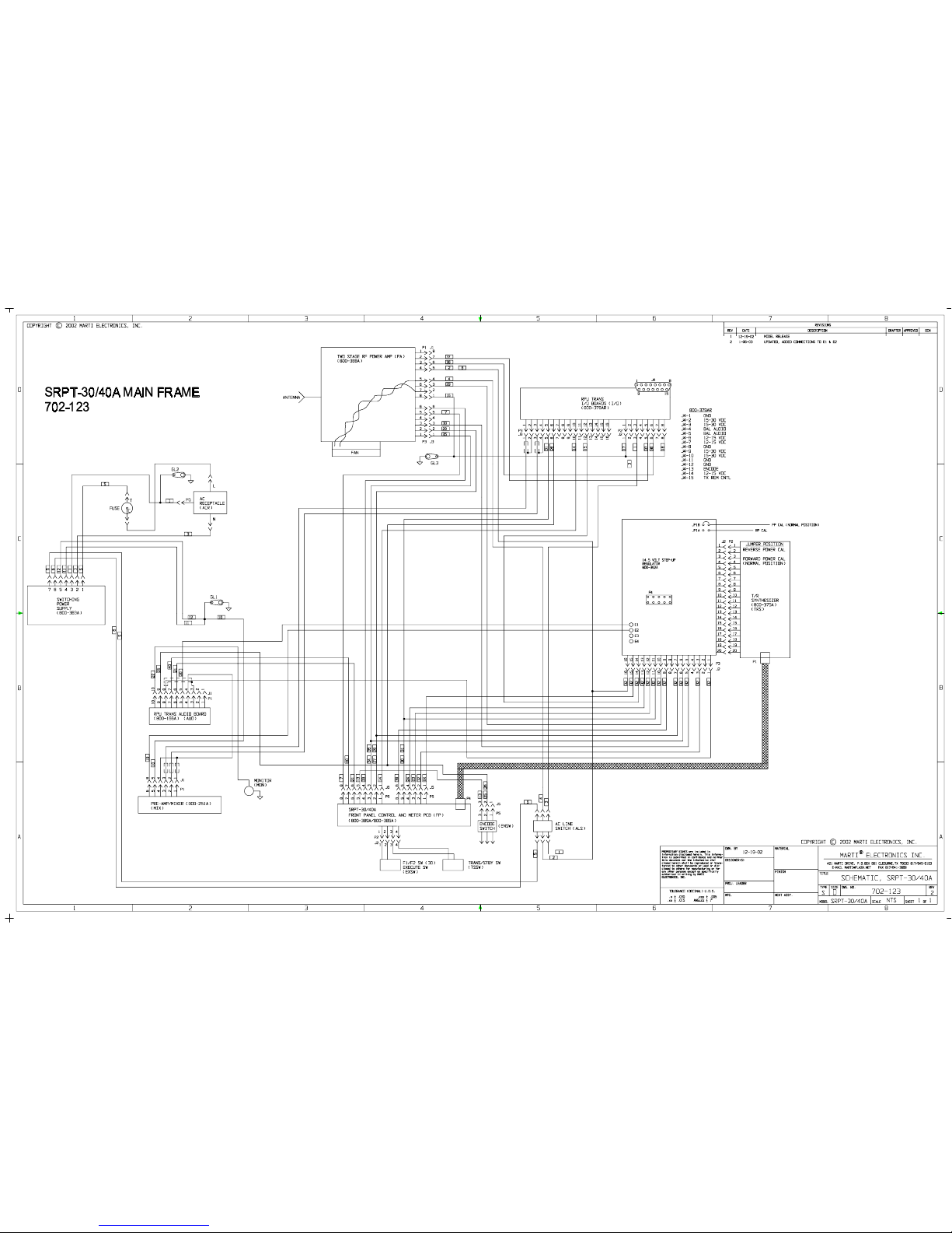
Page 98
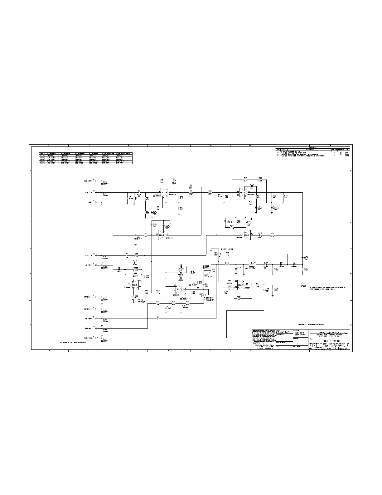
Page 99
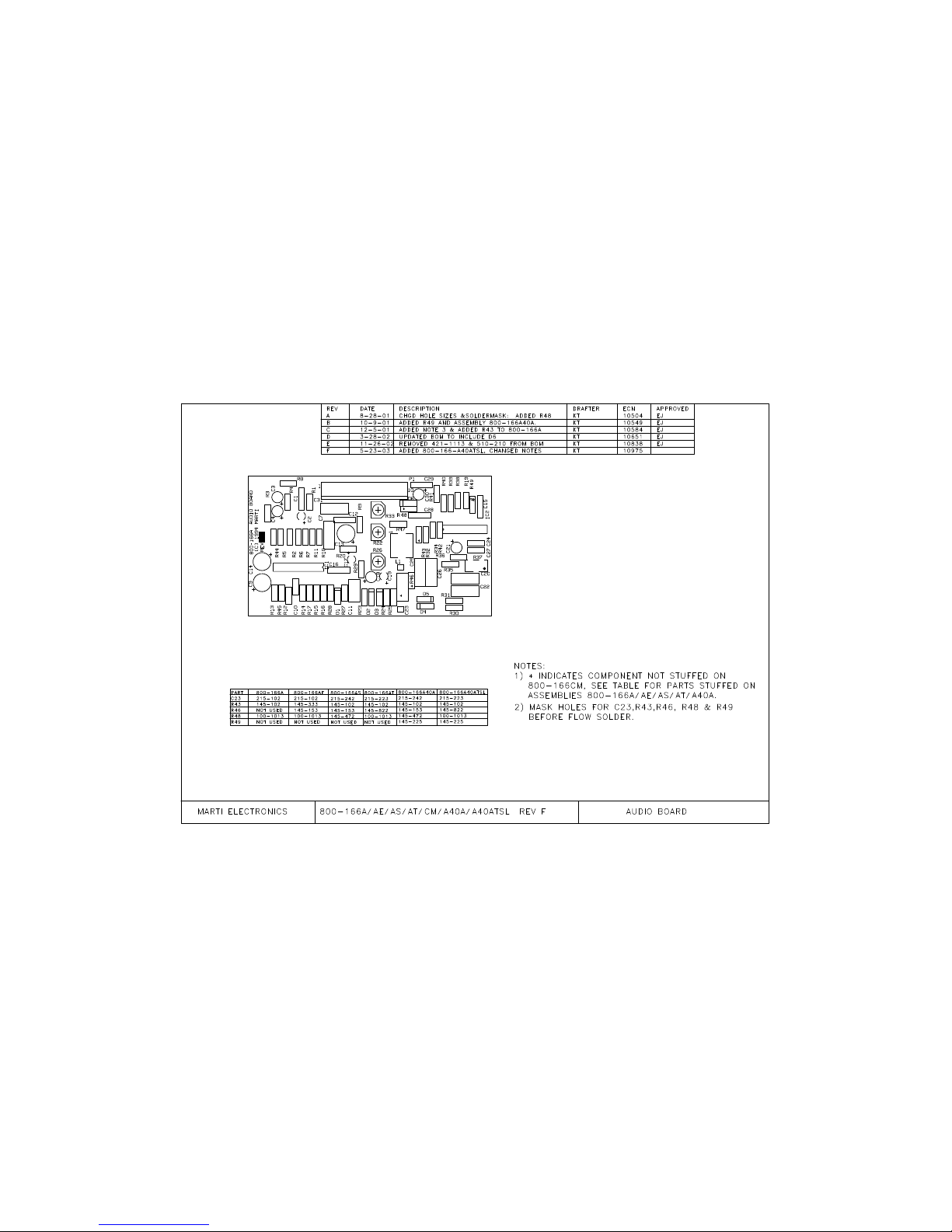
Page 100
 Loading...