

Page 1
V 600
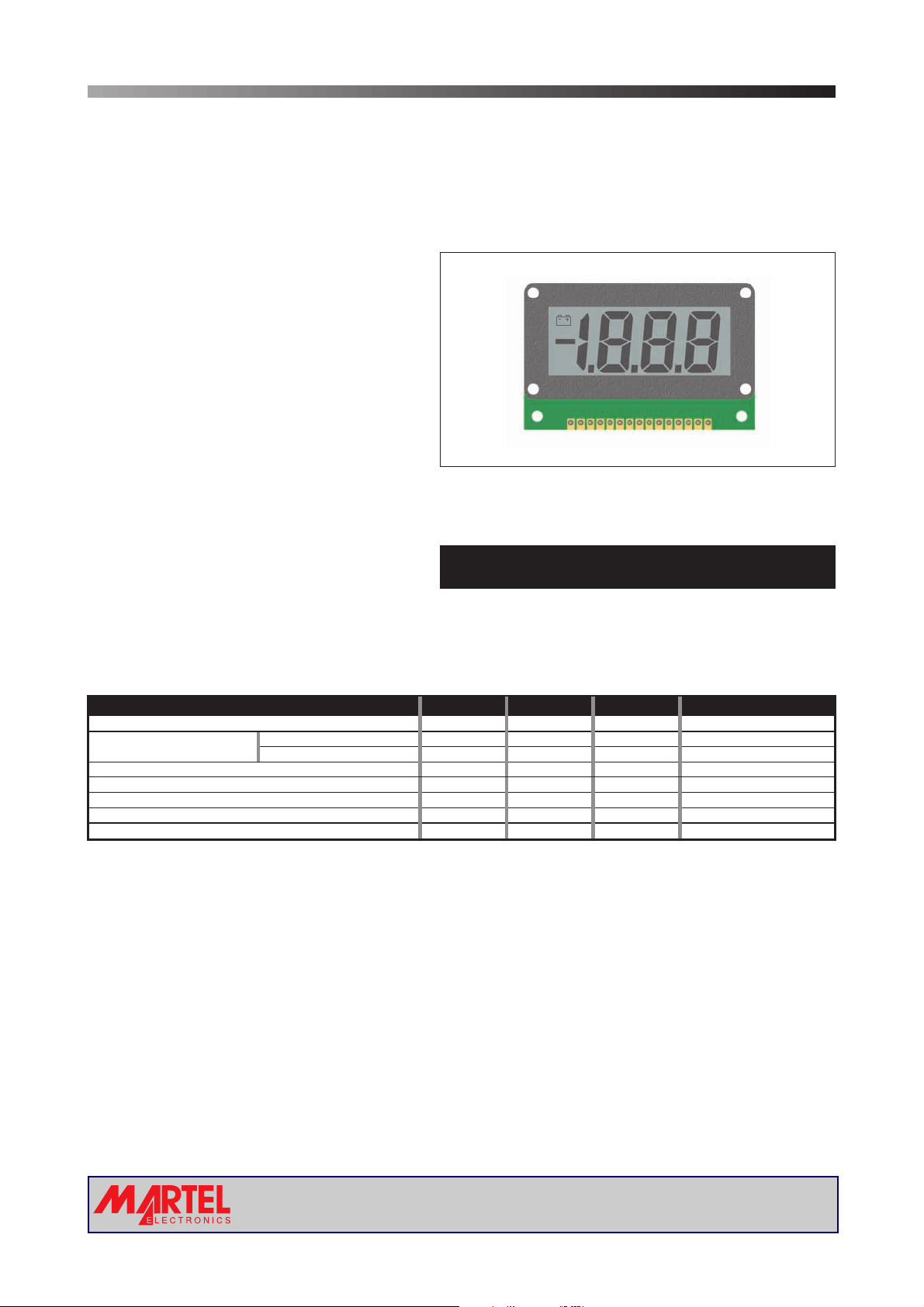
3½ Digit LCD Voltmeter Module
PRODUCT DESCRIPTION
The V 600 features a 200mV d.c. measurement range with auto-zero and auto-polarity. Decimal points are user
selectable. The display features a low battery warning annunciator, which can be driven by external circuitry. The
module's low cost meansit will suit most high volume applications.
FEATURES
• Low Cost
•15
mm (0.6") Digit Height
• 200mV d.c. Full Scale Reading
• 1mA (typ) @ +9V d.c. Power Supply
•
Auto-zero and Auto-polarity
• User Selectable
•
Compatible with Industry-Standard Types
•
Supplied with Mounting Bezel
Decimal Points
TYPICAL APPLICATIONS
• High Volume, Low Cost Systems
• Power Supply Monitoring
• Panel-Mount Indication
ORDERING INFORMATION
Stock Number
Standard Meter V 600
ELECTRICAL SPECIFICATIONS
Specification Min. Typ. Max. Unit
Accuracy (overall error) * 0.25 % (±3 counts)
Linearity 0-1000 reading ±3 counts
Sample rate 3 samples/sec
Operating temperature range 0 50 °C
Temperature stability 300 ppm/°C
Supply voltage 7.0 9 12 V d.c.
Supply current 1 2 mA
* To ensure maximum accuracy, re-calibrate periodically.
0-2000 reading counts
±5
SAFETY
To comply with the Low Voltage Directive(LVD 93/68/EEC), inputvoltagestothemodule’spinsmustnotexceed
60Vdc. The usermustensurethat the incorporation of thepanel meter into theuser’s equipmentconforms to the
relevant sections of BS EN 61010 (Safety Requirements for Electrical Equipment for Measuring, Control and
Laboratory Use).
www.martelmeters.com
Page2of4Page 2 of 4
page 1 of 4
Page 2
V 600
3½ Digit LCD Voltmeter Module
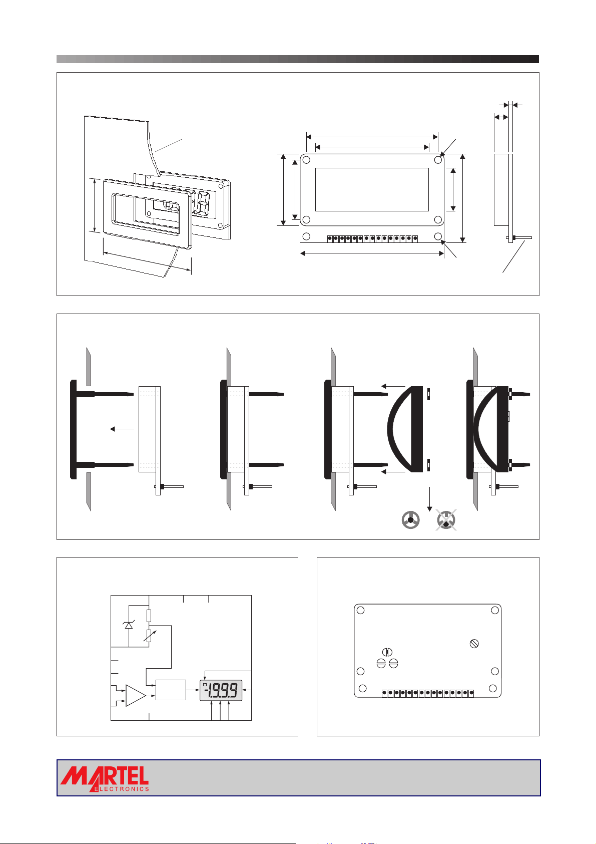
DIMENSIONS
34.5 (1.36)
64.5 (2.54)
PANEL FITTING
Panel
All dimensions in mm (inches)
Panel thickness: 1.0 - 3.0
(0.04 - 0.12)
Panel cut-out: 62.0 - 32.0
(2.44 - 1.26)
30 (1.18)
25.0 (0.98)
55 (2.17)
47 (1.86)
60 (2.36)
6.6 (0.26)
2.8 (0.11) dia
38.1 (1.5)
17.7 (0.7)
2.8 (0.11) dia
1.6 (0.06)
Pin Pitch 2.5 (0.1)
Meter
Bezel
1 2
FUNCTIONAL BLOCK DIAGRAM
ROH
ROL
LOBAT
BP
COM
RFH
RFL
INHI
INLO
Vref
VDD
CAL
+
_
A/D
Fixing Clip
Fastener
3 4
PIN CONFIGURATION
REAR VIEW
BP BAT
BP
LO BAT
DP1
DP2
DP3
ROH
ROL
COM
RFH
RFL
VSS
115
INLO
(rear view)
INHI
TEST
VDD
VSS
DP321
www.martelmeters.com
Page2of4Page 2 of 4
page 2 of 4
Page 3
V 600
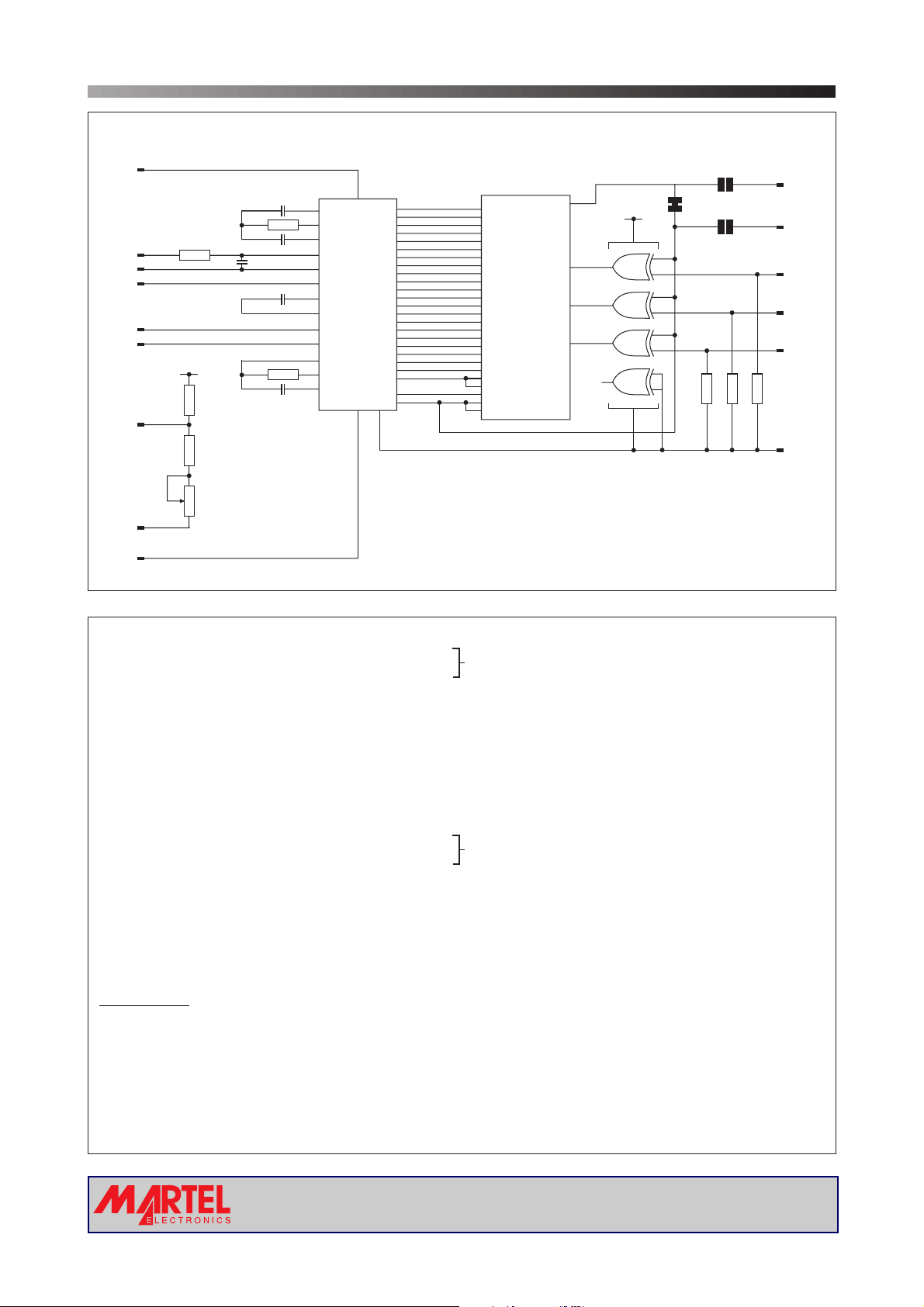
CIRCUIT DIAGRAM
15
VDD
R1
300k
R2
1M
13
INHI
INLO
COM
RFH
RFL
ROH
ROL
VSS
12
8
9
10
VDD
6
7
11
R6
100k
R5
3k
R4
1.5k
100nF
C3
68nF
220nF
100nF
R3
3½ Digit LCD Voltmeter Module
BAT
1
517
C1
C2
C4
100k
C5
100pF
V+
27
INT
28
BUF
29
A/Z
31
IN HI
30
IN LO
32
COM
34
CREF+
33
CREF-
36
REF HI
35
REF LO
40
OSC1
39
OSC2
38
OSC3
a1
416
b1
315
c1
214
d1
813
e1
618
f1
719
g1
12 21
a2
11 20
b2
10 11
c2
910
d2
IC1
14 9
e2
13 22
f2
25 23
g2
23 25
a3
16 24
b3
24 7
c3
15 6
d3
18 5
e3
17 26
f3
22 27
g3
19 3
bc4 b4
20 2
POL
21 1
BP
V-
TEST
37
26
a1
b1
c1
d1
e1
f1
g1
a2
b2
c2
d2
e2
f2
g2
a3
b3
c3
d3
e3
f3
g3
28
c4
POL
COM
30
COM
LCD1
LOBAT
DP1
DP2
DP3
29
1.999
4
19.99
8
199.9
12
IC2
4070
VDD
4
3
11
10
IC2B
IC2A
IC2D
IC2C
BP
14
5
6
2
1
12
13
9
8
7
R9
1M
R81MR7
2
LO BAT
1
BP
3
DP1
4
DP2
5
DP3
1M
14
TEST
PIN FUNCTIONS
1. BP Backplane connection from voltmeterIC.
2. LO BAT LCD connection to "Low Battery"annunciator.
3. DP1 Connect to V+ to displayDecimal Point 1(1.999).
4. DP2 Connect to VDD to displayDecimal Point 2(19.99).
5. DP3 Connect to VDD to displayDecimal Point 3(199.9).
6. ROH Positiveoutput frominternalreference.
7. ROL Negative output from internal reference.
8. COM The ground for the analoguesection ofthe A/Dconverter, heldactively at2.8V(nom) below VDD.
COM must not be allowedto sinkexcessivecurrent(>100 A) by connecting it directlyto ahighervoltage.
9. RFH Positiveinput for reference voltage.
10. RFL Negative input for reference voltage.
11. VSS Negative powersupply connection.
12. INLO Negativemeasuring inputwithreferenceto IN HI.
13. INHI Positive measuring input with referenceto INLO.
14. TEST Connecting thispin toVDD toturnon display segments "-1888".
It should not be operatedfor morethan afewseconds as the DC voltageapplied tothe LCDmay"burn" the display.
This pin is nominally at5V belowVDDandis the ground forthe digitalsection ofthe meter, itcan beused asanegative
supply to power external logicup toamaximumof 1mA.
15. VDD Positivepower supplyconnection.
Solder Links:
BP Normally Open.
BAT Normally Open.
See application diagram on next page.
µ
Analogue inputs must be no closer than 1V
to either the positive or negative supply.
www.martelmeters.com
page 3 of 4
Page 4

V 600
SCALING
Two resistors Ra and Rb
may be used to alter the
full scale reading (FSR) of
the meter - see table. The
Voltage
Vin 200V 1M 1k
meter will have to be recalibrated by adjusting the
calibration potentiometer
on the rearof the module.
Current
Iin 20mA 0R 10R
*Ensure that Ra is rated for high voltage use.
APPLICATIONS
Do not connect more than one meter to the same power supply
if the meters cannot use the same signal ground. Taking any
input beyond thepower supply railswill damage the meter.
FSR Ra Rb
2V 910k 100k
20V 1M 10k
2000V* 1M 100R
200 A 0R 1k
µ
2mA 0R 100R
200mA 0R 1R
3½ Digit LCD Voltmeter Module
Ra
+
Vin or inI
-
Normally
SHORTED
Cut to
OPEN
Rb
INHI
INLO
Normally
OPEN
Solder to
SHORT
+7 to +12V
15
VDD
DP3
V 600
VSS
±200mV
+
-
13
12
10
8
7
IN HI
IN LO
COM
ROL
RFL
11
0V 0V
Measuring an input voltage referenced to a floating supply,
i.e. the input voltage and the meter's power supply are
isolated from each other.
+3.5 to +6.0V
15
VDD
DP3
V 600
VSS
ROH
RFH
±200mV
+
-
13
12
10
8
7
IN HI
IN LO
COM
ROL
RFL
11
-3.5 to -6.0V
Measuring a single ended input referenced to supply, i.e.
the input voltage and the meter's power supply share the
same 0V rail.
+7 to +12V
15
I+
5
I-
13
12
109
8
76
IN HI
IN LO
COM
ROLROH
RFLRFH
VDD
DP3
V 600
VSS
ROH
RFH
5
6
9
11
Measuring a current referenced to a floating supply, i.e. the
current being measured and the meter's power supply are
isolated from each other.
V+
4070
BP
14
1
LO BAT
2
TEST
1M
1M
5
6
9
470k
SET
THRESHOLD
BC 237
15
VDD
V 600
VSS
11
V-
Driving the Battery annunciator with associated external logic
and low battery detection circuitry.
Specifications liable to change without prior warning V 600 Issue 2 November/2001 M.C. Applies to V 600/2
Page4of4Page 4 of 4
 Loading...