

Page 1
V1
3½ Digit LCD Voltmeter Module
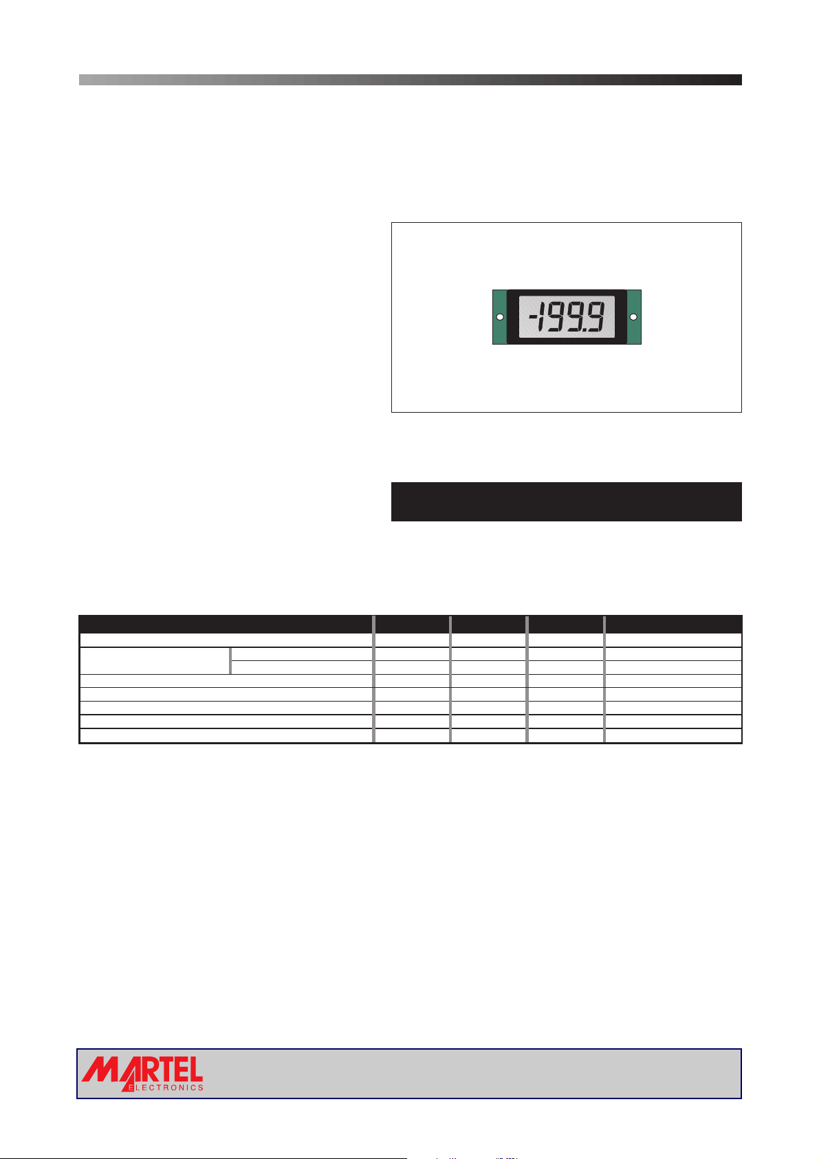
PRODUCT DESCRIPTION
This low cost compact LCD voltmeter module is ideally suited for high volume applications. It features an exceptionally
large display ina miniaturepackage and includesauto-zero anduser-selectable decimal points. The module issupplied with
a panel mountingbezel.
FEATURES
• Low Cost
• 6.3
mm (0.25") Digit Height
• 200mV d.c. Full Scale Reading
• 1mA (typ)@ +9V d.c. Power Supply
•
Auto-zero and Auto-polarity
• User Selectable
•
Supplied with Mounting Bezel
Decimal Points
1
REAR VIEW
8
TYPICAL APPLICATIONS
• High Volume, Low Cost Systems
• Power Supply Monitoring
ORDERING INFORMATION
Stock Number
Standard Meter V 1
• Panel-Mount Indication
ELECTRICAL SPECIFICATIONS
Specification Min. Typ. Max. Unit
Accuracy (overall error) * 0.25 % (±3 counts)
Linearity 0-1000 reading ±3 counts
Sample rate 3 samples/sec
Operating temperature range 0 50 °C
Temperature stability 300 ppm/°C
Supply voltage 7.0 9 12 V d.c.
Supply current 1 2 mA
* To ensure maximum accuracy, re-calibrate periodically.
0-2000 reading counts
±5
SAFETY
To comply with the Low Voltage Directive(LVD 93/68/EEC), inputvoltagestothemodule’spinsmustnotexceed
60Vdc. The usermustensurethat the incorporation of thepanel meter into theuser’s equipmentconforms to the
relevant sections of BS EN 61010 (Safety Requirements for Electrical Equipment for Measuring, Control and
Laboratory Use).
www.martelmeters.com
Page2of4Page 2 of 4
page 1 of 4
Page 2
V1
3½ Digit LCD Voltmeter Module
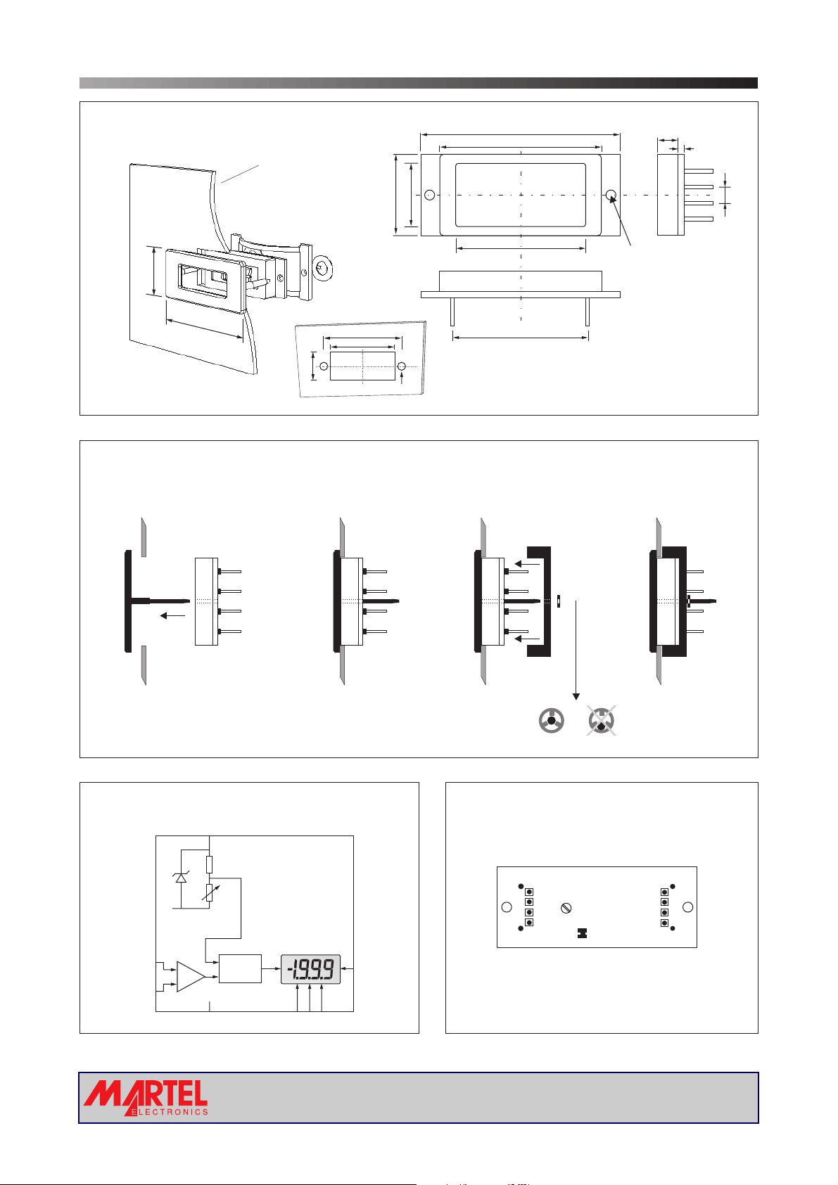
DIMENSIONS
Panel thickness: 1.0 - 3.0
18.0 (0.71)
38.0 (1.50)
PANEL FITTING
Panel
Meter
All dimensions in mm (inches)
(0.04 - 0.12)
14.0 (0.55)
34.0(1.34)
31.0(1.22)
15.0 (0.59)
2.5(0.1) dia
8.0 (0.31)
38.0 (1.50)
30.0 (1.18)
23.0 (0.91)
21.0 (0.83)
Fixing Clip
5.5 (0.22)
dia 2.5 (0.1)
1.6 (0.06)
2.54
(0.1)
Bezel
1 2 4
FUNCTIONAL BLOCK DIAGRAM
V+
Vref
CAL
COM
INHI
INLO
+
_
A/D
XDP
Fastener
3
PIN CONFIGURATION
V+
VINHI
INLO
REAR VIEW
CAL
L1
15
48
(rear view)
XDP
DP1
DP2
DP3
V-
DP321
www.martelmeters.com
Page2of4Page 2 of 4
page 2 of 4
Page 3

V1
CIRCUIT DIAGRAM
1
V+
R1
180k
R2
1M
3
INHI
INLO
4
L1
V+
R6
100k
R5
3k
100nF
C3
100nF
220nF
100nF
R3
3½ Digit LCD Voltmeter Module
1
512
C1
C2
C4
100k
C5
100pF
V+
27
INT
28
BUF
29
A/Z
31
IN HI
30
IN LO
32
COM
34
CREF+
33
CREF-
35
REF LO
36
REF HI
40
OSC1
39
OSC2
38
OSC3
a1
411
b1
310
c1
29
d1
815
e1
613
f1
714
g1
12 19
a2
11 18
b2
10 17
c2
916
d2
IC1
14 21
e2
13 20
f2
25 7
g2
23 24
a3
16 23
b3
24 5
c3
15 22
d3
18 4
e3
17 25
f3
22 2
g3
19
bc4 b4
20 29
POL
21 1
BP
V-
TEST
37
26
a1
b1
c1
d1
e1
f1
g1
a2
b2
c2
d2
LCD1
e2
f2
g2
a3
b3
c3
d3
e3
f3
g3
26
27
c4
POL
COM
30
COM
DP1
DP2
DP3
LOBAT
199.9
8
19.99
6
1.999
3
28
6
DP1
7
DP2
8
DP3
R81MR7
R9
1M
1M
R4
1.5k
2
V-
R10
100k
Q1
3904
PIN FUNCTIONS
1. V+ Positivepower supplyconnection.
2. V- Negative power supply connection.
3. INHI Positivemeasuring inputwith referencetoIN LO.
4. INLO Negative measuring input with referenceto INHI.
5. XDP Connect to DP1, 2 or3 todisplayrequireddecimal point.
6. DP1 Connect to XDP to displayDecimal Point 1(199.9).
7. DP2 Connect to XDP to displayDecimal Point 2(19.99).
8. DP3 Connect to XDP to displayDecimal Point 3(1.999).
Solder Links:
L1 Normally Closed, connects COMto INLO.
V+
R11
100k
Analogue inputs must be no closer than 1V
to either the positive or negative supply.
5
XDP
www.martelmeters.com
page 3 of 4
Page 4
V1
SCALING
Two resistors Ra and Rb
may be used to alter the
full scale reading (FSR) of
the meter - see table. The
Voltage
Vin 200V 1M 1k
meter will have to be recalibrated by adjusting the
calibration potentiometer
on the rearof the module.
Current
Iin 20mA 0R 10R
*Ensure that Ra is rated for high voltage use.
APPLICATIONS
Do not connect more than one meter to the same power supply
if the meters cannot use the same signal ground. Taking any
input beyond thepower supply railswill damage the meter.
+7.0 to +12V +7.0 to +12V
11
V+
FSR Ra Rb
2V 910k 100k
20V 1M 10k
2000V* 1M 100R
200 A 0R 1k
µ
2mA 0R 100R
200mA 0R 1R
3½ Digit LCD Voltmeter Module
Ra
+
Vin or inI
-
Normally
SHORTED
Cut to
OPEN
V+
Rb
INHI
INLO
Normally
OPEN
Solder to
SHORT
L1
V1
V-
DP1 DP1
XDP XDP
±200mV
+
-
33
IN HI
44
IN LO
22
0V 0V
Measuring an input voltage referenced to a floating supply,
i.e. the input voltage and the meter's power supply are
isolated from each other. Check Link L1 is closed.
+3.5 to +6.0V
1
V+
L1
V1
V-
DP1
XDP
±200mV
+
-
3
4
IN HI
IN LO
2
66
5
I+
I-
Measuring a current referenced to a floating supply, i.e. the
current being measured and the meter's power supply are
isolated from each other. Check Link L1 is closed.
IN HI
IN LO
L1
5
V1
V-
6
5
-3.5 to -6.0V
Measuring a single ended input referenced to supply, i.e.
the input voltage and the meter's power supply share the
same 0V rail. Check Link L1 is open.
Specifications liable to change without prior warning V 1 Issue 3 January/2002 M.C. Applies to V 1/2
Page4of4Page 4 of 4
www.lascarelectronics.com
www.martelmeters.com
page 4 of 4
 Loading...