

Page 1
SP 5-1710-BL
Page 2 of 4
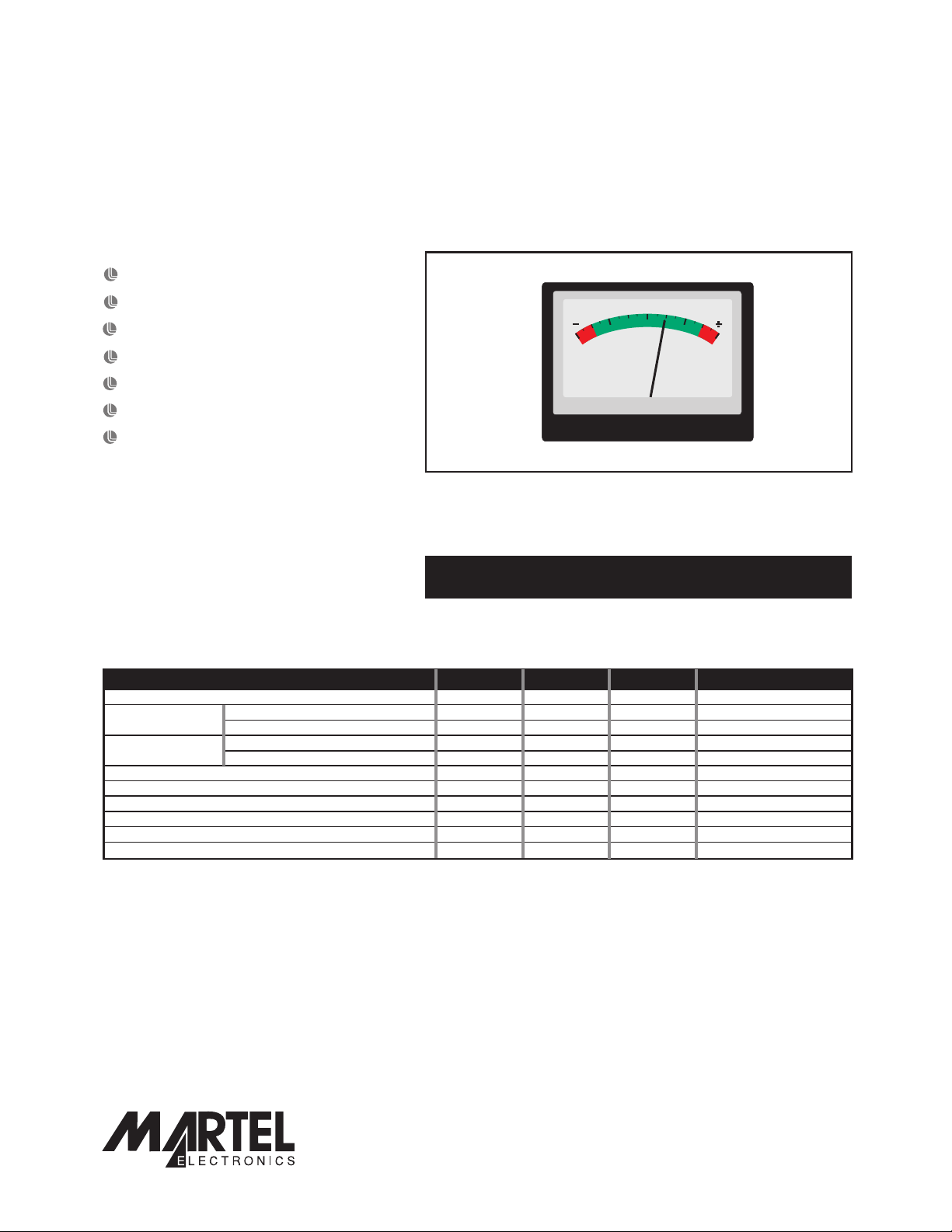
17 Segment Analogue LCD Meter
This low cost, compact indicator is ideally suited for low or high volume applications. The meter features a 17
segment LCD to display 0-1V or -1V-0-1V d.c. full scale reading. Other voltages and currents canbe indicated via
the addition of 2 external scaling resistors. The meter can be used in applications where the order of magnitude
of the reading is more important than the value ofthe reading itself. Itallows the operator to scan the display and
receive a quick visual feedback. The module is mounted into the panel, using the supplied clip. A rubber seal is
included, providing splashproof protection for the unitwhen fitted to the meter during installation.
17 Segment LCD
LED Backlighting
0
Colour Scale
0-1V and -1V-0-1V d.c. Ranges
No Calibration Required
Screw Terminal Connection
Splashproof
ORDERING INFORMATION
Stock Number
Standard Indicator SP 5-1710-BL
ELECTRICAL SPECIFICATIONS
Specification Min. Typ. Max. Unit
Accuracy (overall error) * 1 Segment (±1)
Full scale reading (left/right hand zero position) 0 1 V d.c.
Resolution 62.5 mV d.c.
Sample rate 4 samples/sec
Operating temperature range 0 50 °C
Supply voltage (meter only, not LED backlighting) 5 9 12 V d.c.
Supply current (meter only, not LED backlighting) 6 10 mA
Supply voltage for LED backlighting** 4.5 5 5.5 V d.c.
Supply current for LED backlighting @5V d.c.** 50 mA
(centre zero position) -1 1
(left/right hand zero position)
(centre zero position) 125 mV d.c.
V d.c.
* At voltages above 1V d.c. or below -1V d.c., the display flashes.
** For backlighting supply voltages in excess of 5Vd.c., consult Various Operating Modes on page 4.
SAFETY
To comply with the Low Voltage Directive (LVD 93/68/EEC), input voltages to the module’s pins must not exceed
60Vdc. The user must ensure that the incorporation of the panelmeter into the user’s equipment conforms to the
relevant sections of BS EN 61010 (Safety Requirements for Electrical Equipment for Measuring, Control and
Laboratory Use).
LASCAR ELECTRONICS LTD.
MODULE HOUSE
WHITEPARISH
WILTSHIRE SP5 2SJ
UK
TEL: +44 (1794) 884567
FAX: +44 (1794) 884616
E-mail: sales@lascar.co.uk
Specifications liable to change without prior warning SP 5-1710-BL Issue 1 January/2004 M.C. Applies to SP 5-1710/2
PO Box 770, Londonderry, NH 03053 1-800-821-0023
www.martelcorp.com
LASCAR ELECTRONICS INC.
3750 WEST 26th STREET
ERIE
PA 16506
USA
TEL: +1 (814) 835 0621
FAX: +1 (814) 838 8141
E-mail: us- sales@lascarelectronics.com
www.lascarelectronics.com
LASCAR ELECTRONICS (HK) LIMITED
FLAT C, 5/FL., LUCKY FTY. BLDG.
63-65 HUNG TO ROAD
KWUN TONG KOWLOON
HONG KONG
TEL: +852 2797 3219
FAX: +852 2343 6187
E-mail: b4lascar@samsongroup.com.hk
Page2of4
Page1of4
Page 2
Page 2 of 4
SP 5-1710-BL
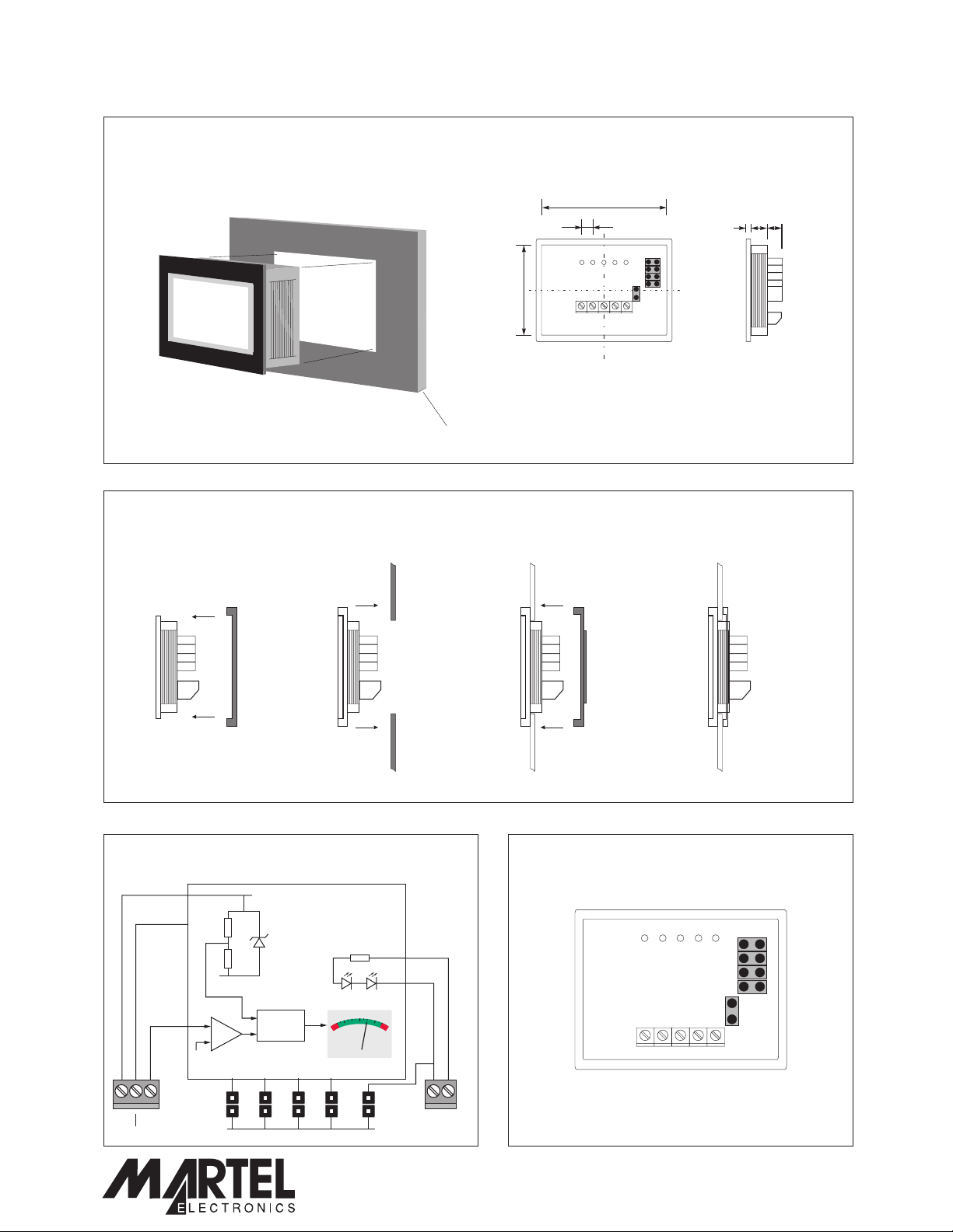
DIMENSIONS
All dimensions in mm (inches)
47.0 (1.85)
35.0 (1.38)
2.54 (0.1)
34.0 (1.34)
17 Segment Analogue LCD Meter
46.0 (1.81)
ab c
a. 0.75 (0.03)
b. 6.75 (0.27)
c. 9.5 (0.37)
Panel thickness: 1.0 - 2.0
PANEL FITTING
Panel
Module Seal
1
2 34
FUNCTIONAL BLOCK DIAGRAM
(0.04 - 0.08)
CONNECTIONS
(rear view)
V+
Vref
V+
0V
Vin
BL+
+
_
0V
V+ BL-Vin BL+
0V
Specifications liable to change without prior warning SP 5-1710-BL Issue 1 January/2004 M.C. Applies to SP 5-1710/2
J1 J2 J3 J4 JBL
0V
A/D
BL-
PO Box 770, Londonderry, NH 03053 1-800-821-0023
www.lascarelectronics.com
www.martelcorp.com
J1
J2
J3
J4
JBL
Page2of4
Page2of4
Page 3

SP 5-1710-BL
17 Segment Analogue LCD Meter
SCREW TERMINAL FUNCTIONS
V+ Positive power supply to themeter.
0V 0V power supply to the meter.
Vin Positive measuring input,with reference to 0V.
BL+ Positivepowersupply to the LED backlighting.
BL- Negative
power supply to the LED backlighting.
JUMPER LINK FUNCTIONS
J1. Not fitted: The module has a 0 to1V d.c. full scale range (defaultsetting).
Fitted: The module has a -1Vto +1V d.c. full scale range.
The scale annunciators (-, 0, +)are visible. This overrides links J3 and J4.
J2. Not fitted: The input voltage is not inverted(default setting).
Fitted: The input voltage is invertedinside the meter.
J3. Not fitted: The scale annunciators (-,0,+) are notdisplayed.
Fitted: The scale annunciators (-,0,+) aredisplayed. This over rides linkJ4.
J4. Not fitted: The scale annunciator (0) is notdisplayed.
Fitted: The scale annunciator (0) isdisplayed.
J BL. Not fitted: LED backlightingis not required or V+ exceeds5V.
Fitted: To switchon the LED backlighting when V+=5V, fit JBL to connectBL- to 0V.
If V+ exceeds 5V, then a seriesresistormust be fitted in the backlightingcircuit. See
the application diagrams on this datasheetfor details.
Specifications liable to change without prior warning SP 5-1710-BL Issue 1 January/2004 M.C. Applies to SP 5-1710/2
PO Box 770, Londonderry, NH 03053 1-800-821-0023
www.martelcorp.com
www.lascarelectronics.com
Page3of4
Page 4

SP 5-1710-BL
SCALING
Two external resistors may be used to alter the
full scale reading of the meter - see table for
sample values. Alter natively, use the
following formulae to calculate Ra and Rb.
Select the nearest available standard resistor.
To achieve optimum accuracy, use 1% metal
film resistors. Ensure solder link La is cut
when fitting Ra.
Required F.S.R. Ra Rb
10V 910k 100k
100V 1M 10k
1mA 0R 1000R
10mA 0R 100R
100mA 0R 10R
1A 0R 1R
Voltage
+
-
Current
+
-
17 Segment Analogue LCD Meter
Ra
Load
I
FSD
Vin
Rb
V2
0V
Vin
V2
Rb
0V
Ra=1M
Rb=Ra.
Rb=I1V
V2 .
V1-V2
FSD
VARIOUS OPERATING MODES
J1 not fitted
J2 not fitted
J3 not fitted
0-1Vd.c.
J4 not fitted
+
-
Vin
V+
0V
Indicating a voltage in the range 0 to 1V d.c.
Close switch S1 to turn on the backlighting.
Jumper link JBL must NOT be fitted.
J1 fitted
J2 not fitted
V+
0
0V
J3 fitted
J4 fitted
+
Vin
Rb =I1V
+
7805
-
-
Battery
Indicating battery
charge/discharge current.
Ensure jumper link LK1 is fitted.
5...12Vd.c.
S1
BL+
BL-
R=
V+ - 5V
R
0V
To charger / load circuit
0.05
I
5...12Vd.c.
V+
0V
0V
5...12Vd.c.
Vin
J1 not fitted
J2 fitted
J3 not fitted
J4 not fitted
0V
J1 not fitted
J2 not fitted
J3 not fitted
J4 not fitted
Power
Supply
J1 not fitted
J2 not fitted
J3 not fitted
J4 not fitted
Load
Vin
Rb =I1V
Indicating a d.c. current.
V+
Vin
Vin1 Vin2
0V
V+
0V
Indicating 2 voltages
J1 not fitted
J2 not fitted
J3 not fitted
J4 not fitted
I
Ra1
Vin
5...12Vd.c.
V+
Power
Supply
Load
R=
b2
1V
Vin
I
Current
V+
0V
Rb1
Voltage
0V
J1 not fitted
J2 not fitted
J3 not fitted
J4 not fitted
0V
Simultaneous d.c. Voltage and Current Indication.
Specifications liable to change without prior warning SP 5-1710-BL Issue 1 January/2004 M.C. Applies to SP 5-1710/2
PO Box 770, Londonderry, NH 03053 1-800-821-0023
www.lascarelectronics.com
Page4of4
www.martelcorp.com
 Loading...