

Page 1

SP 5-1200-BL
2-Wire Signal-Powered Meter
This low cost, compact indicator is ideally suited for low or high volume applications. SP 5-1200-BL is an easy to
mount LCD digital panel meter. Themodulefeaturesa 4 to 25V measurement range with 100mV resolution and
is powered from the signal it is measuring. Only valid readings are displayed; the module indicates "LO" at
voltages below 4V and "HI" at voltages above 25V. Screw terminals allow for quick and easy connection. The
module is panel mounted using the metal clip provided and a rubber seal is included, providing splashproof
protection for theunitwhen fitted to the meter during installation.
2-Wire Operation (excluding backlighting)
4 to 25V d.c. Full Scale Reading
18mm / 0.7" LCD Digit Height
Reverse Polarity Protection
No Calibration Required (pre-calibrated for use)
Splashproof
LED Backlighting (via separate supply)
Screw Terminal Connections
ELECTRICAL SPECIFICATIONS
Specification Min. Typ. Max. Unit
Accuracy (overall error) 0.2 V (±1 count)
Linearity 1 count
Valid displayed reading* 4.0 25.0 V d.c.
Resolution 100 mV d.c.
Sample rate 3 samples/sec
Operating temperature range 0 50 °C
Supply voltage Meter 3 50 V d.c.
Supply current Meter (@ 9V d.c.) 1.5 mA
* At voltages below 4.0V d.c., the LCD will display and will ultimately go blank.
At Voltages in excess of 25.0V d.c., the LCD will display .
Do NOT exceed 50V d.c., as this may damage the meter.
The module includes reverse polarity protection up to 30V for up to 30 seconds.
Operation and accuracy at voltages above 25.0V or below 4.0V are not specified.
Backlighting 5 V d.c.
Backlighting (@ 5V d.c.) 50 mA
LO
HI
+
SAFETY
To comply with the Low VoltageDirective (LVD93/68/EEC), input voltages to the module’s connections must not
exceed 60Vd.c. The user must ensure that the incorporation of the meter into the user ’s equipment conforms to
the relevant sections of BS EN 61010 (Safety Requirements for Electrical Equipment for Measuring, Control and
Laboratory Use).
LASCAR ELECTRONICS LTD.
MODULE HOUSE
WHITEPARISH
WILTSHIRE SP5 2SJ
UK
TEL: +44 (1794) 884567
FAX: +44 (1794) 884616
E-mail: sales@lascar.co.uk
Specifications liable to change without prior warning SP 5-1200-BL Issue 4 November/2003 M.C. Applies to SP 5-1200/2
PO Box 770, Londonderry, NH 03053 1-800-821-0023
www.martelcorp.com
LASCAR ELECTRONICS INC.
3750 West 26th Street
Erie
PA 16506
USA
TEL: +1 (814) 835 0621
FAX: +1 (814) 838 8141
E-mail: us-sales@lascarelectronics.com
LASCAR ELECTRONICS (HK) LIMITED
FLAT C, 5/FL., LUCKY FTY. BLDG.
63-65 HUNG TO ROAD
KWUN TONG KOWLOON
HONG KONG
TEL: +852 2797 3219
FAX: +852 2343 6187
E-mail: b4lascar@samsongroup.com.hk
Page 2
SP 5-1200-BL
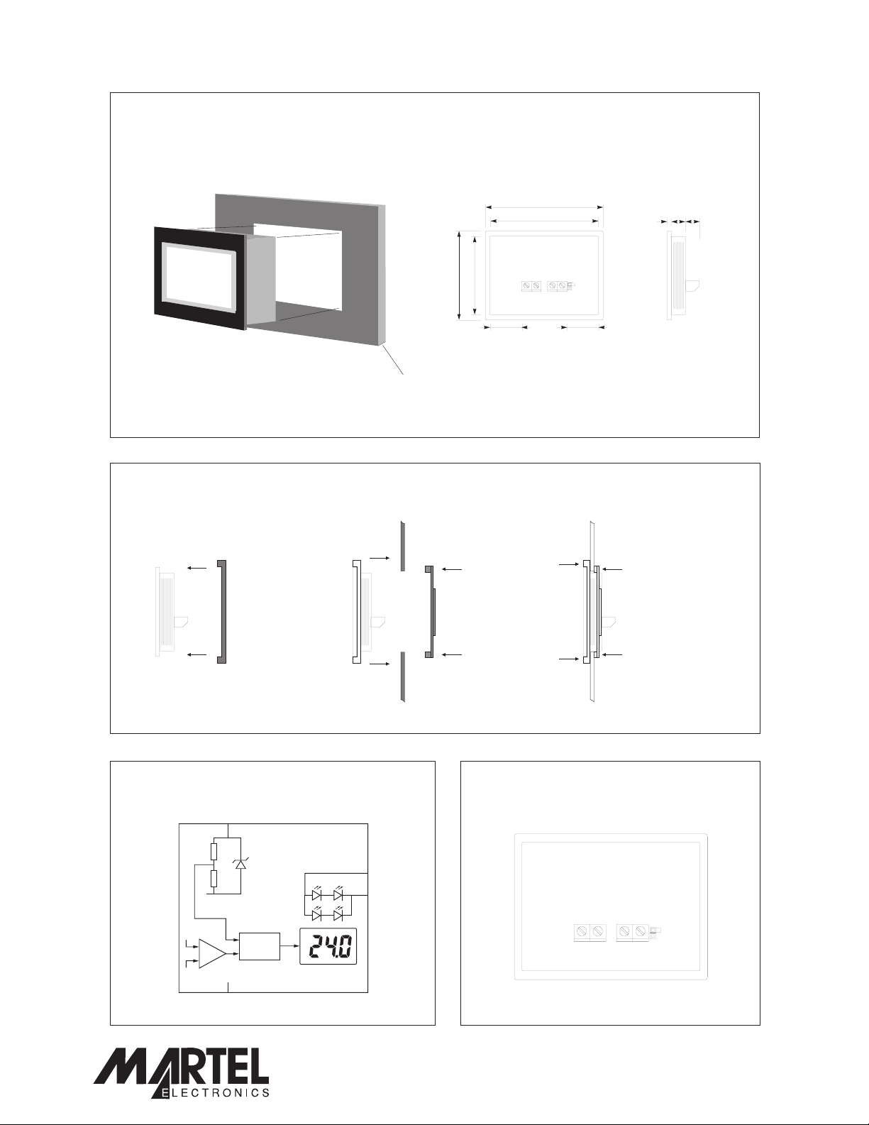
DIMENSIONS
All dimensions in mm (inches)
2-Wire Signal-Powered Meter
47.0 (1.85)
35.0 (1.38)
Panel thickness: 1.0 - 2.0
(0.04 - 0.08)
PANEL FITTING
Panel
Module Seal Metal Clip
48.0 (1.89)
46.0 (1.81)
36.0 (1.42)
34.0 (1.34)
14.4 (0.57) 14.4 (0.57)
ab c
a. 0.95 (0.04)
b. 6.5 (0.26)
c. 8.5 (0.33)
1
FUNCTIONAL BLOCK DIAGRAM
V+
Vref
V+
+
_
0V
Specifications liable to change without prior warning SP 5-1200-BL Issue 4 November/2003 M.C. Applies to SP 5-1200/2
A/D
0V
PO Box 770, Londonderry, NH 03053 1-800-821-0023
2 3
CONNECTIONS
BL+
BL-
www.lascarelectronics.com
(rear view)
V+
0V
BL+
BL-
Page2of3
www.martelcorp.com
Page 3
SP 5-1200-BL
SCREW TERMINAL FUNCTIONS
V+ Positive power supply to the meter / voltage being measured.
0V 0V power supply to the meter / voltage being measured.
BL+ Positivepower supply to the LED backlighting.
BL- Negativepower supply to the LED backlighting.
When the jumper link is placed over both pins, located next to the screw terminals, this connects the 0V of the LED
backlighting to the 0V of the signal being measured. This allows for 3-wire operation of the module.
This connection should only be made if both power supplies can share a common 0V line.
SCALING
This module cannot be re-scaled for other voltage or currentscales.
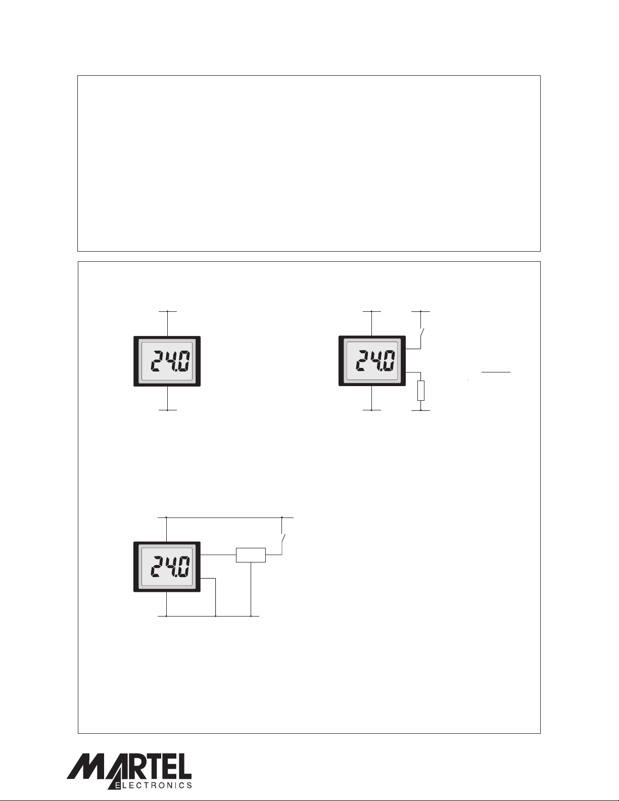
APPLICATIONS
2-Wire Signal-Powered Meter
+4 to +25Vd.c. +4 to +25Vd.c.
V+ V+
0V 0V
0V 0V
Measuring a voltage in the range 4 to 25V d.c.
+7.5 to +25Vd.c.
V+
BL+
BL-
0V
7805*
S1
I/PO/P
* High input
voltage version
V
BL
S1
BL+
BL-
R
0V
Powering the LED backlighting from a separate supply.
Close switch S1 to turn on the backlighting.
Note: - add a series resistor R if the backlighting
supply voltage is higher than 5V d.c.
R=
VBL-5V
0.05
R is not needed
if VBL=5V (then
connect BL- to 0V)
0V
Powering the LED backlighting from the voltage being
measured. The additional load of the backlighting on the
voltage being measured
The voltage regulator may require a heatsink to limit its
temperature rise. Ensure that the maximum input specification
of the voltage regulator considerable exceeds the maximum
peak voltage that can be experienced on the supply line being
monitored.
Specifications liable to change without prior warning SP 5-1200-BL Issue 4 November/2003 M.C. Applies to SP 5-1200/2
may cause this voltage to drop.
PO Box 770, Londonderry, NH 03053 1-800-821-0023
www.lascarelectronics.com
Page3of3
www.martelcorp.com
 Loading...