

Page 1
SP 100
Page 2 of 4
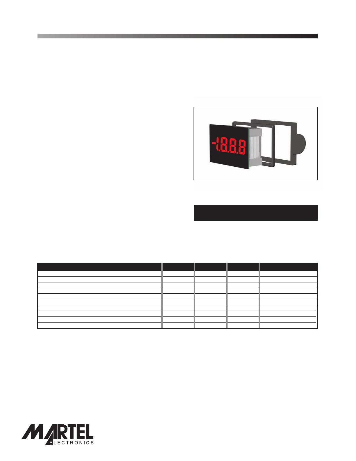
3½ Digit LED Voltmeter Module
PRODUCT DESCRIPTION
The SP 100 features a 200mV d.c. measurement range with auto-zero and auto-polarity. Decimal points are user
selectable. The SP 100 features a negative rail generator which enables the meter to measure a signal referenced to its
own power supply 0V. The bright red LED display ensures excellent readability under low light conditions. It can be
blanked in applications requiring low power operation. The module is easily fitted into the panel, using the fixing clip
provided. The module's low cost means it will suit high and low volume applications. The design of the panel meter's
housing andseal ensures splash proofing in many applications.
FEATURES
•
9.4mm (0.37") Digit Height
• 200mV d.c. Full Scale Reading
• 50mA @ +5V d.c. Power Supply
•
Auto-zero and Auto-polarity
•
Programmable Decimal Points
• Bright Red
• Display Blanking Facility
• Splash Proof
LED Display
TYPICAL APPLICATIONS
• Precision Instrumentation Systems
• Power Supply Monitoring
ORDERING INFORMATION
Stock Number
Standard Meter SP 100
• Test Boxes
• Panel-Mount Indication
ELECTRICAL SPECIFICATIONS
Specification Min. Typ. Max. Unit
Accuracy (overall error) * 0.1 % (±1 count)
Linearity ±1 count
Sample rate 2.5 samples/sec
Operating temperature range 0 50 °C
Warm-up time 10 minute
Temperature stability 150 ppm/°C
Supply voltage 4.75 5 5.25 V
Supply current (DE connected to V+) 50 90 mA
Supply current (DE connected to 0V) µ
Input leakage current (Vin = 0V) 1 10 pA
* To ensure maximum accuracy, re-calibrate periodically.
400 A
SAFETY
To comply with the Low Voltage Directive (LVD 93/68/EEC), input voltages to the module’s pins must not exceed
60Vdc. The user must ensure that the incorporation of the panel meter into the user’sequipment conforms to the
relevant sections of BS EN 61010 (Safety Requirements for Electrical Equipment for Measuring, Control and
Laboratory Use).
LASCAR ELECTRONICS LTD.
MODULE HOUSE
WHITEPARISH
WILTSHIRE SP5 2SJ
UK
TEL: +44 (1794) 884567
FAX: +44 (1794) 884616
E-mail: sales@lascar.co.uk
LASCAR ELECTRONICS INC.
PO BOX 50727
PALO A LTO
CA 94303-0727
USA
TEL: +1 (650) 838 9027
FAX: +1 (650) 833 5432
E-mail: lascarus@pacbell.net
PO Box 770, Londonderry, NH 03053 1-800-821-0023
www.martelcorp.com
www.lascarelectronics.com
LASCAR ELECTRONICS (HK) LIMITED
FLAT C, 5/FL., LUCKY FTY. BLDG.
63-65 HUNG TO ROAD
KWUN TONG
KOWLOON
HONG KONG
TEL: +852 2797 3219
FAX: +852 2343 6187
E-mail: b4lascar@samsongroup.com.hk
Page2of4
Page1of4
Page 2
Page 2 of 4
SP 100
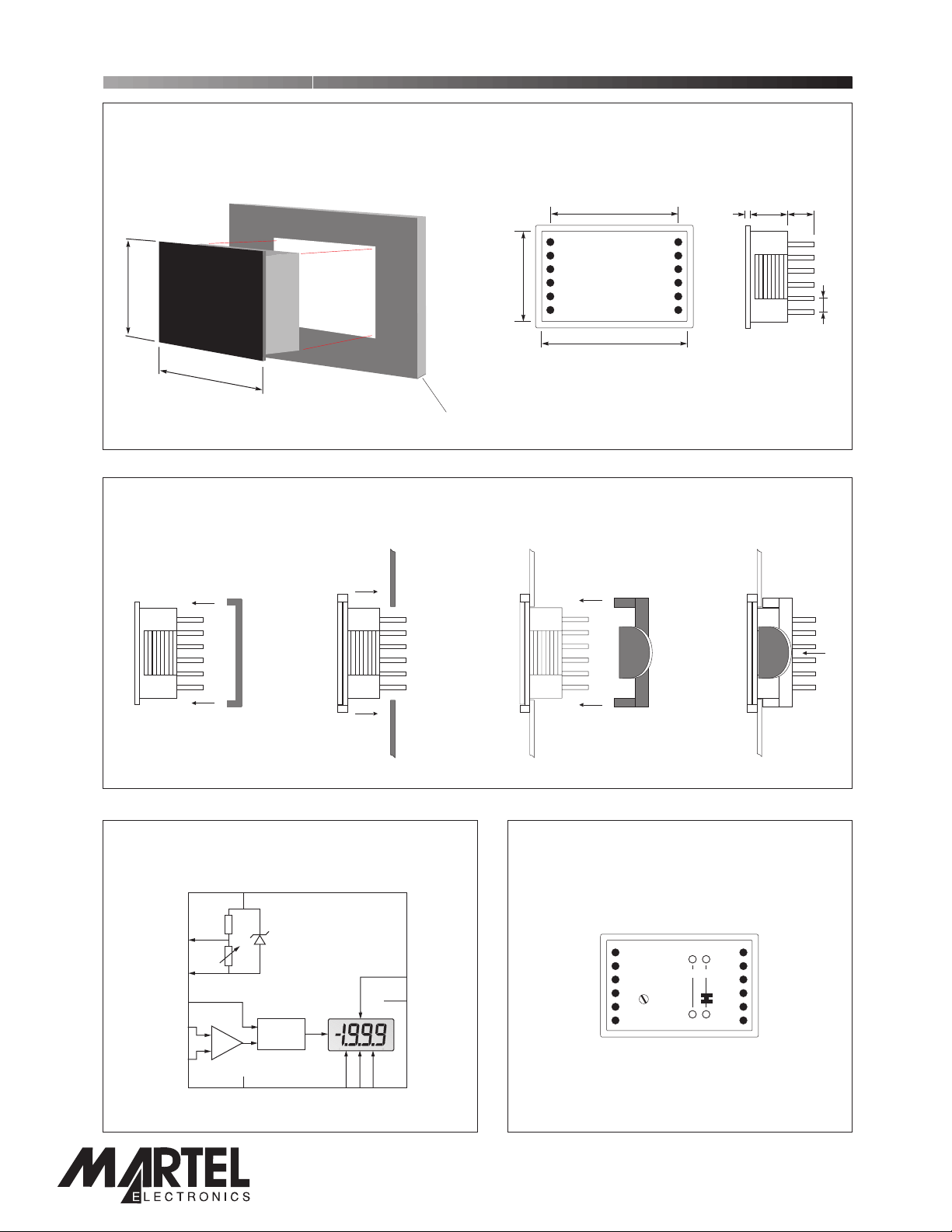
DIMENSIONS
All dimensions in mm (inches)
3½ Digit LED Voltmeter Module
22.4 (0.88)
35.0 (1.38)
PANEL FITTING
Module Seal
34 (1.34)
21.3 (0.84)
Panel thickness: 1.0 - 3.0
Panel
(0.04 - 0.12)
20.5 (0.81)
27.9 (1.10)
33.0 (1.30)
Fixing Clip
adbc
a. 0.75 (0.03)
b. 10.00 (0.39)
c. 6.00 (0.24)
d. 2.54 (0.10)
1
2
FUNCTIONAL BLOCK DIAGRAM
V+
CAL
Vref
A/D
DE
T
8
1
RO
COM
INH
RI
+
_
INL
DP1230V
PO Box 770, Londonderry, NH 03053 1-800-821-0023
www.lascarelectronics.com
www.martelcorp.com
3 4
PIN CONFIGURATION
INL
INH
COM
T
RO
RI
CAL
V+
DE
RALARB
DP3
DP2
DP1
(rear view)
112
0V
67
Page2of4
Page2of4
Page 3

SP 100
CIRCUIT DIAGRAM
3½ Digit LED Voltmeter Module
1
11
12
10
7
3
0V
8
2
6
5
4
9
PIN FUNCTIONS
1. V+ Positive power supplyto the meter.
2. DE Display Enable. Connect to V+ fornormal operation.
Do not connect to enterlow power mode. The displayis then blanked, but the voltmetersection
continues to operate. In lowpower mode, the cur rent consumptionis reduced to 400 A (typ).
3. 0V 0V power supply connection tothe meter.
4. DP3 Connect to 0V to displayDP3 (199.9).
5. DP2 Connect to 0V to displayDP2 (19.99).
6. DP1 Connect to 0V to displayDP1 (1.999).
7. R I Reference voltage input for themeter's A/D converter.
8. RO Precision reference voltageoutput. Connect to RI fornormal operation.
9. T Connect to V+ to testthe display. All segments willbe displayed, except for decimal points.
10. COM Ground for analogue section of A/D converter.
It is actively held at3.05V (nom) below V+ andmust not be allowed tosink excessivecurrent
(>100 A)by, for instance, connectingto a higher voltage.
µ
11. INH Positive measuring input.
12. INL Negative measuringinput.
Note:
A negative supply is generated internally and mir rors the positive supply. For example: if V+ is +5V, then
the internally generated V- is -5V. When measuring with the input referenced to the same supply rail as
that of the panel meter,then the limitations on the input range are (V- + 1.5V)to (V+ - 1.5V).
µ
PO Box 770, Londonderry, NH 03053 1-800-821-0023
www.lascarelectronics.com
Page3of4
www.martelcorp.com
Page 4

Page 4 of 4
SP 100
3½ Digit LED Voltmeter Module
SCALING
Two resistors Ra and Rb
may be used to alter the
full scale reading (FSR) of
the meter - see table. The
meter will have to be recalibrated by adjusting the
calibration potentiometer
on the rear of the module.
FSR Ra Rb
2V 910k** 100k
Voltage
20V 1M** 10k
Vin 200V 1M** 1k
2000V* 1M** 100R
200 A 0R 1k
µ
Current
I
in 20mA 0R 10R
2mA 0R 100R
200mA 0R 1R
* Ensure that Ra is rated for high voltage use.
** Ensure solder link LA is cut.
Vin or inI
LA
Rb
11
12
INH
SP 100
INL
+
Ra
-
APPLICATIONS
Do not connect more than one meter to the same power supply if the meters cannot use the same signal
ground. Taking any input beyond the power supply rails will damage the meter.
+
±200mV
-
1
V+
11
INH
12
INL
10
COM
0V
3
DE
RO
V+
2
8
7
RI
0V
Measuring an input voltage referenced
to a floating supply, i.e. the input
voltage and the meter's power supply
are isolated from each other.
7805
V
supply
220nF 470nF
+5V
10uF
1
V+
8
7
COM
RO
RI
DE
INH
INL
0V
3
10
Measuring supply voltage and current to a load.
S selectsbetween voltage and current measurement.
1
+
±200mV
-
1
V+
11
INH
12
INL
0V
3
DE
RO
V+
2
8
7
RI
0V
Measuring a single ended input
voltage referenced to supply, i.e. the
input voltage and the meter's power
supply share the same 0V rail.
I
Ra=1M
2
V
11
S
1
A
12
Rb=1k
Rs
Shunt
Load
R
L
Set Zero
4-20mA
current loop
220k
5k
I
+
R
I-
V+
12
INL
10
COM
11
INH
0V
Measuring a 4-20mA loop current.
R= Reading at 20mA
160
The meter's power supply must be
isolated from the 4-20mA current
loop.
1
V+
11
R = 0.2
R
I
FSR
INH
12
INL
10
COM
2
DE
8
RO
7
RI
0V
3
0V
Measuring current.
The meter's supply is isolated
from the current being measured.
RO
V+
DE
V+
2
8
7
RI
0V
1
3
Ra and Rb shown scaled for 200V
FSR
Rs = 200mV
I
(e.g. 0.1 / 400mW for 2A full scale)Ω
FSR
Display DP1, DP2 or DP3, by connecting to 0V, as required.
Specifications liable to change without prior warning SP 100 Issue 3 October/2001 M.C. Applies to SP 100/1
Page4of4
PO Box 770, Londonderry, NH 03053 1-800-821-0023
www.lascarelectronics.com
Page4of4
www.martelcorp.com
 Loading...