

Page 1
OEM 1B-LED
3½ Digit LED Voltmeter Module
PRODUCT DESCRIPTION
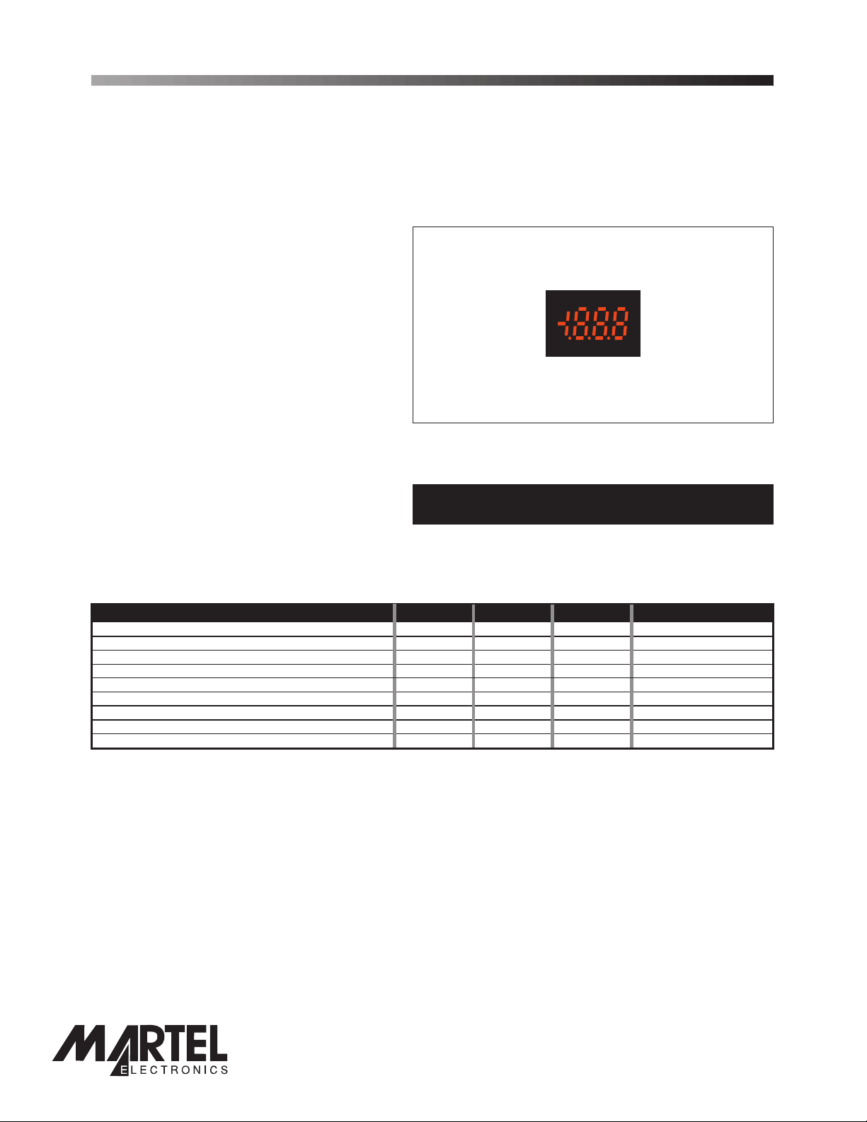
This low cost sub-miniature LED voltmeter module is ideally suited for high volume applications. It features an exceptionally
large display in a miniature package and includes auto-zero and user-selectable decimal points. The use of low current
display technology means this LED product can be considered for battery powered applications. The OEM 1B-LED is
dimensionally compatiblewith its LCD counterpart, the OEM 1B. Connection to the module is via two rows of pins.
FEATURES
•8
mm (0.31") Digit Height
• 200mV d.c. Full Scale Reading
• 50mA (typ) @ +5V d.c. Power Supply
•
Auto-zero and Auto-polarity
• User Selectable
• DIL Pin Connection
• Size compatible with OEM 1B (LCD module)
Decimal Points
Module shown actual size
TYPICAL APPLICATIONS
• High Volume, Low Cost Systems
• Power Supply Monitoring
ORDERING INFORMATION
Stock Number
Standard Meter OEM1B - LED
• Handheld Indication
• Panel-Mount Indication
ELECTRICAL SPECIFICATIONS
Specification Min. Typ. Max. Unit
Accuracy (overall error) * 0.05 0.1 % (±1 count)
Linearity ±1 count
Sample rate 2.5 samples/sec
Operating temperature range 0 50 °C
Temperature stability 150 ppm/°C
Warm-up time 10 minutes
Supply voltage 4.75 5 5.25 V d.c.
Supply current ** 50 100 mA
Input leakage current 1 10 pA
* To ensure maximum accuracy, re-calibrate periodically.
** Depends on reading and temperature.
Unless otherwise noted, specifications apply at T =25°C, V =5Vd.c. (f =40kHz) and are tested with the module configured for floating input
mode.
A supply clock
SAFETY
To comply with the Low Voltage Directive (LVD 93/68/EEC), input voltages to the module’s pins must not exceed
60Vdc. The usermustensurethat the incorporation of the panel meter into the user’s equipment conforms to the
relevant sections of BS EN 61010 (Safety Requirements for Electrical Equipment for Measuring, Control and
Laboratory Use).
LASCAR ELECTRONICS LTD.
MODULE HOUSE
WHITEPARISH
WILTSHIRE SP5 2SJ
UK
TEL: +44 (1794) 884567
FAX: +44 (1794) 884616
E-mail: sales@lascar.co.uk
LASCAR ELECTRONICS INC.
3750 West 26th Street
Erie
PA 16506
USA
TEL: +1 (814) 835 0621
FAX: +1 (814) 838 8141
E-mail: us-sales@lascarelectronics.com
PO Box 770, Londonderry, NH 03053 1-800-821-0023
www.martelcorp.com
www.lascarelectronics.com
LASCAR ELECTRONICS (HK) LIMITED
FLAT C, 5/FL., LUCKY FTY. BLDG.
63-65 HUNG TO ROAD
KWUN TONG KOWLOON
HONG KONG
TEL: +852 2797 3219
FAX: +852 2343 6187
E-mail: b4lascar@samsongroup.com.hk
Page1of4
Page 2

Page 2 of 4
OEM 1B-LED
DIMENSIONS
All dimensions in mm (inches)
3½ Digit LED Voltmeter Module
8.0
Viewing Area
(0.31)
23.4 (0.92)
19.5 (0.77)
Viewing Area
16.4 (0.65)
5.4 (0.21)
5.5 (0.22)
6.35
(0.25)
5.5
(0.22)
1.27 (0.05)
CAL
12.7 (0.50)
2.54 (0.10)5.0 (0.20)
FUNCTIONAL BLOCK DIAGRAM
V+
RHI
Vref
COM
RLO
IHI
ILO
+
CAL
0V
A/D
1
DP321
_
TEST
8
PO Box 770, Londonderry, NH 03053 1-800-821-0023
www.lascarelectronics.com
www.martelcorp.com
PIN CONFIGURATION
CAL
7
6
RHI
RLO
NC
COM
DP1
ILO
DP2
IHI
DP3
V+
(rear view)
12
TEST
0V
1
Page2of4
Pin 1
identifier
Page2of4
Page 3

OEM 1B-LED
OEM 1B-LED
CIRCUIT DIAGRAM
V+
2
IHI
3
ILO
4
5
COM
RHI
7
6
RLO
1
0V
3½ Digit LED Voltmeter Module
3½ Digit LED Voltmeter Module
DP1
9
DISPLAY
(199.9)
DP2
(19.99)
DP3
(1.999)
NC
TEST
10
11
8
NC
12
CERMET
0
PIN FUNCTIONS
1. 0V Negative power supply to the meter.
2. V+ Positive power supply to the meter.
3. IHI Positivemeasuring input.
IHI must be no closer than 1.5V to either the positive or negative supply (see Note).
4. ILO Negative measuring input.
ILO must be no closer than 1.5V to the positive supply (see Note).
5. COM
6. RLO Negative input for the reference voltage.
7. RHI Positive input for the reference voltage.
8. NC Not connected.
9. DP1 Connect to 0V to display DP1 (199.9).
10. DP2 Connect to 0V to display DP2 (19.99).
11. DP3 Connect to 0V to display DP3 (1.999).
12. TEST Connect to V+ to display all segments, except the decimal points.
Ground for the analogue section of the A/D converter. It is actively held at 3.05V (nom.) below
V+ and must not be allowed to sink excessivecurrent (>100 A) by,for instance, connecting
µ
to a higher voltage.
Note:
A negative supply is generated internally and mirrors the positive supply. For example: if V+ is +5V, then
the internally generated V- is -5V. When measuring with the input referenced to the same supply rail as
that of the panel meter, then the limitations on the input range are (V- + 1.5V) to (V+ - 1.5V).
PO Box 770, Londonderry, NH 03053 1-800-821-0023
www.lascarelectronics.com
Page3of4
www.martelcorp.com
Page 4
Page 4 of 4
OEM 1B-LED
3½ Digit LED Voltmeter Module
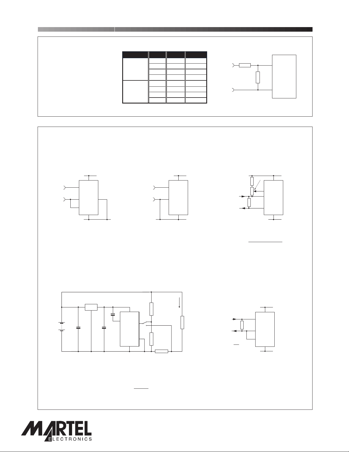
EXTERNAL SCALING
Two external resistors Ra and
Rb may be used to alter the
full scale reading (FSR) of the
meter - see table. The meter
will have to be re-calibrated
by adjusting the calibration
potentiometer on the rear of
the module.
Voltage
Vin 200V 1M 1k
Current
Iin 20mA 0R 10R
*Ensure that Ra is rated for high voltage use.
FSR Ra Rb
2V 910k 100k
20V 1M 10k
2000V* 1M 100R
200 A 0R 1k
µ
2mA 0R 100R
200mA 0R 1R
+
Vin or inI
-
Ra
Rb
IHI
OEM 1B-LED
ILO
APPLICATIONS
Do not connect more than one meter to the same power supply if the meters cannot use the same signal
ground. Taking any input beyond the power supply rails will damage the meter.
+4.75 to +5.25V +4.75 to +5.25V
2
V+
3
+
±200mV
-
IHI
49
DP1
ILO
5
COM
0V
1
0V
Measuring an input voltage referenced
to a floating supply, i.e. the input
voltage and the meter's power supply
are isolated from each other.
Circuit shows DP1 enabled.
7805
V
supply
220nF 470nF
+5V
10uF
5
COM
V+
0V
2
IHI
ILO
1
Measuring supply voltage and current to a load.
S selectsbetween voltage and current measurement.
1
2
V+
3
+
±200mV
-
IHI
4
ILO
0V
1
0V
Measuring a single ended input
voltage referenced to supply, i.e. the
input voltage and the meter's power
supply share the same 0V rail.
I
Ra=1M
V
3
S
1
A
4
Rb=1k
Rs
Shunt
Load
R
L
Set Zero
220k
4
5k
4-20mA
current loop
I
+
R
I-
5
3
Measuring a 4-20mA loop current.
R= Reading at 20mA
160
The meter's power supply must be
isolated from the 4-20mA current
loop.
V+
3
4
5
IHI
ILO
COM
0V
R = 0.2
R
I
FSR
Measuring current.
The meter's supply is isolated
from the current being measured.
2
V+
ILO
COM
IHI
0V
1
+4.75 to +5.25V
2
1
0V
+4.75 to +5.25V
0V
Ra and Rb shown scaled for 200V
FSR
Rs = 200mV
I
(e.g. 0.1 / 400mW for 2A full scale)Ω
FSR
Display DP1, DP2 or DP3, by connecting to 0V,as required.
Specifications liable to change without prior warning OEM 1B-LED Issue 2 September/2002 M.C. Applies to OEM 1B-LED/1
Page4of4
PO Box 770, Londonderry, NH 03053 1-800-821-0023
www.lascarelectronics.com
Page4of4
www.martelcorp.com
 Loading...