

Page 1
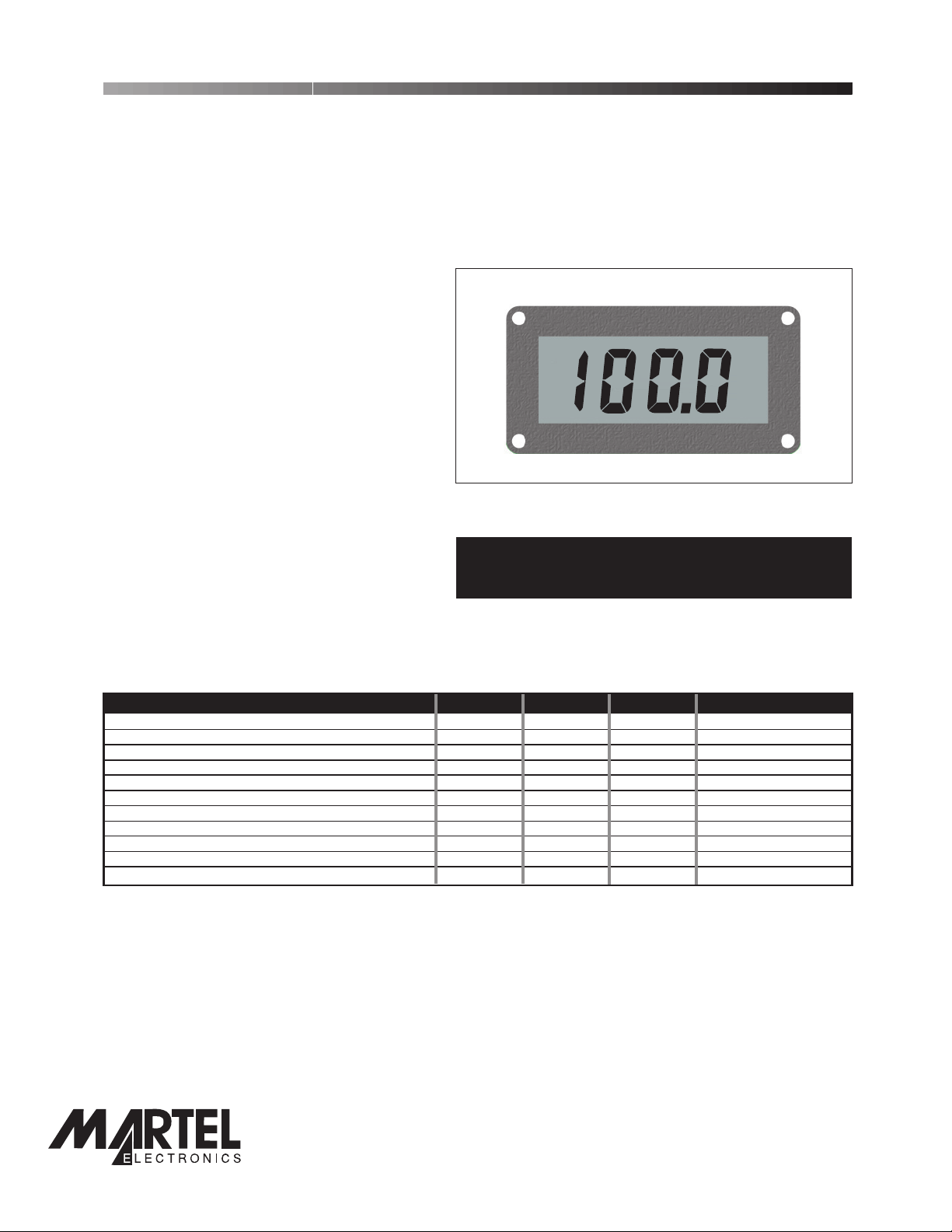
DPM 742-BL
Page 2 of 4
4-20mA Loop Powered Indicator with Backlighting
PRODUCT DESCRIPTION
The DPM 742-BL gives an accurate, zero adjusted indication of a 4-20mA current. Calibration is by two multi-turn
potentiometers which allow sensitive adjustment of the instrument over a very wide range. Decimal points are jumper
link selectable. LED
A low drift bandgap reference circuit ensures accurate readings over a wide temperature range.
backlighting ensures excellent readability under low light conditions. Connection is via screw terminals. The module's
low cost means it will suit high and low volume applications. This module is supplied with a plastic mounting bezel. A
waterproof seal to IP67 / NEMA 4X is achievable, using the optional BEZ 700-IP metal bezel.
FEATURES
• 12.7
mm (0.5") Digit Height
• 4-20mA Loop Powered Indication
• Low Volt Drop
•
Programmable Decimal Points
•
LED Backlighting (30mA @ 5V typ.)
• Bandgap Reference
• Wide Adjustment Range
• Auto-polarity on Display
• IP67 / NEMA 4X Protection via BEZ 700-IP
ORDERING INFORMATION
Stock Number
Standard Meter DPM 742-BL
IP67 / NEMA 4X Bezel BEZ 700-IP
ELECTRICAL SPECIFICATIONS
Specification Min. Typ. Max. Unit
Accuracy (overall error) * 0.05 0.1 % (±1 count)
Linearity ±1 count
Sample rate 2.5 samples/sec
Operating temperature range 0 50 °C
Temperature stability 200 ppm/°C
Loop Volt Drop 5 5.6 V
Supply current 4 20 mA
Backlight supply voltage 4.75 5.0 ** V d.c.
Backlight supply current @ 5V d.c. 30 50*** mA
Full scale reading (@20mA) 0 1999 Count
Offset adjustment range -1900 +1900 Count
* To ensure maximum accuracy, re-calibrate periodically.
** An external series resistor is required above 5V, see Applications.
*** This specification linearly derates to 30mA @ 50°C.
LASCAR ELECTRONICS LTD.
MODULE HOUSE
WHITEPARISH
WILTSHIRE SP5 2SJ
UK
TEL: +44 (1794) 884567
FAX: +44 (1794) 884616
E-mail: sales@lascar.co.uk
LASCAR ELECTRONICS INC.
3750 West 26th Street
Erie
PA 16506
USA
TEL: +1 (814) 835 0621
PO Box 770, Londonderry, NH 03053 1-800-821-0023
FAX: +1 (814) 838 8141
E-mail: us-sales@lascarelectronics.com
www.martelcorp.com
www.lascarelectronics.com
LASCAR ELECTRONICS (HK) LIMITED
FLAT C, 5/FL., LUCKY FTY. BLDG.
63-65 HUNG TO ROAD
KWUN TONG KOWLOON
HONG KONG
TEL: +852 2797 3219
FAX: +852 2343 6187
E-mail: b4lascar@samsongroup.com.hk
Page2of4
Page1of4
Page 2
Page 2 of 4
DPM 742-BL
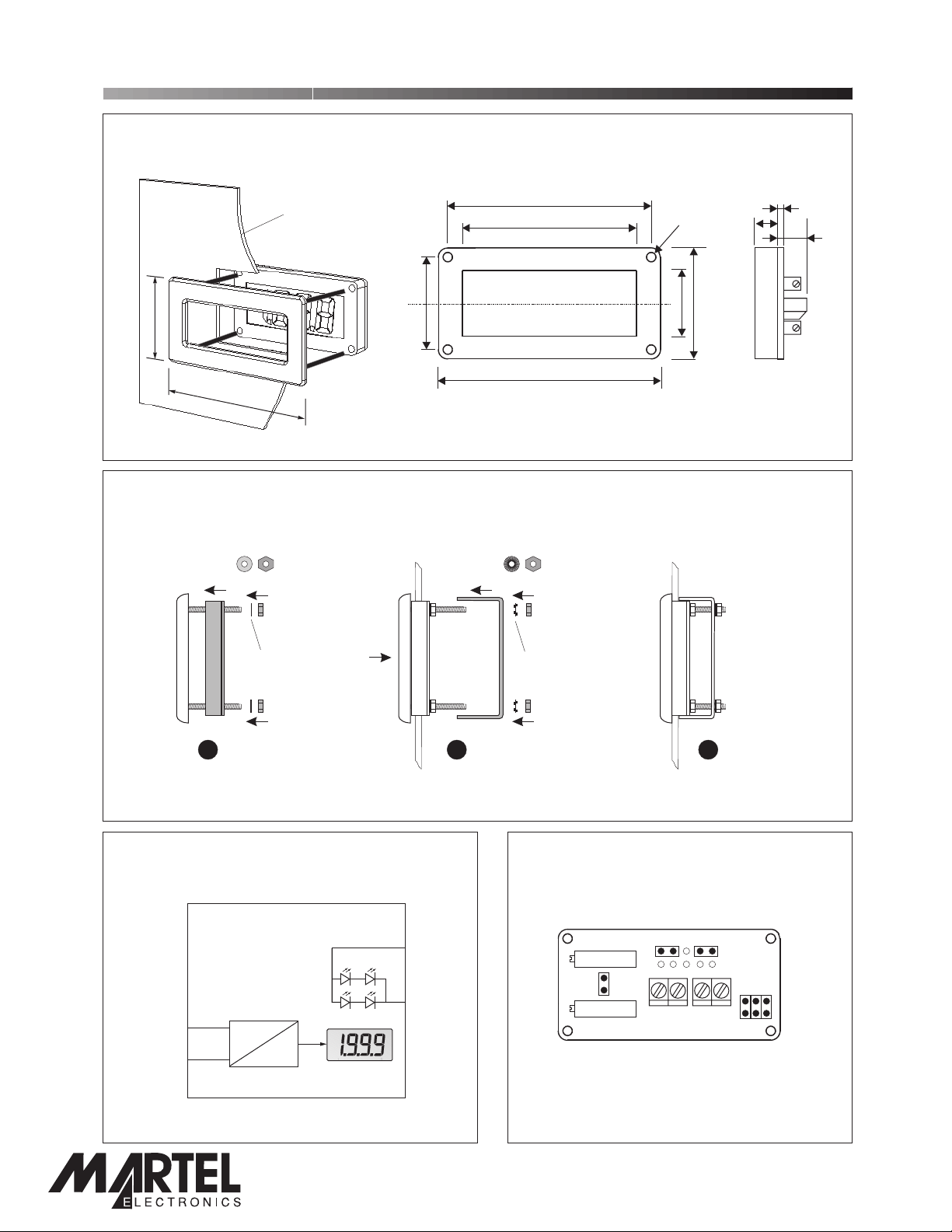
DIMENSIONS
All dimensions in mm (inches)
4-20mA Loop Powered Indicator with Backlighting
34.5 (1.36)
64.5 (2.54)
Panel cut-out: 62.0 - 32.0
(2.44 - 1.26)
PANEL FITTING
Panel thickness: 1.0 - 3.0
(0.04 - 0.12)
25.0 (0.98)
53.0 (2.17)
46.7 (1.84)
60 (2.36)
2.8 (0.11) dia
30 (1.18)
17.7 (0.7)
1.6 (0.06)
6.1 (0.24)
13.0
(0.51)
Insulating
Washer
FUNCTIONAL BLOCK DIAGRAM
BL+
BL-
I+
I-
4-20mA
Vdc
8
1
Shake-proof
Washer
21
CONNECTIONS
3
(rear view)
JA JB
Offset
DP
321
Span
Lk1
I+ I- BL+ BL-
PO Box 770, Londonderry, NH 03053 1-800-821-0023
www.lascarelectronics.com
www.martelcorp.com
Page2of4
Page2of4
Page 3

DPM 742-BL
CIRCUIT DIAGRAM
4-20mA Loop Powered Indicator with Backlighting
SCREW TERMINAL FUNCTIONS
I+ Positivecurrent input.
I- Negative current input.
BL+ Positivepower supply connection to the LED backlighting.
BL- Negativepower supply connection to the LED backlighting .
CALIBRATION
The meter is supplied calibrated to read 000 for 4mA loop current and 1000 for 20mA.
To re-calibrate, place the Jumper Link across LK1. This disables the Offset adjustment to enable Span adjustment to be made first. After
Span adjustment is complete, the Jumper Link is removed and the Offset adjustment is made. The Jumper Link is then used to display one
of the decimal points if necessary.
Example to re-calibrate: Meter to read -40.0 at 4mA and 150.0 at 20mA.
1. Calculatethe Span by subtracting the desired reading at 4mA from the desired reading at 20mA: 1500- (-400)= 1900
2. PlaceJumper Link Lk1 with the link header normally used to select the desired Decimal Point.
Link Lk1 is located to the left of the screw terminals.
3. Apply16mA between the + and - screw terminals.
4. Adjustthe Span potentiometer so the DPM 742-BL indicates 1900.
5. RemoveJumper Link Lk1 and place it back on the desired Decimal Point (DP1 in this case).
6. Apply4mA between the - and + screw terminals.
7. Adjustthe Offset potentiometer so the DPM 742-BL indicates the desired reading at 4mA: -40.0
8. AdjustSpan and Offset as necessary for optimum accuracy.First apply 20mA and adjust Span untill
the reading is 150.0. Then apply 4mA and adjust Offset untill the reading is -40.0.
Repeat step 8 until correct readings are obtained at 4mA and at 20mA.
Offset
Span
PO Box 770, Londonderry, NH 03053 1-800-821-0023
www.lascarelectronics.com
Page3of4
www.martelcorp.com
Page 4

Page 4 of 4
DPM 742-BL
JUMPER LINKS
DP1 Displays decimal point DP1 (199.9).
DP2 Displays decimal point DP2 (19.99).
DP3 Displays decimal point DP3 (1.999).
Lk1 Usedduring calibration (see above).
4-20mA Loop Powered Indicator with Backlighting
321
DP
DP
321
DP
321
APPLICATIONS
The DPM 750-BL is powered from the 4-20mA signal loop and needs no other power supply. The LED backlighting requires a
separate d.c. power supply. Ensure correct polarity when connecting.
Other
Device
1
I+ I+
4-20mA
Transmitter
Measuring a 4-20mA loop current.
4-20mA
Transmitter
Measuring a 4-20mA loop current with LED
Backlighting switched on.
I- I-
I+
I-
I+
DPM 742-BL
I-
I+ BL+
DPM 742-BL
I- BL-
I+
4-20mA
Transmitter
Other
Device
2
Measuring a 4-20mA loop current
with other devices in the loop.
V+
S
BL
R
R=
V+-5V
30mA
0V
DPM 742-BL
I-
Note:
If the backlighting supply voltage (V+ - 0V) = 5V,
then no resistor R is required, and connect BL- to 0V.
Specifications liable to change without prior warning DPM 742-BL Issue 1 August/2002 M.C. Applies to DPM 742-BL/1
PO Box 770, Londonderry, NH 03053 1-800-821-0023
www.lascarelectronics.com
www.martelcorp.com
Page4of4
Page4of4
 Loading...