

Page 1
Technical Specifications Bulletin
1
Page 2

General Features
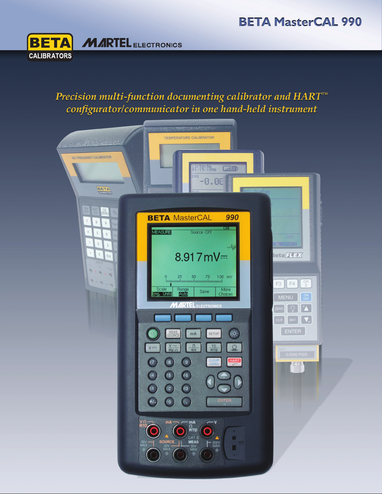
• Precision multi-function calibrator and
HART™ configurator/communicator in one
hand-held instrument
• Measure/read thermocouple, RTD, Ohms,
DC and AC Voltage, DC current, pressure,
and frequency
• Source/simulate thermocouple, RTD, Ohms,
DC Voltage and current, pressure, and
frequency
• Simultaneous input and output split-screen
displays
• Loop power function
• Switch testing functions
• Transmitter mode
• Automated and user-programmable procedures
• Engineering units, percent of scale, square-
law inputs, or custom units
• Multi-lingual interface – English, French,
German, Italian, and Spanish
• 200x240 pixel, bright white, backlit LCD
display
• Rugged over-molded urethane case for field
use
• Calibration automation and documentation
with many popular third-party software
packages
• Complies with CAN/CSA C22.2 No 1010.1-92,
ANSI/ISA S82.01-1994, UL3111, and EN6101:1993
HART Protocol Features
• Universal, common practice and device-
specific commands
• Point-to-point and multi-drop operation
• Burst mode compatibility
• Read HART PV in digital mode
• Read and write HART configuration func-
tions
• Read and clone transmitter configuration
• Re-tag smart transmitters
• Automated HART sensor and output trim
The MasterCAL 990 - A Precision
Multi-Function Documenting
Calibrator
First and foremost, the MasterCAL 990 is a
precision, multi-function documenting
calibrator that will calibrate virtually any
process instrument you have –
thermocouples, RTDs, Ohms, Voltage,
current, pressure, and frequency. A host of
convenience features, including source ramp
functions, loop power, variable density data
logging with a week’s worth of calibration
results storage, compatibility with many
third-party calibration documentation
software programs, and a built-in HART
configuration/communicator, make the
MasterCAL 990 an indispensable tool.
A large, white backlit LCD provides
simultaneous display of input and output.
Menu-driven, “soft” function keys provide
rapid setup and measurement. The multilingual interface ensures the MasterCAL 990
is useful in as broad a range of applications
and locations as possible. A high capacity
rechargeable battery pack provides extended
usage. An optional battery eliminator is
available for extended monitoring
applications. The MasterCAL 990 is housed
in an over-molded urethane case that
provides a solid grip and protection against
“hard knocks”.
Source/Simulation
The MasterCAL 990 will source/simulate
thermocouple, RTD, Ohms, DC Voltage and
current, and frequency. Auto-step and ramp
functions are provided on all outputs and
ranges.
2
Page 3

Measurement/Read
The MasterCAL 990 will measure/read
thermocouple, RTD, Ohms, DC and AC
Voltage, DC current, pressure, and frequency.
Measuring pressure requires the use of the
Beta Pressure Module Adapter (Model
BPPA100) with any of Beta’s Pressure
Modules (please refer to the separate
Pressure Module data sheet for ranges and
accuracies).
Switch Test Mode
Process limit switches can be tested for both
upper and lower trip limits and deadband.
Using a split-screen measure/source mode,
the MasterCAL 990 accepts a normal process
variable measurement associated with the
limit switch, and the switch contacts. The 990
will automatically monitor and record the
measurement as the switch is activated and
then deactivated. A graphical plot of
deadband is displayed, making switch test
quick and accurate.
Built-In Calculator Functions
The MasterCAL 990 features a built-in
calculator with square-root function, with
accessible registers containing measure and
source values.
Barcode Entry Option
The MasterCAL 990 will accept input from an
optional barcode wand for rapid entry of
instrument serial numbers.
Simultaneous Measure/Source
Using a split-screen display mode,
the MasterCAL 990 will
simultaneously measure and source
various process variables. These
variables depend on whether loop
power is enabled or disabled. Please
refer to Table 1.
Transmitter Mode
The MasterCAL 990 can be inserted
in a 4-20 mA process loop to simulate
a 2-wire transmitter. The MasterCAL
990 provides the loop excitation and
modulates the loop current,
simulating the 2-wire transmitter.
Table 1 – Simultaneous Measure/Source
3
Page 4

The MasterCAL 990 - A HART Configurator/Communicator
HART Implementation
The MasterCAL 990 supports HART Version
5.7 protocol instructions. It’s functions are
comparable to a HART 275 Communicator;
because the MasterCAL 990 does not have a
DD interpreter, it does not support DD
libraries. Most instrument maintenance
functions can be accomplished using just the
MasterCAL 990 without the need for a
separate HART communicator. Hookup is
simple with the supplied HART interface
cable. The calibrator menus automatically
branch to appropriate adjustment choices.
Automatic completion of test templates and
automatic fetching and sending of analog
readings during trim operations make HART
calibration a highly efficient operation.
Protocol Instructions
The MasterCAL 990 instruction set includes
three levels of commands:
Universal Commands – provides functions for
all field instruments to read manufacturer and
device type, primary variable/input signal (PV),
read output, tag ID, etc.
Operating Modes
The MasterCAL 990 supports HART
Point-to-Point Operation, where a single
HART instrument is connected in a loop; the
calibrator is normally connected directly at the
instrument’s local signal terminals. The
MasterCAL 990 is also compatible with
multi-drop and burst mode HART
installations.
Documenting Calibration
The MasterCAL 990 is compatible with many
third-party calibration documentation
software programs including:
• Applied Systems Technologies Cal Station
and Base Station
• Emerson Process Management AMS
• Prime Technologies ProCal
• Fluke DPC Track
• Honeywell DocuMint
• Others supporting the ISA Field Calibrator
Interface standard
Common Practice Commands – provides
functions that are common to most field
instruments, such as reading multiple
variables, setting damping features, etc.
Device-Specific Commands – allows the
MasterCAL 990 to perform device-specific
configuration functions for a wide variety of
popular field instruments. Please refer to
Table 2.
4
Page 5

Table 2 – Device Specific Configuration Functions
Manufacturer Pressure Instruments Temperature Instruments
ABB/Kent-Taylor 600T 658T
ABB/Hartmann & Braun Contrans P 1, AS 800 Series
Endress & Hauser CERABAR S, TMT 122 1, TMT 182 1,
CERABAR M, TMT 162
DELTABAR S
Foxboro Eckardt T1/RTT20
Foxboro/Invensys I/A Pressure
Honeywell ST3000 STT25T 1, STT25H
Moore Products 344
1
Rosemount 1151 3044C
2088 644
3001C 3144
3051, 3051S 3244, 3144P
Siemens SITRANS P DS
SITRANS P ES
SMAR LD301 TT301
Viatran I/A Pressure
Wika UNITRANS T32H
Yokogawa EJA YTA 110, 310, and 320
1 Sensor Trim not supported
1
1
1
1
1
1
5
Page 6

Specifications (18 °C to 28 °C unless otherwise noted)
DC Voltage Read and Source
Measurement Range/Accuracy
(% of reading + % of full scale; 1 year; 2 year)
0.000 to 110.000 mV ±0.025% rdg.
+0.015%FS
±0.05% rdg. +0.015%FS
0.000 to 1.10000 V ±0.025% rdg.
+0.005%FS
±0.05% rdg. +0.005%FS
0.000 to 11.0000 V ±0.025% rdg.
+0.005%FS
±0.05% rdg. +0.005%FS
0.000 to 110.000 V ±0.025% rdg.
+0.005%FS
±0.1% rdg. +0.005%FS
0.000 to 300.00 V ±0.05% rdg. +0.005%FS
±0.1% rdg. +0.005%FS
Read Input Impedance 5 MOhms
Read Common Mode Error ±0.008% FS/V
Read Input Voltage 300 V rms maximum
Temperature Coefficient (±0.001% rdg +
0.0015% FS)/°C;
-10 °C to 18 °C, and 28°C
to 50 °C
Source Range/Accuracy
(% of reading + % of full scale; 1 year; 2 year)
0.000 to 110.000 mV ±0.01% rdg. +0.005%FS
±0.015% rdg.
+0.005%FS
0.000 to 1.10000 V ±0.01% rdg. +0.005%FS
±0.015% rdg.
+0.005%FS
0.000 to 15.0000 V ±0.01% rdg. +0.005%FS
±0.015% rdg.
+0.005%FS
Source Output Loading (±0.001% FS + 1 µV)/mA
Source Common Mode Error 0.008% FS/V
Source Output Current 10 mA maximum
Source Output Voltage 30 VDC maximum
Temperature Coefficient (±0.001% rdg + 0.001%
FS)/°C; -10 °C to 18 °C,
and 28 °C to 50 °C
COMMON-MODE
COMMON-MODE
AC Voltage Read (10% to 100% of range)
Measurement Range/Accuracy
(% of reading + counts; 1 year; 2 year)
20 to 40 Hz ±2% rdg. +10
±2% rdg. +10
40 to 500 Hz ±0.5% rdg. +5
±0.5% rdg. +5
500 Hz to 1 kHz ±2% rdg. +10
±2% rdg. +10
1 to 5 kHz ±10% rdg. +20
±10% rdg. +20
Read Input Voltage
Minimum 0.5 V above 1 kHz
Ranges 1.1000 V, 11.000 V,
110.00 V, 300.0 V
Maximum 300 V rms
Read Input Impedance 5 MOhms and <100 pF
Read Input Coupling AC only
Read Common Mode Error ±0.008% FS/V
COMMON-MODE
Temperature Coefficient ±10% of spec/°C;
-10 °C to 18 °C, and 28°C
to 50 °C
DC Current Read and Source
Measurement Range/Accuracy
(% of output + % of full scale; 1 year; 2 year)
0.000 to 30.000 mA ±0.01% +0.015%FS
±0.02% +0.015%FS
0.000 to 110.000 mA ±0.01% +0.015%FS
±0.02% +0.015%FS
Read Common Mode Error ±0.01% FS/V
Read Input Voltage 30 VDC maximum
Temperature Coefficient (±0.001% rdg + 0.002%
FS)/°C;
-10 °C to 18 °C, and 28°C
to 50 °C
Source Range/Accuracy
(% of output + % of full scale; 1 year; 2 year)
0.000 to 22.000 mA ±0.01% +0.015%FS
±0.02% +0.015%FS
Transmitter simulate ±0.02% rdg. +0.005%FS
(current sink) ±0.015% rdg. +0.005%FS
Source Burden Voltage 24 V maximum
Source Common Mode Error 0.008% FS/V
Source Input Voltage 30 VDC maximum
Temperature Coefficient (±0.003% output +
0.003% FS)/°C;
-10 °C to 18 °C, and 28°C
to 50 °C
COMMON-MODE
COMMON-MODE
6
Page 7

Ohms Read and Source
Measurement Range/Accuracy
(% of reading + Ohms; 1 year; 2 year)
0.000 to 11.000 Ohms ±0.05% + 50 mΩ
±0.075% + 50 mΩ
0.000 to 110.00 Ohms ±0.05% + 50 mΩ
±0.075% + 50 mΩ
0.000 to 1.1000 kOhms ±0.05% + 0.5 Ω
±0.075% + 0.5 Ω
0.000 to 11.000 kOhms ±0.1% + 10 Ω
±0.1% + 10 Ω
Read Common Mode Error ±0.005% FS/V
Read Input Voltage 30 VDC maximum
Continuity continuous tone <<25 Ω;
no tone >400 Ω
Temperature Coefficient (±0.01% FS + 2 mΩ)/°C;
-10 °C to 18 °C, and 28°C
to 50 °C
Source Range/Accuracy
(% of output + Ohms; 1 year; 2 year)
0.000 to 11.000 Ohms ±0.01% + 20 mΩ
±0.02% + 20 mΩ
0.000 to 110.00 Ohms ±0.01% + 40 mΩ
±0.02% + 40 mΩ
0.000 to 1.1000 kOhms ±0.02% + 0.5 Ω
±0.03% + 0.5 Ω
0.000 to 11.000 kOhms ±0.03% + 5 Ω
±0.04% + 5 Ω
Read Common Mode Error ±0.008% FS/V
Source Input Voltage 30 VDC maximum
Current Through Source Resistance
11.000 Ohms range 3 mA DC max.; 0.1 mA DC min.
11.000 Ohms range 3 mA DC max.; 0.1 mA DC min.
11.000 Ohms range 3 mA DC max.; 0.01 mA DC min.
11.000 Ohms range 1 mA DC max.; 0.01 mA DC min.
Temperature Coefficient ±0.01% FS/°C;
-10 °C to 18 °C, and 28 °C
to 50 °C
COMMON-MODE
COMMON-MODE
Frequency Read and Source
(For frequencies <109.99 Hz, specification applies for
signals with slew rates >5 V/ms)
Measurement Range/Accuracy (1 year; 2 year)
1.00 to 109.99 Hz ±0.05 Hz
±0.05 Hz
110.0 to 1099.9 Hz ±0.5 Hz
±0.5 Hz
1.100 to 10.999 kHz ±0.005 Hz
±0.005 Hz
11.00 to 50.00 kHz ±0.05 kHz
±0.05 kHz
Minimum Input Amplitudes
1 Hz to 1 kHz squarewave 300 mVP-P
1 kHz to 30 kHz squarewave 1.4 VP-P
>30 kHz 2.8 VP-P
Maximum Input Amplitudes
1 Hz to 1 kHz 300 V rms
>1 kHz 30 V rms
Input Impedance 5 MOhms
Source Range/Accuracy
(1 year; 2 year)
0.00 to 10.99 Hz ±0.01 Hz
±0.01 Hz
11.00 to 109.99 Hz ±0.1 Hz
±0.1 Hz
110.0 to 1099.9 Hz ±0.1 Hz
±0.1 Hz
1.100 to 21.999 kHz ±0.002 kHz
±0.002 kHz
22.00 to 50.00 kHz ±0.005 kHz
±0.005 kHz
Waveforms squarewave with 50%
duty cycle sinewave
Amplitude 0.1 to 10 VP-P;
user-adjustable
Amplitude Accuracy
1 to 1099 Hz ±3% of output + 0.5% FS
1.1 to 10. 9 kHz ±10% of output + 0.5% FS
11 to 50 kHz ±30% of output + 0.5% FS
Input Voltage 30 VDC maximum
7
Page 8

Thermocouple Read and Source
(Accuracies with external cold junction; add 0.2 °C for
internal junction; sensor inaccuracies not included)
Resolution 0.1 °C
Temperature Scale ITS-90 or IPTS-68, selectable
Compensation ITS-90 per Monograph 175
for E/N/J/K/T/B/R/S thermcouples
IPTS-68 per IEC 584-1 for
E/J/K/T/B/R/S thermcouples
IPTS-68 per DIN 43710 for L and U
thermocouples
Input Voltage 30 VDC maximum
Common Mode Error 0.01 °C/V
Temperature Coefficient 0.05 ¨C/°C;
-10 °C to 18 °C, and 28 °C to
50 °C
Read Type/Range/Accuracy (1 year; 2 year)
J Thermocouple
-210 to -100 °C ±0.6 °C; ±0.9 °C
-100 to +800 °C ±0.3 °C; ±0.4 °C
+800 to +1200 °C ±0.5 °C; ±0.8 °C
K Thermocouple
-210 to -100 °C ±0.7 °C; ±1.0 °C
-100 to +400 °C ±0.3 °C; ±0.4 °C
+400 to +1200 °C ±0.5 °C; ±0.8 °C
+1200 to +1372 °C ±0.7 °C; ±1.0 °C
T Thermocouple
-250 to -200 °C ±1.7 °C; ±2.5 °C
-200 to 0 °C ±0.6 °C; ±0.9 °C
0 to +400 °C ±0.3 °C; ±0.4 °C
E Thermocouple
-250 to -200 °C ±1.3 °C; ±2.0 °C
-200 to -100 °C ±0.5 °C; ±0.8 °C
-100 to +600 °C ±0.3 °C; ±0.4 °C
+600 to +1000 °C ±0.4 °C; ±0.6 °C
R Thermocouple
-20 to 0 °C ±2.3 °C; ±2.8 °C
0 to +100 °C ±1.5 °C; ±2.2 °C
+100 to +1767 °C ±1.0 °C; ±1.5 °C
S Thermocouple
-20 to 0 °C ±2.3 °C; ±2.8 °C
0 to +200 °C ±1.5 °C; ±2.1 °C
+200 to +1400 °C ±0.9 °C; ±1.4 °C
+1400 to +1767 °C ±1.1 °C; ±1.7 °C
B Thermocouple
+600 to +800 °C ±1.3 °C; ±2.0 °C
+800 to +1000 °C ±1.0 °C; ±1.5 °C
+1000 to +1820 °C ±0.9 °C; ±1.3 °C
COMMON-MODE
C Thermocouple
0 to +800 °C ±0.6 °C; ±0.9 °C
+800 to +1200 °C ±0.8 °C; ±1.2 °C
+1200 to +1800 °C ±1.1 °C; ±1.6 °C
+1800 to +2316 °C ±2.0 °C; ±3.0 °C
L Thermocouple
-200 to -100 °C ±0.6 °C; ±0.9 °C
-100 to +800 °C ±0.3 °C; ±0.4 °C
+800 to +900 °C ±0.5 °C; ±0.8 °C
U Thermocouple
-200 to 0 °C ±0.6 °C; ±0.9 °C
0 to +600 °C ±0.3 °C; ±0.4 °C
N Thermocouple
-200 to -100 °C ±1.0 °C; ±1.5 °C
-100 to +900 °C ±0.5 °C; ±0.8 °C
+900 to +1300 °C ±0.6 °C; ±0.9 °C
Source Type/Range/Accuracy (1 year; 2 year)
J Thermocouple
-210 to -100 °C ±0.3 °C; ±0.4 °C
-100 to +800 °C ±0.2 °C; ±0.3 °C
+800 to +1200 °C ±0.2 °C; ±0.3 °C
K Thermocouple
-210 to -100 °C ±0.4 °C; ±0.6 °C
-100 to +400 °C ±0.3 °C; ±0.4 °C
+400 to +1200 °C ±0.3 °C; ±0.4 °C
+1200 to +1372 °C ±0.3 °C; ±0.4 °C
T Thermocouple
-250 to -200 °C ±0.9 °C; ±1.4 °C
-200 to 0 °C ±0.4 °C; ±0.9 °C
0 to +400 °C ±0.3 °C; ±0.4 °C
E Thermocouple
-250 to -200 °C ±0.6 °C; ±0.9 °C
-200 to -100 °C ±0.3 °C; ±0.4 °C
-100 to +600 °C ±0.3 °C; ±0.4 °C
+600 to +1000 °C ±0.2 °C; ±0.3 °C
R Thermocouple
-20 to 0 °C ±1.2 °C; ±1.8 °C
0 to +100 °C ±1.1 °C; ±1.7 °C
+100 to +1767 °C ±0.9 °C; ±1.4 °C
S Thermocouple
-20 to 0 °C ±1.2 °C; ±1.8 °C
0 to +200 °C ±1.1 °C; ±1.7 °C
+200 to +1400 °C ±0.9 °C; ±1.4 °C
+1400 to +1767 °C ±1.0 °C; ±1.5 °C
8
Page 9

B Thermocouple
+600 to +800 °C ±1.0 °C; ±1.5 °C
+800 to +1000 °C ±0.8 °C; ±1.2 °C
+1000 to +1820 °C ±0.8 °C; ±1.2 °C
C Thermocouple
0 to +800 °C ±0.6 °C; ±0.9 °C
+800 to +1200 °C ±0.7 °C; ±1.0 °C
+1200 to +1800 °C ±0.9 °C; ±1.4 °C
+1800 to +2316 °C ±1.3 °C; ±2.0 °C
L Thermocouple
-200 to -100 °C ±0.3 °C; ±0.4 °C
-100 to +800 °C ±0.2 °C; ±0.3 °C
+800 to +900 °C ±0.2 °C; ±0.3 °C
U Thermocouple
-200 to 0 °C ±0.4 °C; ±0.6 °C
0 to +600 °C ±0.3 °C; ±0.4 °C
N Thermocouple
-200 to -100 °C ±0.6 °C; ±0.9 °C
-100 to +900 °C ±0.5 °C; ±0.8 °C
+900 to +1300 °C ±0.3 °C; ±0.4 °C
Note: When simulating temperature in As Found/As Left
procedures, steps may be either linear by temperature or
linear by mV potential.
9
9
Page 10

RTD Read and Source
(For 2-wire or 3-wire measurements, add 0.4 °C;
sensor inaccuracies not included)
Resolution 0.1 °C, except 1 °C for
10 Ω Cu
Input Voltage 30 VDC maximum
Input Current for RTD Source Function
10, 100, 120 Ù RTDs 8 mA DC
200, 500, 1000 Ù RTDs 1 mA DC
addresses pulsed
transmitters and PLCs
with pulses as short
as 1 ms
Temperature Coefficient 0.02 °C/°C;
-10 °C to 18 °C, and 28°C
to 50 °C
Read Type/Range/Accuracy (1 year; 2 year)
Cu10
-100 to 0 °C ±2.0 °C; ±2.0 °C
0 to +260 °C ±2.0 °C; ±2.0 °C
Pt100 (3916)
-200 to -190 °C ±0.3 °C; ±0.4 °C
-190 to 0 °C ±0.3 °C; ±0.4 °C
0 to +630 °C ±0.5 °C; ±0.8 °C
Pt100 (3926)
-200 to 0 °C ±0.3 °C; ±0.4 °C
0 to +630 °C ±0.5 °C; ±0.8 °C
Pt100 (385)
-200 to 0 °C ±0.3 °C; ±0.5 °C
0 to +400 °C ±0.5 °C; ±0.8 °C
+400 to +800 °C ±0.8 °C; ±1.0 °C
Pt200 (385)
-200 to 0 °C ±0.3 °C; ±0.5 °C
0 to +400 °C ±0.5 °C; ±0.8 °C
+400 to +630 °C ±0.8 °C; ±1.0 °C
Pt500 (385)
-200 to 0 °C ±0.3 °C; ±0.5 °C
0 to +400 °C ±0.5 °C; ±0.8 °C
+400 to +630 °C ±0.8 °C; ±1.0 °C
Pt1000 (385)
-200 to 0 °C ±0.3 °C; ±0.5 °C
0 to +400 °C ±0.5 °C; ±0.8 °C
+400 to +630 °C ±0.8 °C; ±1.0 °C
Ni120 (672)
-80 to +260 °C ±0.3 °C; ±0.4 °C
Source Type/Range/Accuracy (1 year; 2 year)
Cu10
-100 to 0 °C ±1.0 °C; ±1.0 °C
0 to +260 °C ±1.0 °C; ±1.0 °C
Pt100 (3916)
-200 to -190 °C ±0.3 °C; ±0.4 °C
-190 to 0 °C ±0.1 °C; ±0.2 °C
0 to +630 °C ±0.2 °C; ±0.4 °C
Pt100 (3926)
-200 to 0 °C ±0.1 °C; ±0.2 °C
0 to +630 °C ±0.2 °C; ±0.4 °C
Pt100 (385)
-200 to 0 °C ±0.1 °C; ±0.2 °C
0 to +400 °C ±0.2 °C; ±0.4 °C
+400 to +800 °C ±0.4 °C; ±0.5 °C
Pt200 (385)
-200 to 0 °C ±0.1 °C; ±0.2 °C
0 to +400 °C ±0.2 °C; ±0.4 °C
+400 to +630 °C ±0.4 °C; ±0.5 °C
Pt500 (385)
-200 to 0 °C ±0.1 °C; ±0.2 °C
0 to +400 °C ±0.2 °C; ±0.4 °C
+400 to +630 °C ±0.4 °C; ±0.5 °C
Pt1000 (385)
-200 to 0 °C ±0.1 °C; ±0.2 °C
0 to +400 °C ±0.2 °C; ±0.4 °C
+400 to +630 °C ±0.4 °C; ±0.5 °C
Ni120 (672)
-80 to +260 °C ±0.1 °C; ±0.2 °C
Pressure Read and Source
Please refer to the Beta Pressure Module Data Sheet,
030606R0 for ranges and accuracies. Requires use of
included BPPA100 Pressure Module Adapter.
10
Page 11

General
Loop Power
Voltage 24 V or 28 V, selectable
Maximum Current: 22 mA, short-circuit protected
Input Voltage 30 VDC maximum
Accuracy 5%
Note: A 250Ù series resistance is automatically supplied whenever looppower is enabled.
Ramp Functions
Source Functions Voltage, current, Ohms, frequency, temperature
Rate 4 steps/second
Trip Detect continuity or voltage; continuity detection not availablewhen sourcing
current
Data Log Function
Measure Functions Voltage, current, Ohms, frequency, temperature, pressure
Reading Rate 1, 2, 5, 10, 20, 30, or 60 readings/minute
Maximum Record Length 8,000 readings 7,980 for 30 or 60 readings/minute
Environmental
Operating Temperature -20 °C to +50 °C
-10 °C to +50 °C for in spec frequency and AC read
Storage Temperature -20 °C to +60 °C
Altitude 9,186 ft (2800 m) above mean sea level
Stability (90 day) Typical 90-day measurement/read and source/simulate accuracy can be
estimated by dividing the one year “% of reading” or “% of output”
specifications by 2. Floor specifications, expressed as “% of FS” or
“counts” or “Ohms” remain constant
Power Requirements 7.2 VDC
Battery NiMH rechargeable, 3500 mAH; included
Battery Life >8 hours, typical usage
Physical
Dimensions 9.3"H x 5.1"W x 2.4"D
(236 x 130 x 61 mm)
Weight 3 lbs, 1 oz. (1.4 kg)
Connectors/Ports Pressure module connector
RS232 serial
External power in
Included Accessories Test lead set (4 leads, test clips, test probes)
NimMH battery pack
Battery pack charger
Deluxe carrying case
BPPA100 Pressure Module Adapter
Serial port cable
HART communications cable
NIST-traceable calibration certificate, with data
Multi-lingual instruction manual on CD
Warranty registration card
Optional Accessories Barcode wand
11
Page 12

Distributed by:
©Copyright 2004 Martel Electronics Corp.
BETA Calibrators Corporation is a Martel Electronics Corporation company.
040820R0/OEMM/3.5M
P/N 6800031 Rev. A 8/04
BETA Calibrators Corporation
Londonderry, NH; Tel: 800-821-0023
Farmers Branch, TX; Tel: 800-537-2181
Email: sales@betacalibrators.com
Web: www.betacalibrators.com
All trademarks and registered trademarks are the property of their respective owners.
 Loading...