

Page 1

Mart Cart
Model 3563
Technical Ov erview
This document is a technical overview of the Mart Cart model 3563. Its
purpose is to describe the major components of units that are currently being
produced. Some components may be updated from previous versions of this
model. Some optional components may not be discussed in this document.
For more detailed information, please contact our Service Department at
800-548-3373 or email [email protected].
Go to the Table of Contents
Page 2

• Major Parts Over v iew
• Potentiometer/PWM Relationship
• Calibrate PWM
• Parts List
• Wiring Diagram
• Tools
• Safety Check
• Warranty
• Serial Number Label
Table of Contents
Click on one of the subjects above to jump directly to the document page.
Page 3

• Battery/Circuit Breaker
• Charger
• Wire Harn ess
• PWM
• Control Box
• Hub Motor
Major Parts Overview
Return to T able of Contents
Page 4
Return to Major Parts Overview
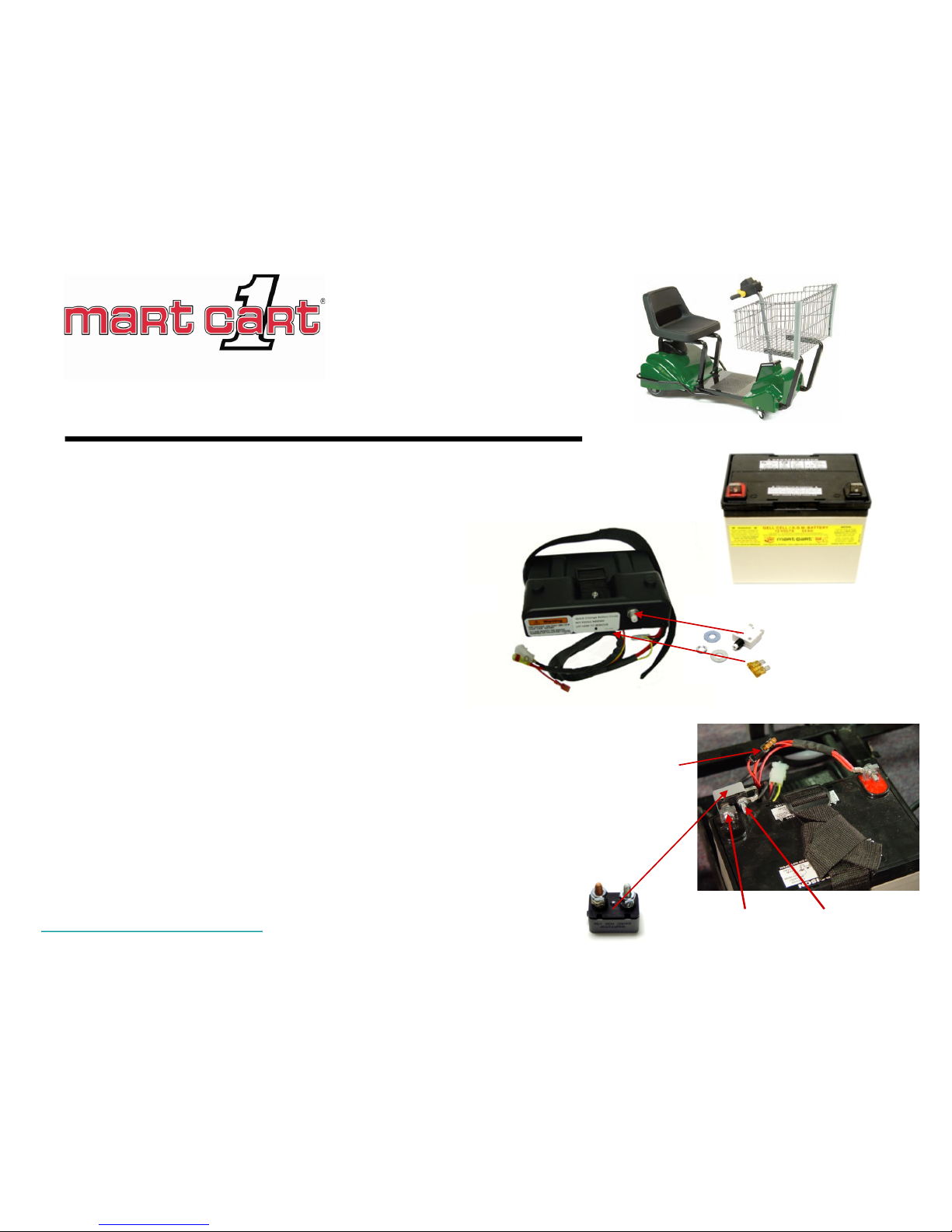
The battery is a 12 volt, AGM (Absorbent Glass Mat), 35 Amp
Hour, Sealed Lead Acid (SLA) battery.
Battery/Circui t Breaker
The “quick change” battery cover houses
the 15 amp circuit breaker, 5 amp fuse,
and main wire harness.
Copper Stainless
Prior to the quick change battery cover , a 15 amp circuit breaker was
attached directly to the negative pos t of the battery. The copper terminal of
the circuit breaker is attached to the battery term inal with a lock nut. The
black wire lead of the main wire harness is attached to the stainless steel
terminal of the circuit breaker.
260-1228
280-1214
280-1610
280-1712
280-1627 (Fuse)
280-1799
(Mini Fus e )
Page 5
Return to Major Parts Overview
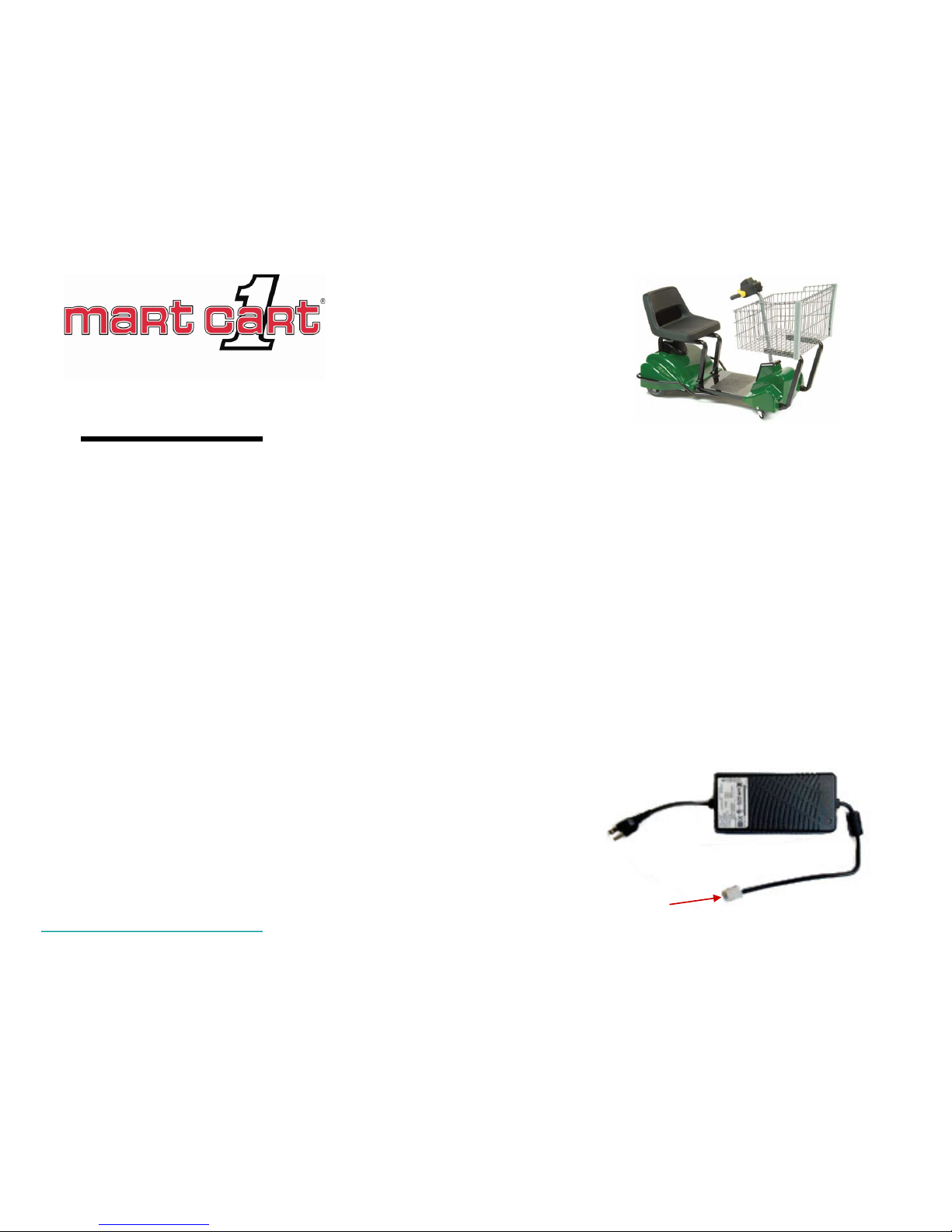
The charger is a 12 volt, 7amp charger with Intelli-Charge™ functionality.
Intelli-Charge monitors the charge capacity of the batt ery. The charger shuts down when t hen
battery is completely c harged. This feature allows the battery to be plugged i nto a wall soc k et
for any length of time without concern about over-charging.
The charger has 3 output wires and is plugged di rectly into the main wire harness with a 3-pin
connector. The positi ve and negati ve wires go to the battery, and an “inhibit” wire goes to the
PWM.
The inhibit wire carries v oltage t o the PWM on pin 7 when the charger is plugged in and
charging the battery. Voltage on pin 7 “inhibits” the PWM from outputting voltage to the motor
thus not allowing the cart to be operated when the charger i s plugged i n.
Charger
280-1749
3-pin connector
Note: The charger uses power cord 280-1797. The previous
version of the charger uses power cord 280-1647 (“D” Plug).
Page 6
280-1454
280-1646
Return to Major Parts Overview
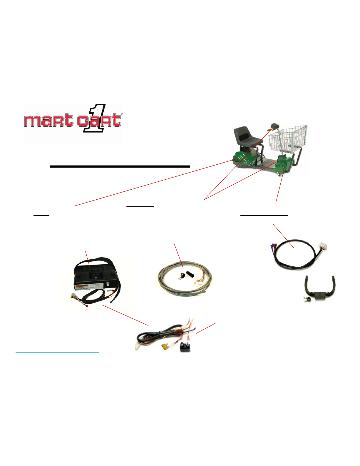
Wire Harness
Main – part of the quick-
change battery cover
assembly. Contains
15 amp circuit breaker
and 5 amp mini fuse.
Steering – includes 6-pin, 3-pin,
and 10-pin
connectors, clamps
and 18 inch loom
(not shown).
PWM-to-Motor - includes 4-pin
connector.
The earlier version of the main wire
harness without the quick-change
battery cover contains a 15amp
circuit breaker and 5amp fuse.
280-1712
280-1202
280-1626
(Wire Guide)
Page 7
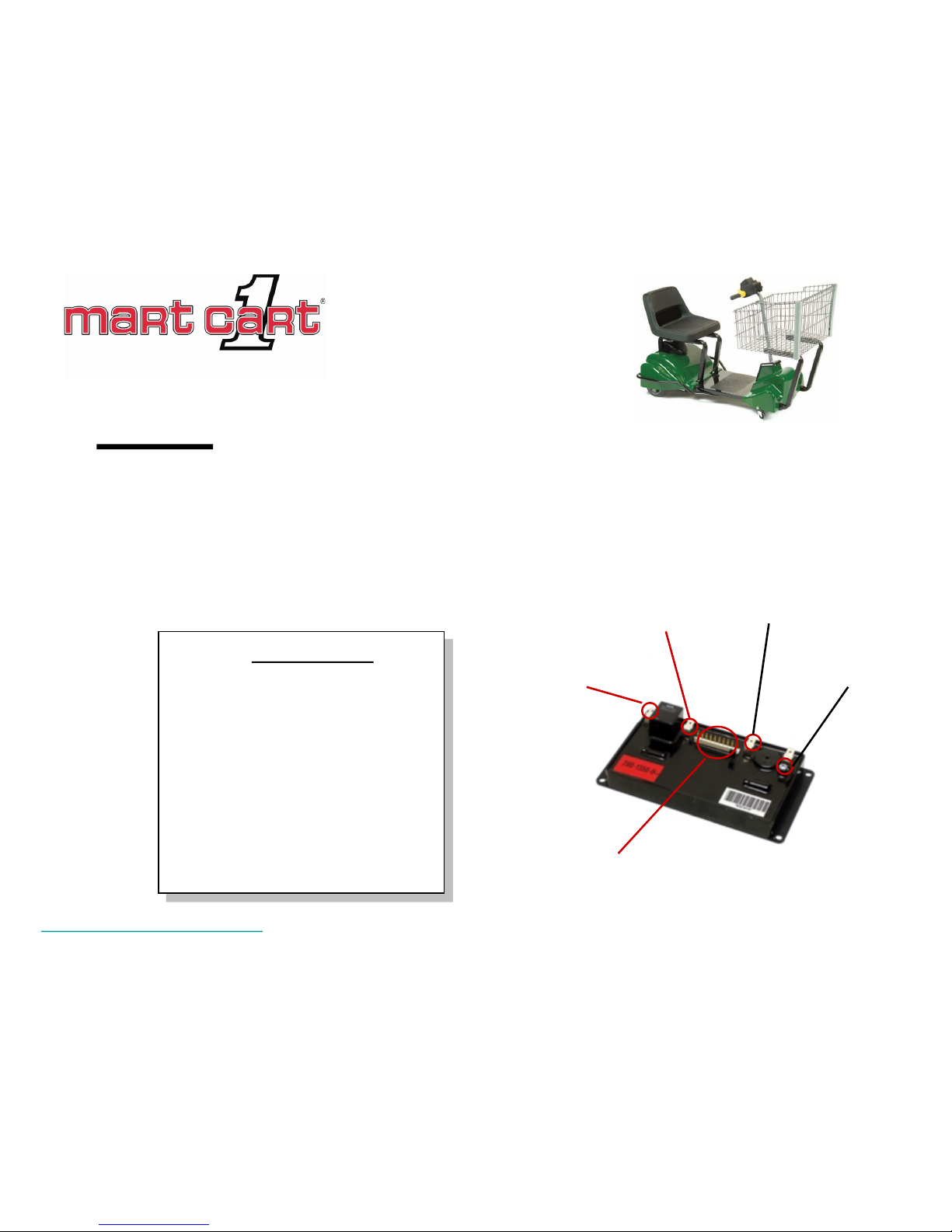
The PW M (Pulse Width Modulator) monitors mul tiple el ectroni c funct ions and i s the central
processor for the cart’s electronics. The PWM (in conjunction with the potent iom eter) control s the
speed and direction of the m otor hub.
A 10-pin terminal is designed to monitor the cart’s functions through the control box, charger, and
motor.
Return to Major Parts Overview
PWM
10-pin terminals
1 – Black – Pin 1 on pot (ground)
2 – Yellow – Pin 2 on pot (wiper)
3 – Blue – Pin 3 on pot (terminal)
4 – Green – LED
5 – Orange – LED
6 – White – Common (power)
7 – Yellow – Inhibit fro m charger
8 – Violet – Horn
9 – Brown – Brake
10 – Not used
10-pin Terminal
Positive
Battery Terminal
Negative
Battery Terminal
Negative
Motor Terminal
Positive
Motor Terminal
280-1569
Page 8

Return to Major Parts Overview
The control box houses the potentiom eter and rocker switch (Power Off/On, Horn, LED light).
The potentiometer is connected to the c ontrol throttl e and regulates the resis tance on pi ns 1,
2, and 3 of the PW M. This, in turn, controls the speed and direction of the motor.
The rocker switch has an im bedded LE D that i ndic ates the battery charge process when the
charger is plugged in and indic ates the battery charge lev el while the c art is in servi ce.
Control B ox
When charging
Amber - Charging
Green - Charged
When in service
Green - Good Charge
Amber - Moderate Charge
Red - Low (needs charging)
280-1228
280-1187
280-1405
(Rocker Switch)
Note: The contr ol box ha s optiona l configurations .
Please call the Service Departmen t for detailed
information.
Page 9

The hub motor is a direct current, brushed disc , 12 (or 24)
volt brake, geared motor.
The motor is powered through a posit ive (red) and a
negative (black ) wire lead protruding from the axle.
The brakes are powered by two black wire leads
protruding from the opposite axle.
The wire leads are pinned and inserted i nto a 4-pin
connector. The brak e leads are inserted i nto slot s 1 and 2.
The negative power lead i s inserted into s lot 3 and the
positive lead (red) is inserted into s lot 4.
Return to Major Parts Overview
Hub Motor
280-1600
Page 10
Potentiometer/PWM
Relationship
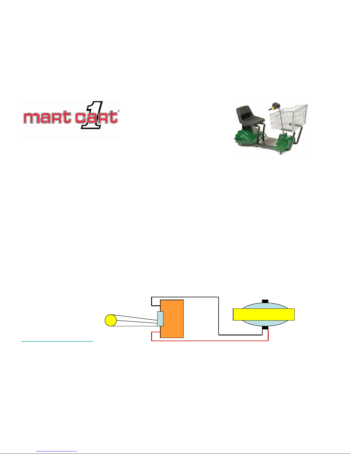
The potentiometer (pot) along with the P WM regulates the speed and direction of the m otor. The
PW M monitors the change in resistanc e on pins 1, 2, and 3 of the 10-pin connector which are
connected to the pot (pins 1, 2, and 3 respectively) through the steering wire harness. The pot is
located in the control box and is physically connected to the throttle control on the cart’s
handlebars. The resistance is v aried by the m ov em ent of the thumb-control throttl e in a forward
and backward direction.
In turn, the PWM emits variable voltage to the positive and negative m otor leads (c onnected to the
PW M), allowing the m otor to move at varied speeds forward and backward.
The pot is rated at 5K ohms +/- 10%. This is the resistance between pin 1 and pin 3 on the pot’s
terminals. When the pot assembly is set at the factory, the wiper (pin 2) is calculated and preset to
24% of the total resistance (approx 1.08K to 1.32K ohm s). The wiper position of the pot is where
the PW M looks for the “neutral” position. In the neutral positi on, the P WM cuts power to the motor
leads and brake leads (engaging the brak e).
Continued on next page
1
2
3
Pot PWM
Hub Motor
Page 11

Return to T able of Contents
Potentiometer/PWM
Relationship
Over the life of the cart, several things may happen to disrupt the normal resistance between the
pot and the PWM…subsequently sending false readings to the PWM. They are:
• The resistance material in the pot becom es dam aged (extremel y rare).
• The shaft sticks/freezes (human error during assem bly).
• The spring or fork of the pot assembly becom e dam aged.
• The connectors of the steering wire harness loose contact.
• The wires of the steering wire harnes s break .
W hen any of these situations occur, the PWM (movement of the cart) may act erratically. Often, the
PW M is diagnosed as having a problem when, in fact, a problem exists with the pot, connec tors, or
wire harness.
The PWM is “calibrated” (see next page “Cali brate PWM”) at the factory to the neutral range of the
pot. If the pot assembly or wires become dam aged, the resistance (and neutral range) of the pot
can change. Re-calibrating the PWM may resolve the immediate problem but the fix may not be
permanent. The best practice is to validate the condition of the pot, connect ors, and wire harness
before attempting to re-calibrate the PWM.
Page 12

Continue on next page
Calibrate P WM
1. Stand next to the cart. Do not sit on the seat during the calibration st eps.
2. Turn the rocker switch to the “ON” position (and the k ey switch if so equipped).
3. Be sure that the throttle is in neutral posi tion (hands off).
4.
Hold down the horn button for a minim um of 10 seconds. Do not let off of the horn.
5. W hil e continuing to hold down the horn, push down and then rel ease i n the center of the seat
(activating seat switch) 3 times.
6. Wait a second or two and then release the horn.
If you hear 2 short chirps, the PW M calibrated successfully.
Retest the cart.
If you hear 3 short chirps, the PWM did not recognize a brake
circuit (see the next page “Chec k Brak e Lead”).
If you hear a long chirp in any combination, the P WM did not
calibrate successful ly. Calibrate again or replace the PWM.
On occasion, the cart m ay function erratical ly. As the last step in troubles hooting a problem, the
PW M can be “calibrated” to the neutral posi tion of t he potentiom eter. Be certain that the battery i s
charged above 10.5 volts and the horn and the seat switch are connected and working properly
before attempting to cal ibrate the P WM. Without them working properly, the P WM will not calibrate.
Turn on sound and cli ck video
Page 13

Return to T able of Contents
Calibrate PWM –
Check Brake Leads
W hen attempting to calibrate the PWM one might hear 3 short chirps. This indicates that the PWM
did not recognized a brak e circuit. The PWM will still function but the brakes will not rel ease caus ing
undesired performance from the motor. To resolve the brake issues, check the brake circuit from the
PW M to the motor by disconnecting the brake leads from the wire harness at the PWM and placing
an ohm meter on each lead. The meter should read approximately 20 ohm s .
If you do not get a good reading, run the same test on brake leads from the motor to the 4-pin
connector.
If you do not get a good reading there, either the male
pins in the connector are bad or the brake circ uit ins ide
the hub motor is bad…repair the pins or replac e the
motor.
If you get a good reading, then the PWM-to-Motor wire
harness is bad or the pins in the 4-pin connector are not
making good contact…repair the pins or replace the
harness.
Brake Leads
Page 14

Parts List
Return to T able of Contents
Item Part# Description
1 280-1818 Main Frame (contains Bumper/hardware)
1a 280-1840 Bumper Only (with hardware)
2 280-1268 Rear Wheels – Poly-U, 8”
3 000-1224 Bushing – 5/8” (1 on each wheel)
4 280-1335 Grommet – 5/8” (1 on each wheel)
5 000-1075 Retaining Ring “E” Type (1 on each wheel)
6 280-1214 Battery – 35AH
7 280-1797 Charger Cord – 6’ Coiled (See Notes)
8 260-1228 Circuit Breaker – 15amp (See Notes)
9 280-1743 Charger – 7AMP, 3-Prong Pigtail
10 280-1799 Fuse, Mini – 5AMP (See Notes)
11 280-1712 Battery Cover Assem bl y – (See Notes)
12 280-1280 Rear Cover (Select Color Options)
13 280-1637 Charger Cord Cover
14 280-1711 Spring Latch Assembly
15 280-1262 Seat Mount Tube – LH
16 280-1261 Seat Mount Tube – RH
17 280-1797 Seat, PVC-Free (includes Seat Switch)
17A 200-1558 Seat, Padded (Optional – includes Seat Switch)
18 280-1553 Seat Switch (for PVC-Free Seat 280-1797)
18A 280-1484 Seat Switch (for Padded Seat 200-1558)
19 280-1264 Basket Tube (2 each)
20 200-1802 Basket, Lil Max
20A 280-1614 Basket Bumpers – 15” (2 each)
21 200-1236 Basket Mounting Clips (4 each)
22 280-1626 Wire Guide (See Notes)
23 280-1202 Wire Harness – Steering
24 280-1646 Wire Harness – Hub Motor to PWM (See Notes)
25 280-1569 PWM (Pulse W idth Modulator)
26 280-1454 Wire Harness – Main (part of Battery Cover Assembly)
27 280-1346 Tire for Hub Motor
28 280-1279 Front Cover (Select Color Option)
29 280-1441 Bridge Cover
30 280-1600 Hub Motor
31 200-1052 Caster – 2” (2 each)
32 280-1273 Fork Assembly
33 280-1281 Floor Cover
Steering Column/Controls (See Detail on next page )
Notes:
7 Use Charger Cord 280-1647 (“D” plug) if cart has 280-1630 charger (older version).
8 Use Circuit Breaker 280-1610 if cart does not have the Battery Cover 280-1712.
10 Use Fuse 280-1627 if cart does not have a Battery Cover 280-1712.
11 Battery Cover Assembly 280-1712 contains Main Wire Harness, Fuse, and Circuit Breaker.
22 Wire Guide Assembly (280-1656) contains Wire Guide (280-1626), Wire Harness (280-1646), and Hardware.
24 Wire Guide Assembly (280-1656) contains Wire Guide (280-1626), Wire Harness (280-1646), and Hardware.
26 Order this part only if cart does not have Battery Cover 280-1712.
Optional Parts
Part# Description
290-1123 Jr Basket
280-1373 Jumbo Basket (w/castors and lower shelf)
200-8153 Folding Produce Tray
280-1562 Chek-Riter
280-1653 Safety Flag
200-1393 Cord Reel – 6’
280-1178 Hour Meter
200-1728 Crutch Holder Assembly
280-1440 Seat Latch Hook Assembly
Decals/Signs ( English – call f or other)
Part# Description
200-1382 Sign – Operating Instructions
200-1387 Sign – Personal Injury
200-1231 Sign – No Children
200-1299 Decal – Personal Injury
200-1095 Decal – Load Limits
280-1307 Decal – Pull Latch
000-1183 Decal – High Voltage
280-2103 Decal – Do Not Stand
280-1545 Decal – Charging Instruct ions
280-1532 Decal – Daily Maintenance
Page 15

Return to T able of Contents
Parts List –
Steering Column
Steering Column and Cont rol Box Pa rts List
Item Parts# Description
1 280-1178 Control Box Bottom Cover
2 280-1177 Control Box Top Cover
3 280-1184 Control Box Divider
4 280-1187 Potentiometer Assembly
5 200-1640 Key Switch (Optional)
6 280-1405 Rocker Swi tch
7 280-1863 Overlay – Control Box Top
8 280-1185 Overlay – Control Box Front
9 280-1862 Intelli-Charge Indicator Decal
10 280-1602 Grip
11 280-1179 Throttle Grip – Thumb Control
12 280-1199 Steering Column (w/Rod and Grips)
Control Box Kits
280-1228 Control Box – Keyless (1-4, 6-8)
280-1229 Control Box – Keyed (1-8)
280-1230 Control Box Top – Keyless (2, 4, 6-8)
280-1231 Control Box Top – Keyed (2, 4-8)
280-1232 Control Box Top – w/Decals (2, 7, 8)
Page 16
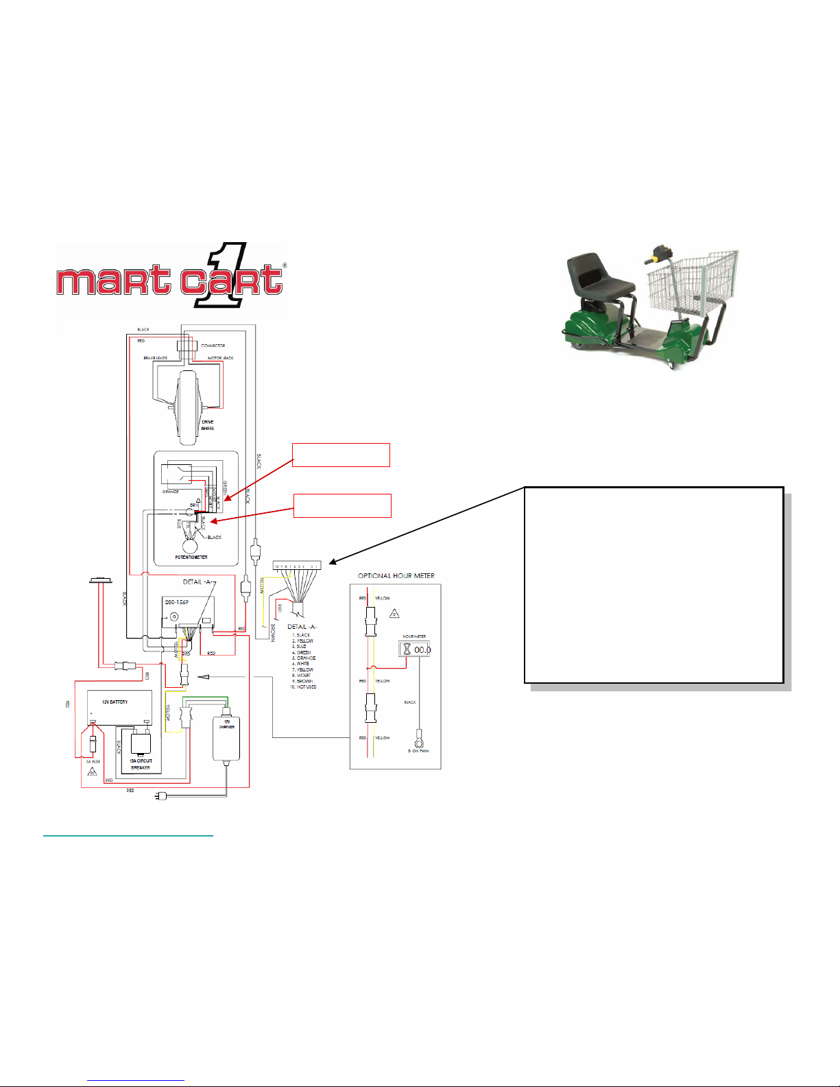
Wiring Diagram
1 – Black – Pin 1 on pot (Neg)
2 – Yellow – Pin 2 on pot (wiper)
3 – Blue – Pin 3 on pot (terminal)
4 – Green – LED
5 – Orange – LED
6 – White – Power (Pos)
7 – Yellow – Inhibit fro m charger
8 – Violet – Horn
9 – Brown – Brake
10 – Not used
Return to T able of Contents
6-pin connector
3-pin connector
Page 17
Return to T able of Contents
Tools
The suggested tool kit should contain:
Screwdrivers: #2 Phill ips
T15 Star
#2 Flat Head
Wrenches: 3/4” Open End
1/2” Open End
1/2” Box End
10mm Open End
Torque
Punch or Nail: 1/8”
Sockets: 5/16”
1/4”
7/16”
1/2” Deep Well
1/2”
10mm
Pliers: Needle Nose
Regular
Wire Snips
Electronics: Multi-meter - Ohms, AC and DC voltage
Load Tester - Should be able to load test battery
without having to charger the battery first
Jumper cable- Alligator clips on both ends
Page 18

Return to T able of Contents
Safety Check
• General Condition – Check for broken frame, tubes, bumpers (frame and basket), basket, handlebars, covers, seats, and armrests.
Any part or piece that may snag a person or store display should be repaired. All mounting screws (e.g. front cover screws) should be
checked and replaced as necessary.
• Electrical components – Check all wiring to ensure no evidence of fraying, crimps or cuts. Ensure that the harness is laying inside
the rear pan and not in a bind or contact with metal parts or components that could rub through the insulation (for example – between the
seat tube and frame on an XTi model cart). Ensure proper circuit breakers are installed and functional.
• Charger cord – In addition to the other electrical components, check for fraying of charger cord and cord plug for damage. Replace
with OEM cord. It is not recommended to replace plug.
• Casters – Check for proper distance from the floor (about ½ inch). Check for bracket welds and position (perpendicular to the floor).
• Seat Latch – Ensure that the latch engages properly and that it secures the seat from tilting forward.
• Horn – Check for proper functionality and audible level. The horn should activate when pressed and when the cart is moving in reverse.
• Grips – Check the grips on the handlebars to ensure that they firmly grasp. The grips should not be easily twisted or removed.
• Charger – Check the “inhibit” functionality of the charger. Ensure that the cart does not move under pow er when plugged into a power
outlet and charging the battery.
• Seat Switch – Ensure that the cart only moves under power ONLY when someone is sitting in the seat. Occasionally, the seat switch
may be bypassed (jumpered) during cart maintenance to facilitate problem diagnosis. Never leave the seat switch bypassed for
normal oper ation.
• Wheels and Axle – Ensure that wheels are properly aligned, bearings are functional, and axle is not bent or bowed. Check for flat
spots and wear.
This checklist is designed for service technicians to use as a guideline when servicing electrical Mart
Cart shopping carts. The list covers common system safety features that should be checked for proper
installation and functionality. While they may not be presented on this list, all parts and components of
the cart should be checked for proper functionality and either fixed or reported to authorized facility
personnel. All parts must be OEM to ensure proper safety and warranty compliance.
Page 19

Return to T able of Contents
Warranty
The warranty period is calculated from the
month and year of manufacture. The month
and year of manufacture is determined by the
punch-out positions on the serial number label.
In a standard, 2-year warranty period, a cart
would be out of warranty in 2 years on the
month following the month punc he d o ut.
Example: Cart built October, 2008 would be in
warranty through October , 2010.
Warranty periods can differ from customer to customer.
Please call our Service department for verification of
warranty periods.
Page 20
Return to T able of Contents
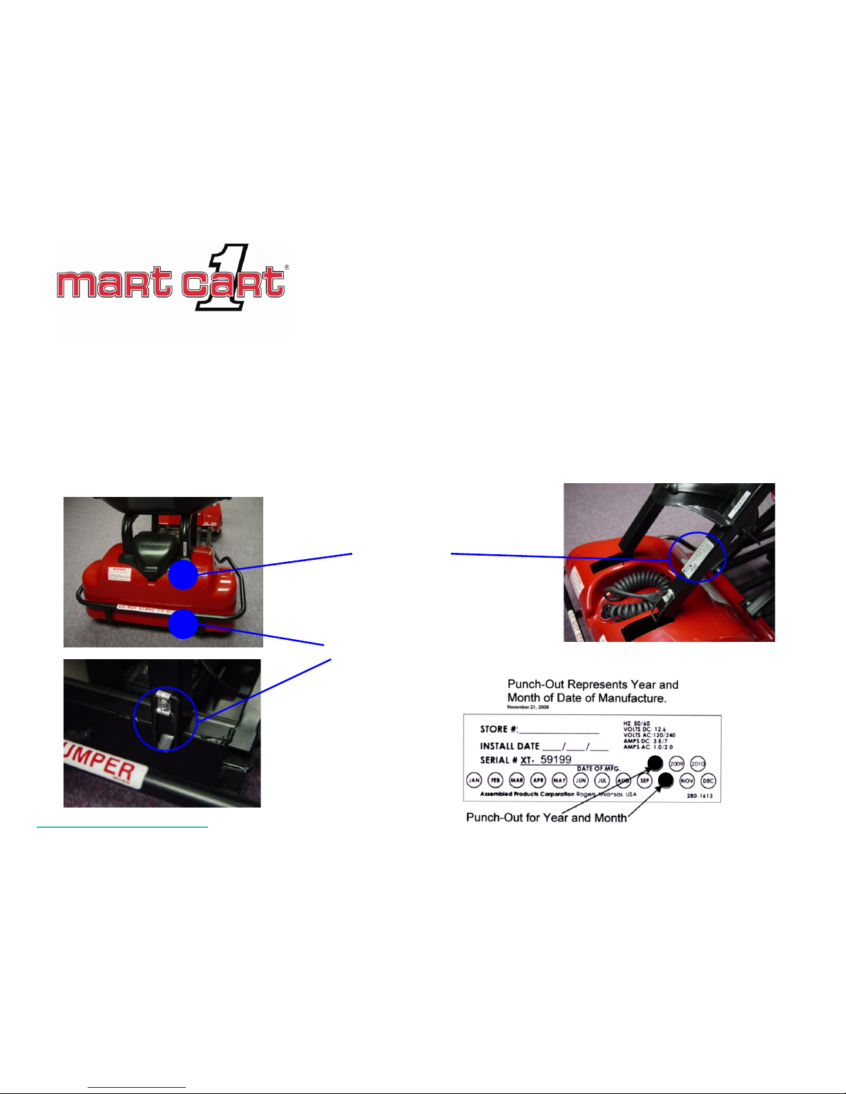
Serial Number Label
SN Label
Location
Latch
The serial number label is located underneath the rear cover. The manufacture date is represented by
the year and month “punch-out” as shown below (review the previous page for warranty period
information.
Lift the spring loaded seat latch (hidden
below the cove r) and pus h forwa rd on the
seat to reveal the label.
Page 21

Mart Cart
End
Technical Ov erview
 Loading...