

Page 1
-1-
`
TECHNICAL MANUAL
WM: REMOTE WIRED HIGH WALL SPLIT SYSTEMS
WM L, WM E: INFRARED HIGH WALL SPLIT SYSTEMS
INDOOR UNIT: 556 series WM, WM L, or WM E
MATCHED WITH: 550 series MCU or MCU+ condensing units (MCUP=MCU+ in Germany)
551 series MHPUE or MHPUL heat pump units
542 series DCUE ducted condensing units
543 series DHPUE ducted heat pump unit
GENERAL Part numbers 2
Dimensions and weights 3
Unit combinations, features/accessories 4
Essential Range systems 4
PRODUCT Optional electric heating 5
SELECTION Airflows, air throws 5
Sound power and pressure levels 6
Performance data 7
Electrical data 8
Fuses 9
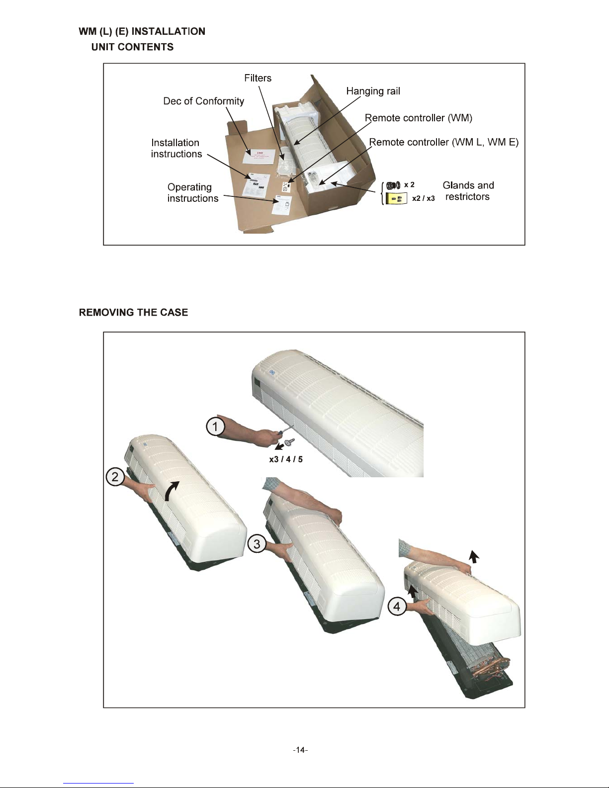
INSTALLATION WM (L) (E) unpacking 14
Removing the case 14
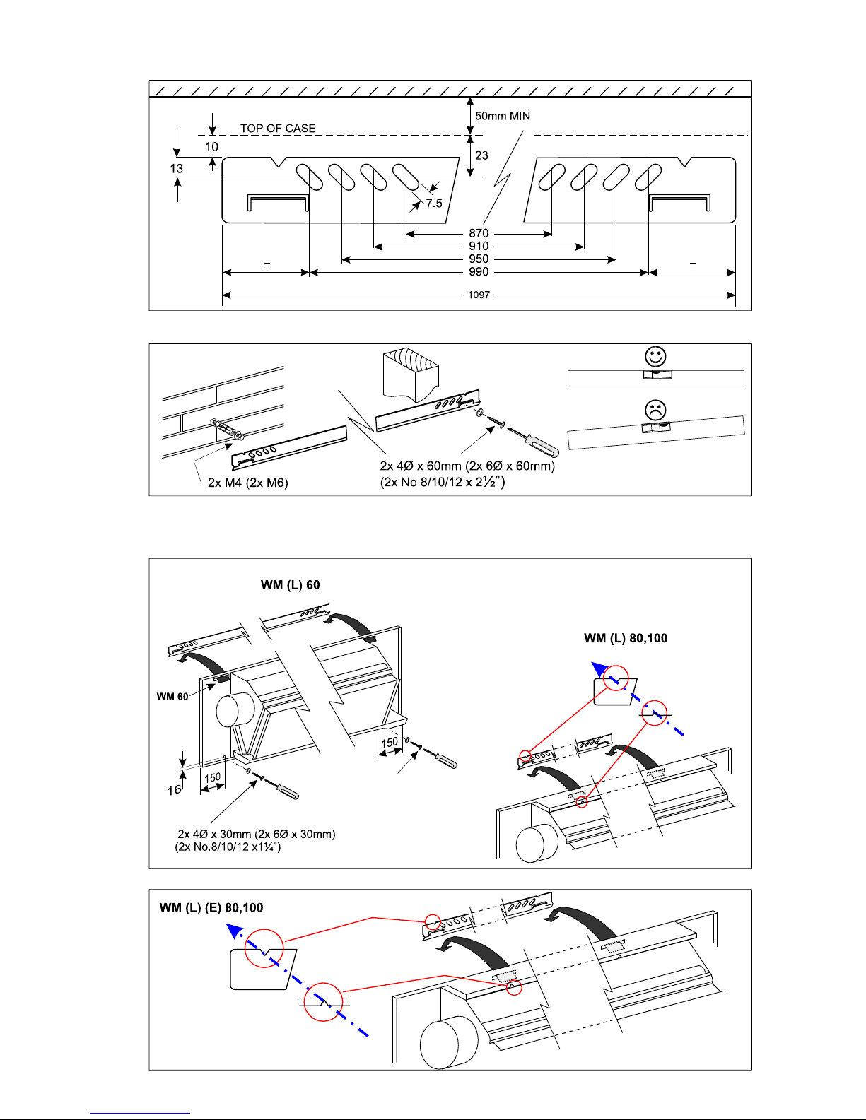
Hanging the unit 15
Pipework and restrictors 16
Gravity drain; cable routing 17
Fitting the case 17
Fitting filters
MCU, MCU+, MHPUL, MHPUE installation 18
DCUE, DHPUE installation 19
Pipe sizing 20
Interconnecting wiring 22
WM L pcb jumper configuration 23
Remote controller WM (RCC 30: including operation) 24
WM L 25
WM E 25
Evacuating and charging 26
Adding refrigerant and oil 27
Check list: filter maintenance 28
WIRING WM, WM L, WM E 29
DIAGRAMS MCU, MCU+, MHPUL, MHPUE 32
DCUE, DHPUE 35
Interconnecting diagrams 38
WM (L) (E) KITS Remote return air sensor (for WM RCC30 controller) 41
Programmable timer (for WM) 41
Electric heaters 42
5m high condensate pump 44
EMC termination kit 46
BMS alarm interface kit 47
OPERATING Infrared WM L 48
INSTRUCTIONS Infrared WM E 50
COMPONENT Exploded view of chassis with component identification 54
IDENTIFICATION Exploded view of case 55
Outdoor units 56
Ducted units 57
FAULT FINDING All models 58
Marstair Ltd,
Armytage Road, Brighouse,
West Yorkshire, HD6 1QF, UK. 55699105-03
Tel: +44 (0) 1484 405600
Fax: +44 (0) 1484 405620
Email: [email protected]
Page 2
-2-
MARSTAIR LIMITED - WM HIGH WALL SPLIT SYSTEMS
The WM range of split systems consists of WM high wall units using remote wired controllers and WM L and WM E high
wall units using infrared controllers matched with 550 series condensing units, 551 series heat pump outdoor units, 542
series electronic ducted condensing units or 543 series ducted heat pumps.
By choosing appropriate combinations, the installer can provide:
AIR CONDITIONERS with a cooling range of 3.7-8.2 kW,
or HEAT PUMPS with a cooling range of 3.7-8.2 kW, and a heating range of 4.2 -9.1 kW (7°C outdoors)
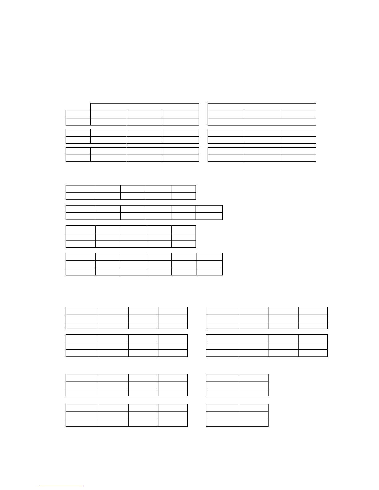
PART NUMBERS
WM (L)(E) INDOOR UNITS
Cool only Cool and heat
WM WM 60 WM 80 WM 100 WM 60 WM 80 WM 100
55600001 55600002 55600003 Electric heaters available as an option
WM L WM L 60 WM L 80 WM L100 WM L 60 WM L 80 WM L100
55600004 55600005 55600006 55600010 55600011 55600012
WM E WM E 60 WM E 80 WME 100 WM E 60 WM E 80 WME 100
55600007 55600008 55600009 55600013 55600014 55600015
550 Series CONDENSING UNITS (MCU/MCU+)
MCU 1Ph MCU 50 MCU 60 MCU 80 MCU90
R22
55022070 55022071 55022072 55022073
MCU 3Ph MCU 50 MCU 60 MCU 80 MCU90 MCU 100
R22
55022076 55022077 55022078 55022079 55022080
MCU+ 1Ph MCU+50 MCU+60 MCU+80 MCU+90
R407C
55022006 55022007 55022008 55022009
R22
55022028 55022029 55022030 55022031
MCU+ 3Ph MCU+50 MCU+60 MCU+80 MCU+90 MCU+100
R407C
55022013 55022014 55022015 55022016 55022017
R22
55022034 55022035 55022036 55022037 55022038
551 Series HEAT PUMP UNITS (MHPUL) 551 Series HEAT PUMP UNITS (MHPUE)
MHPUL 1Ph MHPUL 50 MHPUL 80 MHPUL 90 MHPUE 1Ph MHPUE 50 MHPUE 80 MHPUE 90
R407C
55122044 55122046 55122047
R407C
55122005 55122007 55122008
R22
55122062 55122064 55122065
R22
55122023 55122025 55122026
MHPUL 3Ph MHPUL 50 MHPUL 80 MHPUL 90 MHPUE 3Ph MHPUE 50 MHPUE 80 MHPUE 90
R407C
55122050 55122052 55122053
R407C
55122011 55122013 55122014
R22
55122068 55122070 55122071
R22
55122029 55122031 55122032
542 Series DUCTED CONDENSING UNITS (DCUE) 543 Series DUCTED HEAT PUMP UNIT(DHPUE)
DCUE 1Ph DCUE 50 DCUE 60 DCUE 80 DHPUE 1Ph DHPUE 50
R407C
54200031 54200032 54200033
R407C
54300018
R22
54200006 54200007 54200008
R22
54300004
DCUE 3Ph DCUE 50 DCUE 60 DCUE 80 DHPUE 3Ph DHPUE 50
R407C
54200037 54200038 54200039
R407C
54300021
R22
54200017 54200018 54200019
R22
54300007
Page 3
-3-
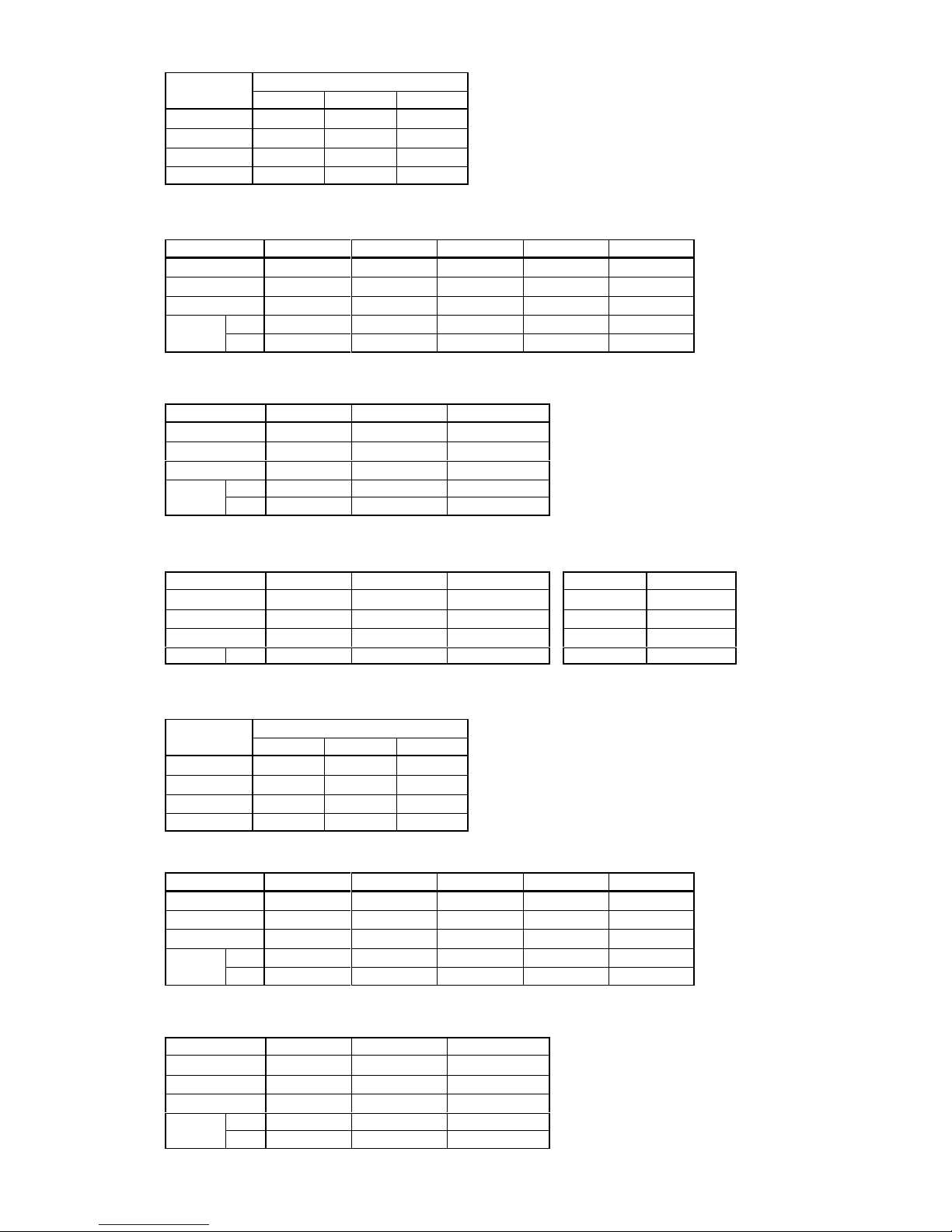
UNPACKED DIMENSIONS AND WEIGHTS
Model
WM (L) (E)
60 80 100
HEIGHT mm 350 350 350
WIDTH mm 1200 1500 1800
DEPTH mm 223 223 223
WEIGHT kg 19 23 27
CONDENSING UNITS
Model
MCU(+)50 MCU (+) 60 MCU (+) 80 MCU (+) 90 MCU (+) 100
HEIGHT mm
720 720 720 820 820
WIDTH mm
1000 1000 1000 1000 1000
DEPTH* mm
300 300 300 350 350
WEIGHT
kg
1 Ph
64 65 66 76 -
3 Ph
62 63 64 73 81
* excluding 10mm grille
HEAT PUMP OUTDOOR UNITS
Model MHPUL(E) 50 MHPUL(E) 80 MHPUL(E) 90
HEIGHT mm
720 820 820
WIDTH mm
1000 1000 1000
DEPTH* mm
300 350 350
WEIGHTkg1 Ph
64 75 77
3 Ph
62 72 75
* excluding 10mm grille
DUCTED CONDENSING UNITS DUCTED HEAT PUMP
Model
DCUE 50 DCUE 60 DCUE 80 Model DHPUE 50
HEIGHT mm
625 625 625
HEIGHT mm
625
WIDTH mm
1245 1245 1245
WIDTH mm
1245
DEPTH mm
565 565 565
DEPTH mm
565
WEIGHT 1 Ph
81 81 84
WEIGHT kg
95
PACKED DIMENSIONS AND WEIGHTS
Model
WM (L) (E)
60 80 100
HEIGHT mm 345 345 345
WIDTH mm 1350 1650 1950
DEPTH mm 480 480 480
WEIGHT kg 23 28 33
CONDENSING UNITS
Model
MCU(+)50 MCU (+) 60 MCU (+) 80 MCU (+) 90 MCU (+) 100
HEIGHT mm
720 720 725 825 825
WIDTH mm
1080 1080 1080 1090 1090
DEPTH mm
340 340 340 390 390
WEIGHT
kg
1 Ph
66 67 67 78 -
3 Ph
64 65 65 75 83
HEAT PUMP OUTDOOR UNITS
Model MHPUL(E) 50 MHPUL(E) 80 MHPUL(E) 90
HEIGHT mm
720 825 1085
WIDTH mm
1080 1090 1090
DEPTH mm
340 390 465
WEIGHTkg1 Ph
66 77 -
3 Ph
64 74 105
Page 4
-4-
DUCTED CONDENSING UNITS DUCTED HEAT PUMP
Model
DCUE 50 DCUE 60 DCUE 80 Model DHPUE 50
HEIGHT mm
660 660 660
HEIGHT mm
700
WIDTH mm
1270 1270 1270
WIDTH mm
1270
DEPTH mm
610 610 610
DEPTH mm
610
WEIGHT 1 Ph
86 86 90
WEIGHT kg
101
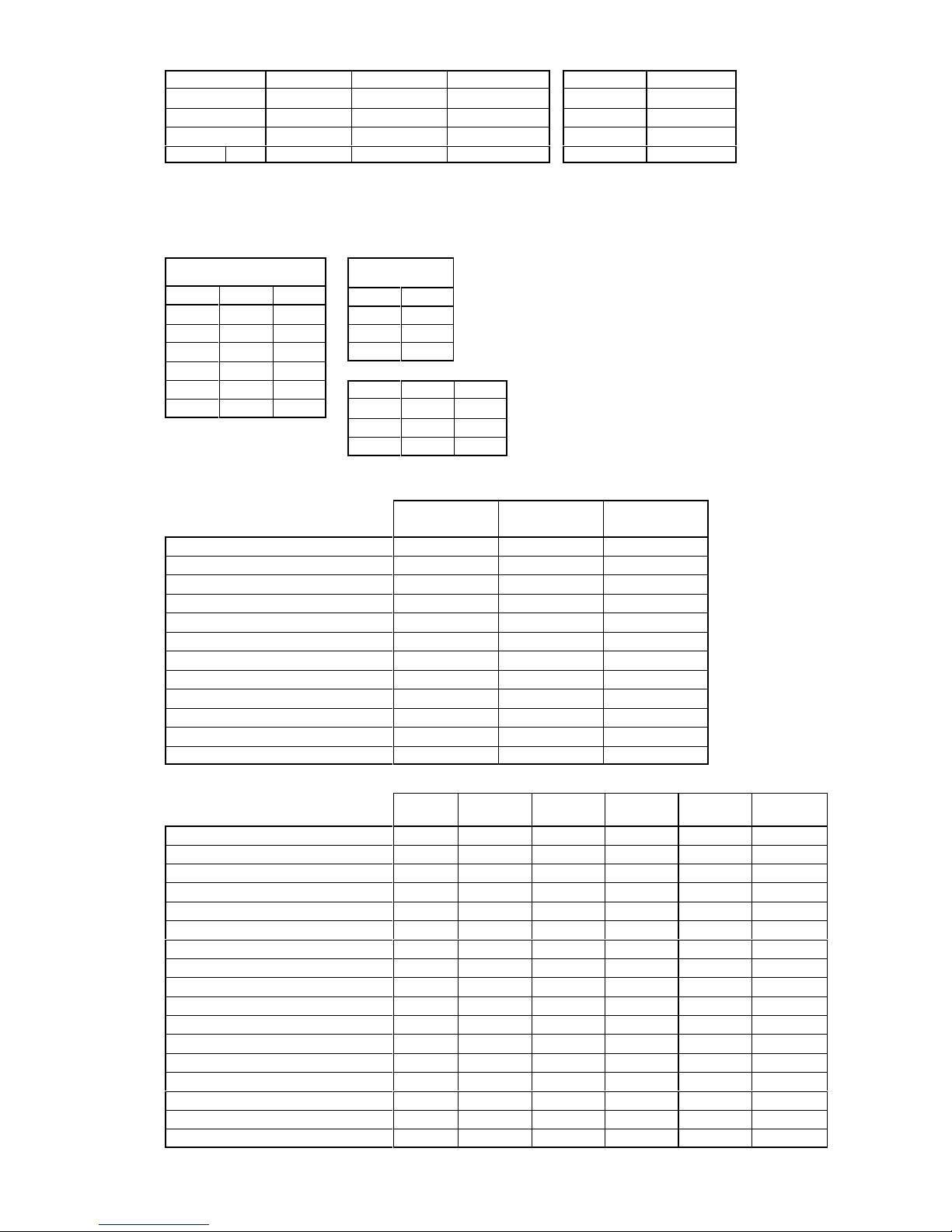
UNIT COMBINATIONS
Combinations of indoor unit and (ducted) condensing/heat pump unit can be chosen to give either air conditioning or heat
pump systems.
Air Conditioners Heat Pumps
WM MCU(+) DCUE WM L MHPUL
60 50 50 60 50
60 60 60 80 80
80 80 80 100 90
80 90 -
100 90 -
WM E MHPUE DHPUE
100 100 - 60 50 50
80 80 -
100 90 -
FEATURES/ACCESSORIES
INDOOR UNITS
WM WM L WM E
Top air discharge STD STD STD
Adjustable air deflection STD STD STD
Long life washable filter STD STD STD
3 fan speeds STD STD STD
De-ice thermostat STD STD STD
Electric heating
***
Remote hard wired control STD ---
*
Remote temperature sensor
*
--- ---
Programmable timer
*
--- ---
Remote infrared control ---
**
Gravity drain STD STD STD
5m high condensate pump
***
OUTDOOR UNITS
MCU MCU+ MHPUL MHPUE DCUE DHPUE
Fan speed head pressure control
*
STD STD STD STD STD
HP cutout auto (with manual backup) --- --- --- STD STD STD
HP cutout auto --- STD --- --- --- --HP cutout manual
***
--- --- ---
LP cutout auto
*
STD STD STD STD STD
3 minute start time delay
*
STD STD STD STD STD
Low ambient start
*
STD STD STD STD STD
Random start
*
STD STD STD STD STD
Volt free relay (for remote alarm)
****
--- --Contactor STD STD STD STD STD STD
Overload 1Ph (standard on 3Ph)
******
Isolator (for remote mounting)
******
Isolator mounted on unit
--- --- --- ---
**
Wall mounting brackets
******
Heat pump condensate drain tray --- ---
**
---
*
Ducting kits --- --- --- ---
**
Compressor jacket
****
--- ---
STD = Standard
* = site accessory ---- = not available
Page 5
-5-
OPTIONAL ELECTRIC HEATING (kW)
WM (L) (E)
230V 50Hz 240V 50Hz
60
1.2 1.3
80 1.7 1.8
100 2.1 2.3
AIRFLOWS
WM (L) (E)
LOW SPEED MEDIUM SPEED HIGH SPEED
m
3
/s m3/s m3/s
60 0.17 0.19 0.28
80 0.24 0.31 0.37
100 0.25 0.34 0.49
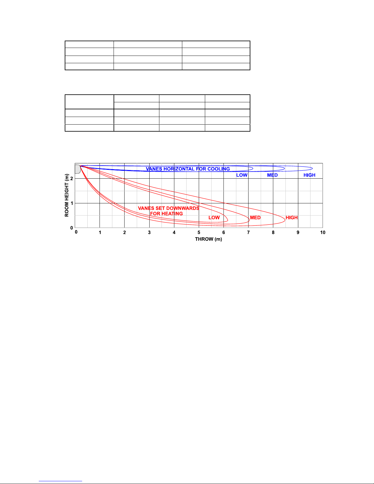
AIR THROWS
--o--o--O--O--O--o--o--
Page 6
-6-
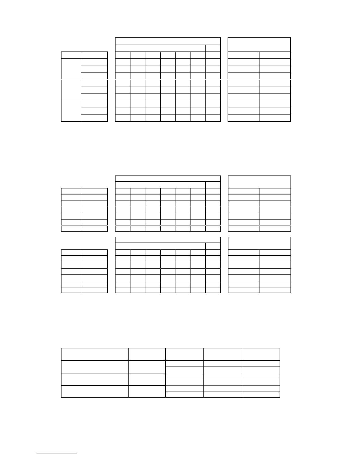
SOUND POWER and SOUND PRESSURE LEVELS
556 SERIES WM (L) (E)
SOUND POWER LEVELS
SOUND PRESSURE LEVELSFrequency Hz
MODEL SPEED 125 250 500 1K 2K 4K dBA dBA NC
60
MIN 36.8 37 39.1 38.8 34.4 31.7 43 25 19
MED 41.0 43.4 45.8 45.1 39.6 35.4 49 31 25
MAX 46.7 48.6 50.6 50.4 46.6 39.0 54 37 31
80
MIN 39.1 44.3 47.2 46.8 41.6 40.8 51 33 27
MED 43.8 49.1 51.3 51.3 46.7 39.5 55 37 32
MAX 45.5 50.5 53.7 52.9 48.7 40.8 57 39 34
100
MIN 34.1 38.0 44.0 42.3 41.0 38.0 48 30 24
MED 42.7 45.8 48.9 49.1 44.2 38.1 53 35 30
MAX 46.4 51.6 54.2 54.2 49.9 42.9 57 40 35
Sound Power Levels obtained in conformance with BS 4196: Part 5: 1981. Values are shown in dB with a standard
reference of 1 pW.
Sound Pressure Levels are dB relative to 2 x 10
-5
N/m2 and are calculated from results measured in anechoic conditions.
Values relate to a position 3m away from the centre line of the unit, 1m down.
550/551 SERIES MCU, MCU+ MHPUL MHPUE
MAXIMUM SPEED
SOUND POWER LEVELS
SOUND PRESSURE LEVELS
Frequency Hz
MCU(+) MHPUL(E) 125 250 500 1K 2K 4K dBA dBA NC
50 50 73.6 68.2 67.1 65.5 61.1 53.4 70 49 44
60 - 72.9 67.7 67.8 66.4 61.9 54.1 70 50 45
80 - 70.9 68.6 68.1 65.3 59.5 53.8 70 49 43
- 80 75.4 72.9 69.1 68.8 62.6 56.6 72 52 47
90 90 81.8 71.8 69.2 68.6 63.1 57.4 73 52 47
100 - 79.4 73.7 71.5 68.5 63.8 58.1 73 53 47
MINIMUM SPEED
SOUND POWER LEVELS
SOUND PRESSURE LEVELS
Frequency Hz
MCU(+) MHPUL(E) 125 250 500 1K 2K 4K dBA dBA NC
50 50 67.4 64.1 66.0 63.6 58.7 51.8 68 47 42
60 - 67.4 64.3 67.1 66.8 60.7 51.7 70 49 45
80 - 69.4 66.5 66.9 62.1 56.1 51.6 68 47 41
- 80 67.5 63.4 64.4 64.2 57.4 51.0 67 47 43
90 90 79.0 65.4 64.9 61.5 58.5 53.7 68 47 40
100 - 75.3 69.4 70.9 63.7 59.7 53.6 70 50 46
Sound Power Levels obtained in conformance with ISO 3741: 1988. Values are dB with a standard reference of 1 pW.
Sound Pressure Levels are dB relative to 2 x 10
-5
N/m2 and are calculated from results measured in anechoic conditions.
Values relate to a position 3m away from the centre of the unit (in cooling mode); (add 3dBA or 3NC for units at an
intersection of a wall, add 1dBA or 1NC for high level wall mounted units).
SOUND PRESSURE LEVELS - DUCTED CONDENSING UNITS
Measurement Point Unit Fan Speed dBA NC
3m from unit in void
DCUE 50, 60, 80
DHPUE 50
Max 54 48
Min 44 31
Adjacent office area
DCUE 50, 60, 80
DHPUE 50
Max 42 28
Min 32 17
3m from discharge grille
DCUE 50, 60, 80
DHPUE 50
Max 52 44
Min 40 28
All readings taken from a typical application of a unit suspended in a ceiling void complete with 5m of insulated
ducting, conditioning an office directly below. Sound Pressure Levels are dB relative to 2x10
-5
N/m2.
Page 7
-7-
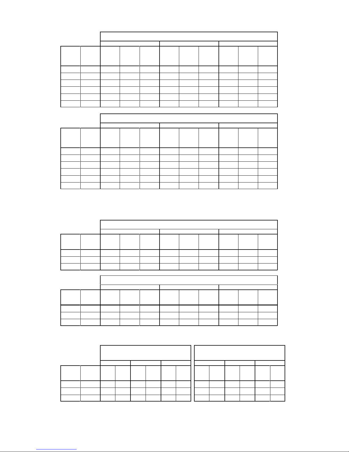
AIR CONDITIONER PERFORMANCE DATA (kW)
UK Conditions: Room 21/C / 15/C Ambient 27/C /19/C
Low Medium High
WM
WM L
WM E
MCU
MCU+
MCUP
DCUE
TOT SHR SENS TOT SHR SENS TOT SHR SENS
60 50 4.60.673.1 4.70.683.2 5.10.733.7
60 60 4.90.653.2 5.00.683.4 5.50.713.9
80 80 6.20.684.2 6.50.714.6 6.70.734.9
80 90 6.70.674.5 7.20.684.9 7.50.715.3
10090 7.10.664.7 7.70.695.3 8.30.756.2
100 100 7.4 0.66 4.9 8.2 0.68 5.6 8.9 0.73 6.5
NEMA Conditions: Room 27
/C / 19/C Ambient 35/C / 24/C (EUROVENT rating)
Low Medium High
WM
WM L
WM E
MCU
MCU+
MCUP
DCUE
TOT SHR SENS TOT SHR SENS TOT SHR SENS
60 50 4.90.653.2 5.10.673.4 5.40.744.0
60 60 5.30.643.4 5.40.673.6 5.90.714.2
80 80 6.60.674.4 6.90.714.9 7.00.765.3
80 90 7.30.644.7 7.80.685.3 8.00.715.7
10090 7.70.655.0 8.30.695.7 8.70.776.7
100 100 8.3 0.64 5.3 9.0 0.67 6.0 9.7 0.73 7.1
HEAT PUMP PERFORMANCE DATA (kW)
a. Cooling (Max. speed outdoor unit fan)
UK Conditions: Room 21/C / 15/C Ambient 27/C /19/C
Low Medium High
WM
WM L
WM E
MHPUL
MHPUE
DHPUE
TOT SHR SENS TOT SHR SENS TOT SHR SENS
60 50 3.70.732.7 3.80.762.9 4.40.773.4
80 80 5.20.713.7 5.70.754.3 6.10.794.8
10090 7.20.725.2 7.40.745.5 7.80.765.9
NEMA Conditions: Room 27
/C / 19/C Ambient 35/C /24 /C (EUROVENT rating)
Low Medium High
WM
WM L
WM E
MHPUL
MHPUE
DHPUE
TOT SHR SENS TOT SHR SENS TOT SHR SENS
60 50 4.00.753.0 4.10.783.2 4.80.773.7
80 80 5.50.734.0 6.40.785.0 6.80.845.7
10090 7.80.725.6 8.00.766.1 8.20.796.5
b. Heating (Max. speed outdoor unit fan)
Room 20/C/12/C Ambient 7/C
(Eurovent rating)
Room 20
/C/12/C Ambient -1/C
Low Medium High Low Medium High
WM
WM L
WM E
MHPUL
MHPUE
DHPUE
kW COP kW COP kW COP
kW COP kW COP kW COP
60 50 4.2 1.64 4.4 1.84 5.1 2.32 3.2 1.58 3.4 1.71 3.7 1.95
80 80 5.6 1.77 6.1 2.1 6.6 2.28 4.4 1.5 5.1 1.96 5.5 2.11
100 90 7.0 2.17 8.4 2.7 9.1 3.25 5.8 2.2 6.5 2.38 7.0 2.70
Page 8
-8-
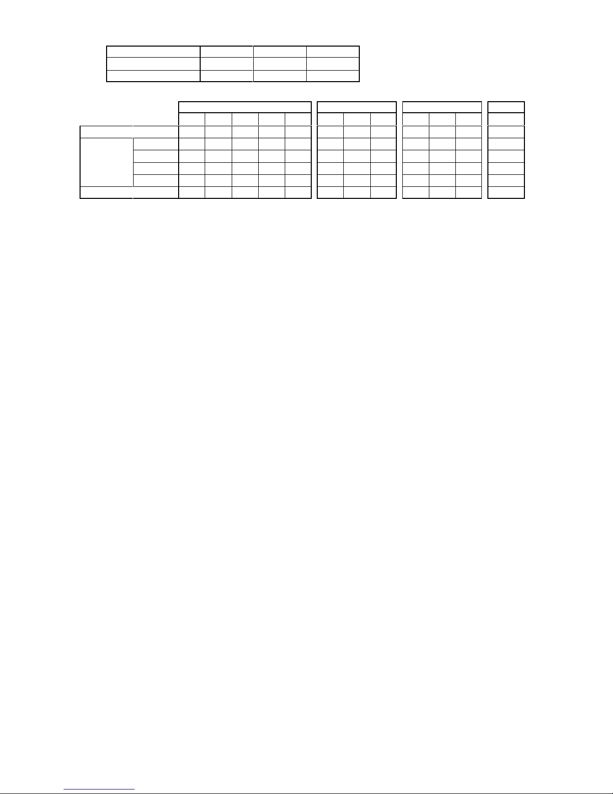
ELECTRICAL LOADS: Amps (230V 50Hz 1Ph) or A/Ph (400V 50Hz 3PhN)
WM (L) (E) 60 80 100
Fan Motor 0.4 0.4 0.5
Electric heater 5.2 7.2 9.2
MCU / MCU+ / MCUP MHPUL / MHPUE DCUE DHPUE
50 60 80 90 100 50 80 90 50 60 80 50
Fan motor 0.6 0.6 0.6 1.0 1.0 0.6 1.0 1.0 2.6 2.6 2.6 2.6
Compressor
nominal FLA
R407C 1Ph 8.3 10.2 10.9 15.0 - 8.3 10.9 15.0 10.5 11.8 14.8 10.5
R407C 3Ph 3.5 3.6 4.3 5.8 6.9 3.5 4.3 5.8 4.1 4.3 4.8 4.1
R22 1Ph 7.9 9.7 10.4 14.3 - 7.9 10.4 14.3 10.0 11.0 14.1 10.0
R22 3Ph 3.4 3.5 3.9 5.5 6.6 3.4 3.9 5.5 4.0 4.1 4.6 4.0
Crankcase heater ----- ---0.250.250.250.25
Page 9
-9-
FUSES / DISJONCTEURS / SICHERUNGEN (EN60269) - MCBs (EN60898)
1Ø - 230 V R407C / R22
FUSE RATING (A) / TAILLE DES DISJONCTEURS (A) / EMPFOHLENE SICHERUNG (A) (HRC Type)
MCU
MCU+
MCUP
WM (L) (E)
DCUE
WM (L) (E)
60 80 100 60 80 100
SHSHSH SHSHSH
501616---- 502525---602020---- 602525---80 - - 25 25 - - 80 - - 32 32 - 90 - - 32 32 32 32
MHPUL
MHPUE
WM L (E)
DHPUE
WM E
60 80 100 60 80 100
SHSHSH SHSHSH
501625---- 502532---80 - - 25 32 - 90----3250 (40)** R407C (R22)
S = No Electric Heating / Sans Batterie Electrique / Ohne Elektroheizung
H = + Electric Heaters / + Batterie Electrique / Mit Elektroheizung
H= 1.2 kW {WM 60 (L) (E)}, H = 1.7 kW {WM 80 (L) (E)}, H = 2.1 kW {WM100 (L) (E)}, @ 230V
3Ø - 400 V R407C / R22
FUSE RATING (A/Ø) / TAILLE DES DISJONCTEURS (A/Ph) / EMPFOHLENE SICHERUNG (A/Ph)
(HRC Type)
MCU
MCU+
MCUP
WM (L) (E)
DCUE
WM (L) (E)
60 80 100 60 80 100
SHSHSH SHSHSH
501616---- 501010---601616---- 601616---80 - - 16 16 - - 80 - - 20 20 - 90 - - 16 16 16 16
100----1616
MHPUL
MHPUE
WM L (E)
DHPUE
WM E
60 80 100 60 80 100
SHSHSH SHSHSH
501616---- 501616---80
-
-1620- -
90----1625
S = No Electric Heating / Sans Batterie Electrique / Ohne Elektroheizung
H = + Electric Heaters / + Batterie Electrique / Mit Elektroheizung
H= 1.2 kW {WM 60 (L) (E)}, H = 1.7 kW {WM 80 (L) (E)}, H = 2.1 kW {WM100 (L) (E)}, @ 230V
DCUE / MHPUE / DHPUE - WITH SEPARATE SUPPLIES
- AVEC ALIMENTATION SÉPARÉE
- MIT GETRENNTEN STROMVERSORGUNGEN
FUSE RATING / TAILLE DES DISJONCTEURS / EMPFOHLENE SICHERUNG (A, A/Ph)
INDOOR UNITS / INTÉRIEUR / INNERGERÄTE OUTDOOR UNITS / EXTÉRIEUR / AUSENGERÄTE
WM E S H Unit size 50 60 80 90
60 E 5 10 DCUE 1Ph A 25 25 32 80 E 5 10 MHPUE 1Ph A 16 - 25 32
100 E 5 16 DHPUE 1Ph A 25 - - -
DCUE 3Ph A/Ph 10 16 16 MHPUE 3Ph A/Ph 10 - 16 16
DHPUE 3Ph A/Ph 10 - - -
S = No Electric Heating / Sans Batterie Electrique / Ohne Elektroheizung
H = + Electric Heaters / + Batterie Electrique / Mit Elektroheizung
H= 1.2 kW (WM 60E), H = 1.7 kW (WM 80E), H = 2.1 kW (WM100 E), @ 230V
Page 10
-10-
ELECTRICAL DATA ~ R407C ( maximum indoor unit fan speed)
a) R407C: WM + MCU / MCU+ /MCUP
COOLING
27/C/19/C, 35//24/C
1Ph 230V 50Hz 3Ph 400V 50Hz
INPUT
FULL LOAD
CURRENT
SYSTEM MAX.
STARTING
CURRENT
INPUT
FULL LOAD
AMPS
SYSTEM MAX.
STARTING
CURRENT
WM MCU(+) kW AMPS AMPS kW A/PH A/PH
60 50 2.0 9.3 59 2.0 4.5 27
60 60 2.4 11.2 62 2.4 4.6 33
80 80
3.0 11.9 77 3.0 5.3 41
80 90
3.6 16.4 97 3.5 7.2 46
100 90
3.6 16.5 97 3.5 7.3 46
100 100
- - - 3.7 8.4 52
HEATING (230V 50Hz)
20
/C/12/C, 7/C/6/C
WM MCU MCU+ MCUP kW AMPS
60 ALL
1.2 5.2
80 ALL
1.7 7.2
100 ALL
2.1 9.2
b) R407C: WM (L) (E) + DCUE
COOLING
27/C/19/C, 35//24/C
1Ph 230V 50Hz 3Ph 400V 50Hz
INPUT
FULL LOAD
CURRENT
SYSTEM MAX.
STARTING
CURRENT
INPUT
FULL LOAD
AMPS
SYSTEM MAX.
STARTING
CURRENT
WM (L) (E) DCUE kW AMPS AMPS kW A/PH A/PH
60 50 2.5 13.8 60 2.5 7.4 24
60 60 2.9 15.1 70 2.9 7.6 24
80 80 3.3 18.1 79 3.3 8.1 27
HEATING (230V 50Hz)
20
/C/12/C, 7/C/6/C
WM (L) (E) DCUE kW AMPS
60 ALL 1.2 5.2
80 ALL 1.7 7.2
100 ALL 2.1 9.2
c) R407C: WM (L) (E) + MHPUL / MHPUE
COOLING
27
/C/19/C, 35//24/C
1Ph 230V 50Hz 3Ph 400V 50Hz
INPUT
FULL LOAD
AMPS
SYSTEM
MAX.
STARTING
CURRENT
INPUT
FULL LOAD
AMPS
SYSTEM
MAX.
STARTING
CURRENT
WM (L) (E) MHPUL (E) kW AMPS AMPS kW A/PH A/PH
60 50 2.0 9.3 59 2.0 4.5 27
80 80 3.0 12.3 77 2.9 5.7 41
100 90 3.6 16.5 97 3.5 7.3 46
HEATING
(230V 50Hz)
20
/C/12/C, 7/C/6/C
1Ph 230V 50Hz 3Ph 400V 50Hz
INPUT
FULL LOAD
AMPS
SYSTEM
MAX.
STARTING
CURRENT
INPUT
FULL LOAD
AMPS
SYSTEM
MAX.
STARTING
CURRENT
kW AMPS AMPS kW A/PH A/PH
WM (L) (E) MHPUL (E) S H S H S H S H
60 50 2.2 3.4 9.3 14.5 64 2.2 3.4 4.5 9.7 32
80 80 2.9 4.6 12.3 19.5 84 2.9 4.6 5.7 12.9 48
100 90 2.8 4.9 16.5 25.7 106 2.8 4.9 7.3 16.5 54
S = standard unit (no heaters) H = + Electric heaters
Page 11
-11-
d) R407C: WM (L) (E) + DHPUE
COOLING
27
/C/19/C, 35//24/C
1Ph 230V 50Hz 3Ph 400V 50Hz
INPUT
FULL LOAD
CURRENT
SYSTEM MAX.
STARTING
CURRENT
INPUT
FULL LOAD
AMPS
SYSTEM
MAX.
STARTING
CURRENT
WM (L) (E) DHPUE kW AMPS AMPS kW A/PH A/PH
60 50 2.5 13.8 60 2.5 8.1 24
HEATING
(230V 50Hz)
20
/C/12/C, 7/C/6/C
1Ph 230V 50Hz 3Ph 400V 50Hz
INPUT
FULL LOAD
AMPS
SYSTEM
MAX.
STARTING
CURRENT
INPUT
FULL LOAD
AMPS
SYSTEM
MAX.
STARTING
CURRENT
kW AMPS AMPS kW A/PH A/PH
WM (L) (E)DHPUESHSH SHSH
60 50 2.5 3.7 13.8 19.0 66 2.5 3.7 8.1 13.3 30
S = standard unit (no heaters) H = + Electric heaters
Page 12
-12-
ELECTRICAL DATA ~ R22 ( maximum indoor unit fan speed)
e) R22: WM + MCU / MCU+ /MCUP
COOLING
27/C/19/C, 35//24/C
1Ph 230V 50Hz 3Ph 400V 50Hz
INPUT
FULL LOAD
CURRENT
SYSTEM MAX.
STARTING
CURRENT
INPUT
FULL LOAD
AMPS
SYSTEM MAX.
STARTING
CURRENT
WM MCU(+) kW AMPS AMPS kW A/PH A/PH
60 50 2.0 8.9 59 2.0 4.4 27
60 60 2.4 10.7 62 2.4 4.5 33
80 80 3.0 11.4 77 3.0 4.9 41
80 90 3.6 15.7 97 3.6 6.9 46
100 90 3.6 15.8 97 3.6 7.0 46
100 100 - - - 3.7 8.1 52
HEATING (230V 50Hz)
20
/C/12/C, 7/C/6/C
WM MCU MCU+ MCUP kW AMPS
60 ALL 1.2 5.2
80 ALL 1.7 7.2
100 ALL 2.1 9.2
f) R22: WM (L) (E) + DCUE
COOLING
27/C/19/C, 35//24/C
1Ph 230V 50Hz 3Ph 400V 50Hz
INPUT
FULL LOAD
CURRENT
SYSTEM MAX.
STARTING
CURRENT
INPUT
FULL LOAD
AMPS
SYSTEM MAX.
STARTING
CURRENT
WM (L) (E) DCUE kW AMPS AMPS kW A/PH A/PH
60 50 2.5 13.3 60 2.5 7.3 24
60 60 2.9 14.3 70 2.9 7.4 24
80 80 3.3 17.4 79 3.3 7.9 27
HEATING (230V 50Hz)
20
/C/12/C, 7/C/6/C
WM DCUE kW AMPS
60 ALL 1.2 5.2
80 ALL 1.7 7.2
100 ALL 2.1 9.2
g) R22: WM (L) (E) + MHPUL / MHPUE
COOLING
27
/C/19/C, 35//24/C
1Ph 230V 50Hz 3Ph 400V 50Hz
INPUT
FULL LOAD
AMPS
SYSTEM
MAX.
STARTING
CURRENT
INPUT
FULL LOAD
AMPS
SYSTEM
MAX.
STARTING
CURRENT
WM (L) (E) MHPUL (E) kW AMPS AMPS kW A/PH A/PH
60 50 2.0 8.9 59 2.0 4.4 27
80 80 3.0 11.8 77 3.0 5.3 41
100 90 3.6 15.8 97 3.6 7.0 46
HEATING
(230V 50Hz)
20
/C/12/C, 7/C/6/C
1Ph 230V 50Hz 3Ph 400V 50Hz
INPUT
FULL LOAD
AMPS
SYSTEM
MAX.
STARTING
CURRENT
INPUT
FULL LOAD
AMPS
SYSTEM
MAX.
STARTING
CURRENT
kW AMPS AMPS kW A/PH A/PH
WM (L) (E) MHPUL (E) S H S H S H S H
60 50 2.2 3.4 8.9 14.1 64 2.2 3.4 4.4 9.6 32
80 80 2.9 4.6 11.8 19.0 84 2.9 4.6 5.3 12.5 48
100 90 2.8 4.9 15.8 25.0 106 2.8 4.9 7.0 16.2 54
S = standard unit (no heaters) H = + Electric heaters
Page 13
-13-
h) R22: WM (L) (E) + DHPUE
COOLING
27
/C/19/C, 35//24/C
1Ph 230V 50Hz 3Ph 400V 50Hz
INPUT
FULL LOAD
CURRENT
SYSTEM MAX.
STARTING
CURRENT
INPUT
FULL LOAD
AMPS
SYSTEM
MAX.
STARTING
CURRENT
WM (L) (E) DHPUE kW AMPS AMPS kW A/PH A/PH
60 50 2.5 13.3 60 2.5 7.3 24
HEATING
(230V 50Hz)
20
/C/12/C, 7/C/6/C
1Ph 230V 50Hz 3Ph 400V 50Hz
INPUT
FULL LOAD
AMPS
SYSTEM
MAX.
STARTING
CURRENT
INPUT
FULL LOAD
AMPS
SYSTEM
MAX.
STARTING
CURRENT
kW AMPS AMPS kW A/PH A/PH
WM (L) (E)DHPUESHSH SHSH
60 50 2.5 3.7 13.3 18.5 66 2.5 3.7 7.3 12.5 30
S = standard unit (no heaters) H = + Electric heaters
Page 14
-14-
Page 15
-15-
INSTALLATION
HANGING RAIL
FIXING THE HANGING RAIL
HANGING THE CHASSIS
Page 16
-16-
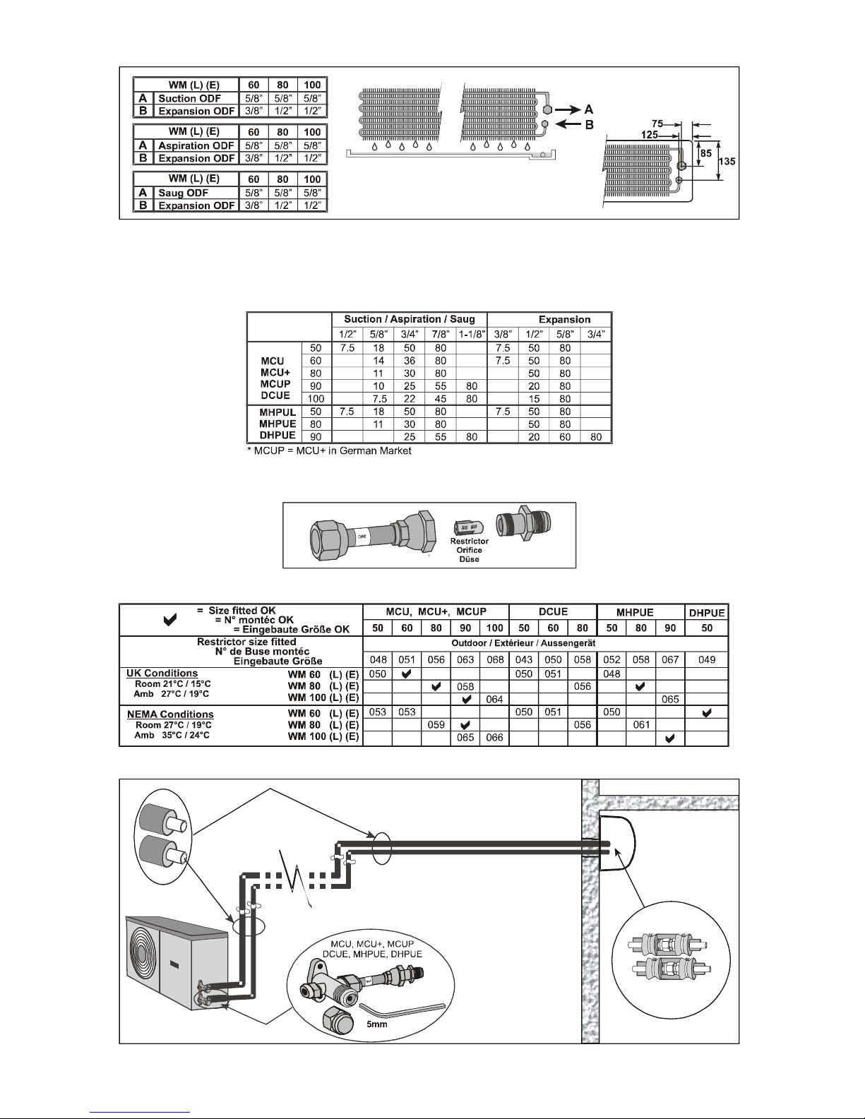
REFRIGERATION PIPEWORK / TUYAUTERIES / ROHRLEITUNGEN
MAXIMUM EQUIVALENT PIPE LENGTHS (M)
LONGUEURS EQUIVALENTES TUYAUTERIES MAXI (M)
MAXIMAL ÄQUIVALENTE ROHRLEITUNGSLÄNGEN (M)
RESTRICTOR ASSEMBLY / ASSEMBLAGE DE L’ACCURATEUR / DÜSENVORRICHTUNGEN
RESTRICTOR SIZES / NUMÉRO DES BUSES DE DÉTENTE / DÜSENGRÖßE
PIPEWORK CONNECTION / RACCORDEMENT DES TUYAUTERIES / ROHRLEITUNGEN
Page 17
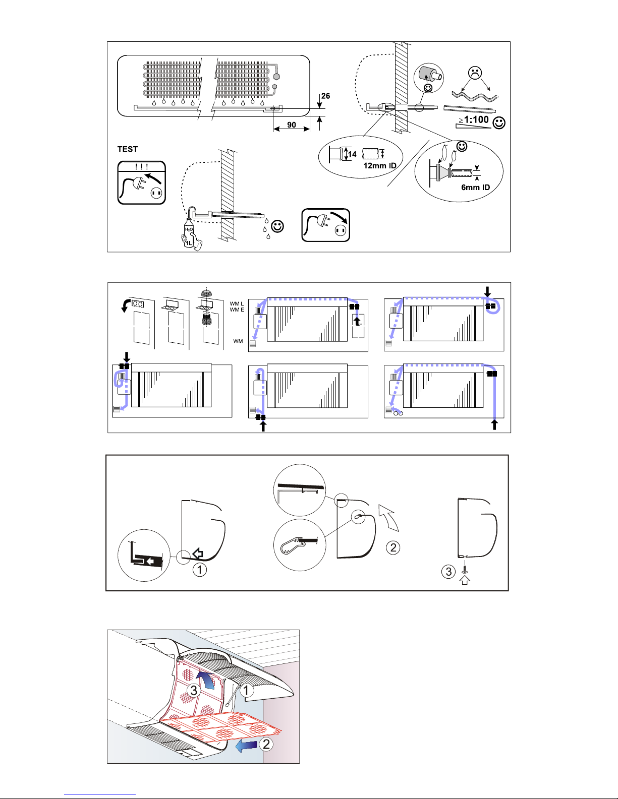
-17-
GRAVITY DRAIN
CABLE ROUTING
FITTING THE CASE
FITTING THE FILTERS
Page 18
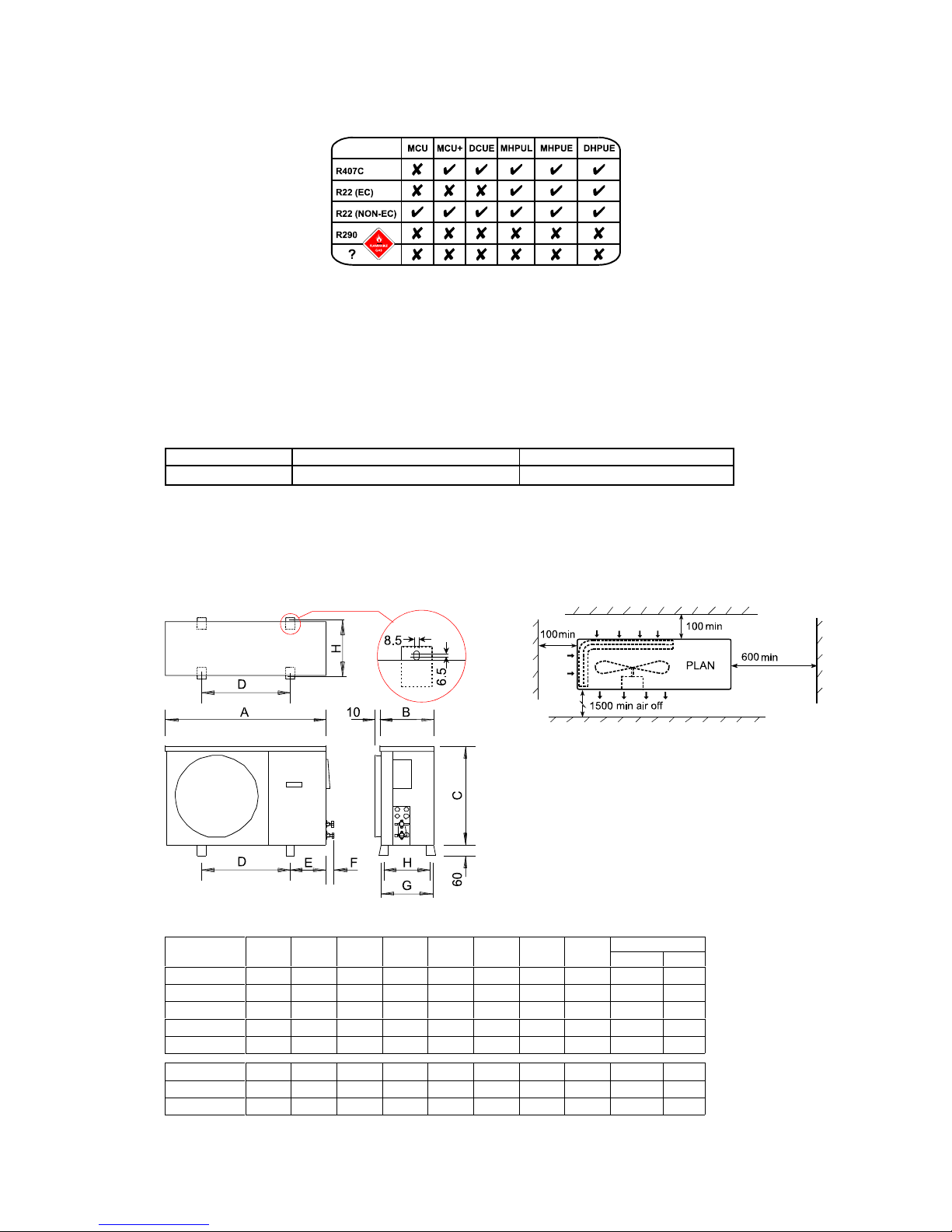
-18-
INSTALLATION OF 550 SERIES CONDENSING UNITS AND 551 SERIES HEAT PUMP OUTDOOR
UNITS
MCU = standard condensing unit MCU+ = standard condensing unit + FSC + LP MHPUL(E) = electronic heat pump outdoor unit
MCUP = German description for MCU+ = standard condensing unit + FSC + LP
Units are supplied with loose restrictors which may be required, depending on the indoor unit it is matched with; refer to page
16.
The installer will require:
2 flare spanners for securing the flare fittings Refrigeration quality pipework Evacuating pump
A 5 mm Allen key to open the valves. Insulation Refrigerant and polyolester oil
Kits are more easily fitted prior to mounting the unit.
Units are designed to stand on a flat surface. If the unit is to be wall mounted the following kits are available:(Marstair Ltd cannot accept liability for installers own mounting arrangements).
Model MCU(+) 50 - 80 / MHPUL(E) 50 MCU(+) 90 - 100 / MHPUL (E) 80 - 90
Mounting Bracket Kit
55021100 55021101
MOUNTING: MCU(+) 50 - 100 and MHPUL(E) 50 - 90
Whether floor or wall mounted, it is essential that the mounting surface is capable of supporting the unit weight.
Leave space around the unit for air circulation and access for installation and maintenance.
All dimensions mm
MODEL ABCDEFGH
Weight (kg)
1 Ph 3
MCU(+) 50
1000 300 660 570 213 60 333 308 64 62
MCU(+) 60
1000 300 660 570 213 60 333 308 65 63
MCU(+) 80
1000 300 660 570 213 60 333 308 66 64
MCU(+) 90
1000 350 760 495 250 70 383 358 76 73
MCU(+) 100
1000 350 760 495 250 70 383 358 -- 81
MHPUE 50
1000 300 660 570 213 60 333 308 64 62
MHPUE 80
1000 350 760 495 250 70 383 358 75 72
MHPUE 90
1000 350 760 495 250 70 383 358 77 75
Page 19
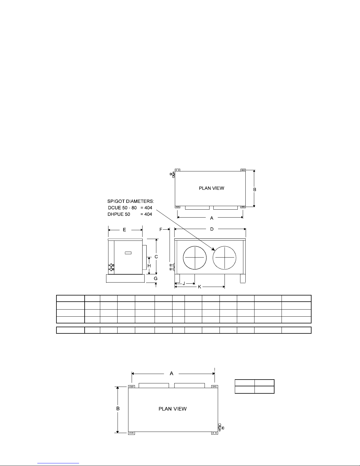
-19-
}
for use on 1Ph systems, particularly on long pipe runs.
542 SERIES DUCTED CONDENSING UNITS
These units have electronic fan speed control, start delay timer, HP and LP switches and a contactor fitted as
standard; stabilizing brackets are supplied loose .
It is generally preferable to fit the following kits (if applicable), prior to mounting the unit:-
i) PTC kit (Positive Temperature Coefficient resistor)
ii) CSR kit(Capacitor Start Relay).
iii) Isolator.
iv) Overload kit (single phase units only; standard on three phase units).
v) Wall mounting kit.
Consideration should be given to the following, prior to mounting, but should not be fitted until the unit is in
position:i) Flexible ductwork.
ii) Plenums (return/discharge).
iii) Grilles (return/discharge).
A bag containing 4 suspension brackets, 8 screws and 2 cable glands is supplied taped to the base of the unit next
to the compressor.
MOUNTING
Units are supplied with a polystyrene packing piece supporting the blower assembly, this MUST be removed prior to
commissioning.
Ducted units are designed to be hung on a wall (brackets available as a kit), suspended from a ceiling (installer
supplied fittings), or to stand on a flat surface. Whichever method is used it is essential that the mounting surface is
capable of supporting the unit's weight.
DIMENSIONS
All dimensions mm
Model A B C D E F G H J K Spigot Ø Weight (kg)
DCUE 50
1100 510 560 1174 490 65 65 240 392 865 404 81
DCUE 60
1100 510 560 1174 490 65 65 240 392 865 404 81
DCUE 80
1100 510 560 1174 490 65 65 240 392 865 404 84
DHPUE 50
1100 510 560 1174 490 65 120 240 392 865 404 95
FLOOR MOUNTING
Using the appropriate side of the packing carton as a template, (centres marked A), mark out and drill 4 holes to suit
maximum M8 bolts. Secure the unit to the floor. Discard the 4 stabilizing brackets.
A (mm) B (mm)
1100 510
Fig. 1
Page 20
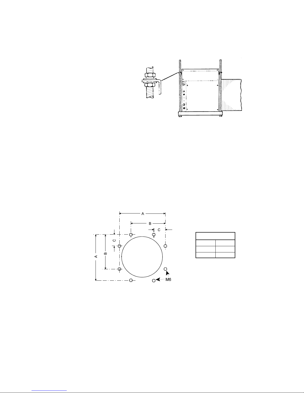
-20-
SUSPENSION MOUNTING
The installer must supply 4 x M8 threaded rods with 16 nuts and washers to suit.
IMPORTANT: The stabilizing brackets provided MUST be used when suspending a unit.
Fit the stabilizing brackets to the top corners of the backpanel and front face using the No. 10 screws provided, (2
per bracket).
If these brackets are omitted the unit will be subject to unacceptable movement on compressor start.
Where long drops of M8 rod are used, it is
advisable to incorporate flexible pipes in the
suction and expansion lines.
Using the template printed on the side of the
packing carton, (centres marked A), mark out
the ceiling and drill 4 holes to suit M8 screwed
rod, (see Fig. 1).
Raise the unit to the required height and pass
the screwed rods through the mounting holes in
the units feet and stabilizing brackets.
Secure the unit with a nut and washer on either
side of each stabilizing bracket and two nuts
and washers underneath each foot mounting hole,
(Fig. 2).
WALL MOUNTING
Wall mounting brackets are available as an optional kit (53200407).
DUCTWORK
Each unit is supplied with 404mm Ø (16" Ø) air inlet and discharge spigots.
These may be used for connecting installers ducting or with the optional duct, plenum and grille kits (refer to the kit
instruction for installation). The front face of the units are fitted with M6 rivnuts to accept square ducting (shown
below). Maximum flange width is 25mm and fixing holes should be central within them.
NOTE: It is essential that ducting is adequately insulated to prevent sweating.
An insulation thickness of at least 45mm is recommended.
Dimensions (mm)
A 450
B 350
C 100
PIPE SIZING
1. To maximise performance, pipe runs should be kept as short as possible, avoiding sharp bends. However,
individual pipe runs to a maximum of 80m, including 20m lift, are permissible provided good refrigeration practice
is followed.
Published performance duties are based on 7.5m pipe runs. Correctly sized pipes for each installation, and fitting
the correct expansion orifice (restrictor) will result in no significant loss of capacity on extended pipe runs.
a) Pipe sizes are based on:-
Minimum of 3.8 m/s (750 fpm) suction gas velocity for horizontal or downflow.
Minimum of 7.6 m/s (1500 fpm) suction gas velocity for upflow.
Maximum of 15.2 m/s (3000 fpm) suction gas.
b) Where vertical risers exceed 3m, oil traps must be formed in the pipe. This will help ensure that oil returns to
the compressor. Typically fit an oil trap every 3m with a trap at the bottom of the riser.
2. Add polyolester oil as tabled on page 27; preferably by slowly pumping into the suction side with the unit running,
after charging the system.
Fig. 2
Page 21
-21-
3. The maximum pipe lengths to be used for each pipe size and outdoor unit are shown on page 16. Use of
these sizes and lengths is recommended in order to achieve optimum system performance. Smaller sizes may
be used, but at the risk of loss of performance.
4. In calculating equivalent lengths of pipe runs, the effect of bends and fittings must be taken into account. The table
below covers the fittings most likely to be encountered in this type of installation. The equivalent lengths of all the
fittings in a particular pipe run must be added together and the total added to the actual length of pipe in the run,
in order to calculate the total equivalent length.
5. Use the shortest possible route, avoiding sharp bends.
6. Fully insulate both the suction and expansion lines, including the expansion device, since both lines may sweat.
Pipe Size (outside diameter in inches)
Fitting 3/8 1/2 5/8 3/4 7/8 1-1/8
45
/ Bend
0.12 0.15 0.18 0.21 0.24 0.3
90
/ Bend R/d = 1
0.37 0.43 0.49 0.55 0.61 0.79
90
/ Bend R/d = 1.5
0.24 0.27 0.30 0.37 0.43 0.52
180
/ Bend C/d = 1.5
0.73 0.91 1.10 1.28 1.46 1.83
180
/ Bend C/d = 2.5
0.46 0.55 0.64 0.76 0.85 1.07
90
/ Elbow
0.67 0.85 1.04 1.25 1.46 1.89
R = Radius of bend d = Diameter of tube C = Centres of bend
FITTING LOSSES, in equivalent straight lengths of pipe (m)
PIPE CONNECTIONS
Pipework is terminated with flare nut connectors, adjacent to the access panel.
Units are supplied with the following male flare connections (sizes in inches):-
Model
Size
WM (L) (E) MCU / MCU+ / M CUP / DCUE MHPUL (E)
60 80 100 50 60 80 90 100 50 80 90
Suction
5/8 5/8 5/8 1/2 5/8 5/8 5/8 3/4 1/2 5/8 3/4
Expansion
3/8 1/2 1/2 3/8 3/8 1/2 1/2 1/2 3/8 1/2 1/2
NOTE: Ensure that both service valves on the outdoor unit are closed (IN, fully clockwise) before commencing
installation.
Indoor units have a low pressure holding charge of nitrogen, which may be released into the atmosphere without damage
to the environment. This should be done prior to making pipework connections.
RESTRICTORS
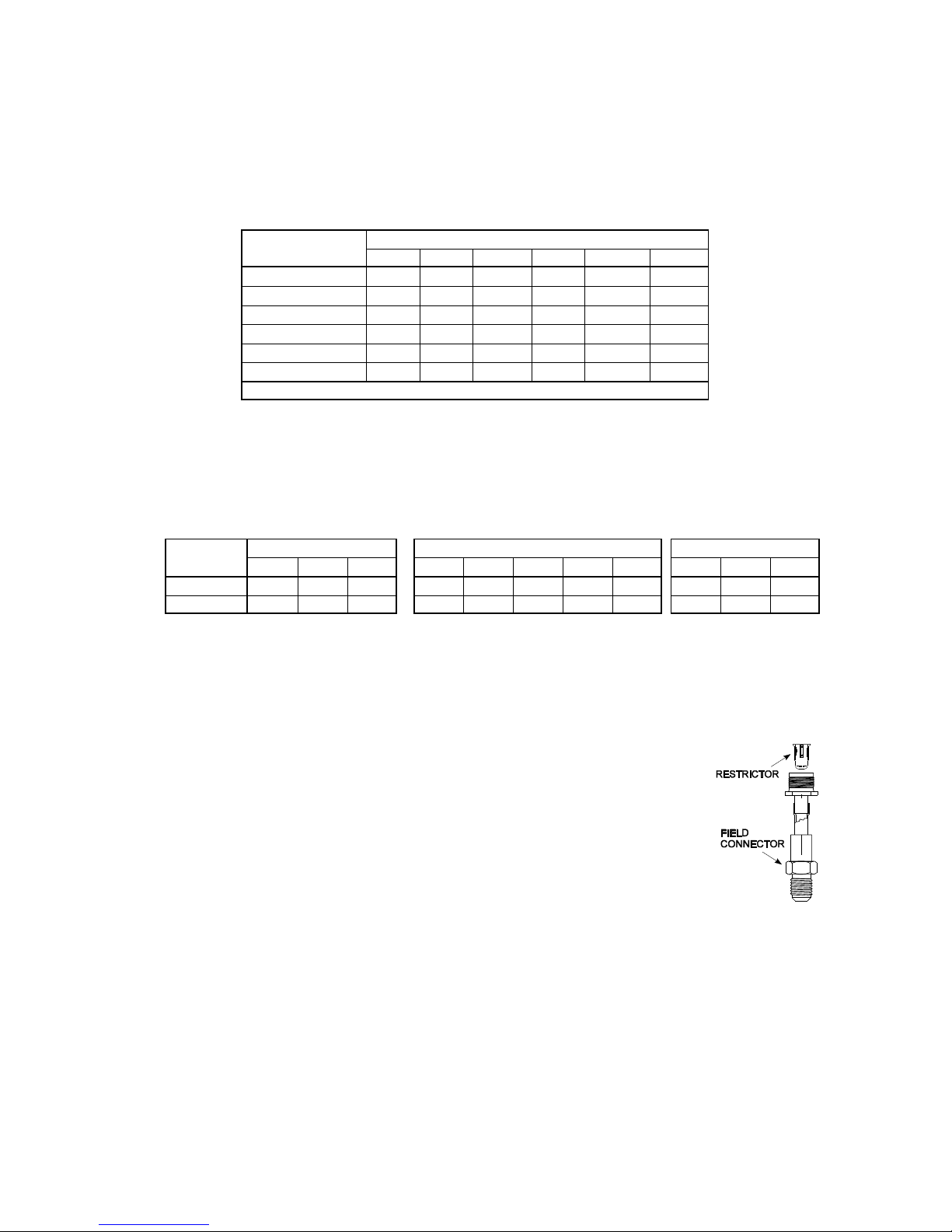
Outdoor units are supplied with restrictors fitted; refer to page 16 for any restrictor changes;
those ticked do not require changing. Where appropriate, the alternative restrictor is supplied
with either the indoor or the outdoor unit.
For units needing a change of restrictor, replace the restrictor in the outdoor unit by:
a. Completely removing the expansion assembly from the outdoor unit.
b. Split the expansion assembly in the middle.
c. Remove the existing restrictor.
d. Drop the new restrictor vertically downwards into the field connector.
e. Reassemble in the vertical plane (field connector lowest) and refit the expansion
assembly to the outdoor unit.
ELECTRICAL SUPPLY
1. Mains, control and interconnecting cables must be supplied and fitted by the installer. Follow local and national wiring
regulations.
2. Cables must be size compatible with the recommended system fuse size.
3. Position an isolator switch within easy reach of the indoor unit.
4. Ensure the equipment is earthed.
Page 22

-22-
INTERCONNECTING WIRING
Interconnecting wiring diagrams are shown on pages 38 to 40.
WM E SYSTEMS: An EMC gland kit (part number 55200301) MUST be used if the system is:-
C Hard wired to a handset (1 data cable)
One termination gland can be used for up to 3 cables. Each
• Fitted with a remote temperature sensor (1 data cable) cable is four core screened cable, available from Marstair
in
100m
• A heat pump (1 data cable) rolls, part number 00526077.
C BMS controlled (2 data cables)
C Networked (2 data cables)
Details of the kit are on page 46.
WM E MATCHED WITH EITHER MHPUE, OR DCUE
It is recommended that these systems should have a supply taken to the outdoor / ducted unit AND a separate supply
taken to the indoor unit, which in many cases can be from a domestic 13/16 Amp socket (see fuse tables page 10).
Communication cables should be screened 2 core (max. 0.75mm
2
) non polarised, grounded at both ends using the
clamps provided.
DO NOT use coaxial or mineral insulated cables.
ALL OTHER SYSTEMS:
Cables should be run to the outdoor unit with interconnecting cables run back to the indoor unit.
OUTDOOR UNIT WIRING
Cable entry for the outdoor unit electrics is through the cabinet to a terminal block.
Electromechanical condensing units (MCU) are supplied wired for low fan speed, which is suitable for temperate climates.
If continuous running is expected at ambient temperatures of 35°C or higher, change to high speed by interchanging the
black and red wires, i.e. black to fused terminal, red to terminal 4.
MCU+, MHPUE, DCUE and DHPUE are supplied wired to the high speed fan tapping via the head pressure controller
to give maximum control. Ensure that all connections are secure and that both units are earthed.
3Ph COMPRESSOR ROTATION
On 3 Ph units it is possible for the compressor to run backwards. This becomes obvious on start up: the compressor will
not develop a normal running pressure differential and the top will not become warm. It may be excessively noisy.
To reverse the rotation, switch off the mains power, identify the phase supplying the indoor unit, and exchange the other
two incoming supply phases.
CAUTION: if one of the phases changed is the phase supplying the indoor unit, damage will occur.
DATA PLATES
Because of the ability to mix-match indoor and outdoor units, the data plate only gives information on outdoor units. To
obtain the system details, input power and currents from indoor and outdoor units should be added together. Data plates
show basic units with electric heater kit loads shown separately.
FIRE LINK
Electromechanical models: In order to automatically switch off the fan in the event of a fire, fit an external switch (240V,
3A, closed to run, volt free contact) between terminal block terminal 2 and the Marstair remote control terminal L.
This switch should be operated by the building's fire alarm or BMS system - see wiring diagram page 29.
Electronic models: ‘L’ units: see wiring diagram page 30; ‘E’ units: see wiring diagram page 31.
Remove the black wire from the bottom terminal of the fuse (between fuse and motor) and place in series an external
switch (240V, 3A, closed to run, volt-free contact). This switch should be operated by the fire alarm or BMS.
--o--o--O--O--O--o--o–
Page 23
-23-
Page 24
-24-
Page 25
-25-
WM L indoor units are supplied with a remote controller, wall mounting bracket and two batteries.
The controller operates remotely by infrared signals and the bracket may be used to park the controller for convenience.
Slide open the front cover: press down on the top at the marked area and push off the cover. Insert the batteries ensuring
correct polarity. The display will blank and reset.
Replace the cover by sliding into position.
Operating instructions are on page 16.
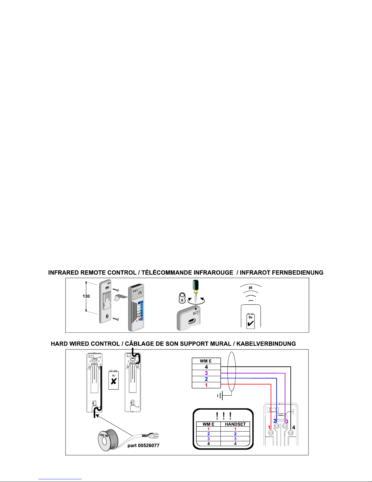
WM E REMOTE CONTROLLER.
WM E indoor units are supplied with a remote controller, wall mounting bracket, PP3 (9 volt) battery, screws and wall
plugs.
The controller operates either remotely by infrared signals, when the wall mounting bracket may be used to park the
controller for convenience, or may be hard wired to the unit (via the wall mounting bracket) in applications where infrared
is inappropriate, e.g., high lighting level, no direct line of sight etc..
1. Infrared operation
Open the battery cover at the bottom rear of the controller by sliding out and hinging up, push the polarised connector
onto the battery, slot into the controller and close the cover. The controller is now ready for operation as shown on
page 50.
For convenience, the wall mounting bracket may be secured to a wall and used to park the controller.
2. Hard wired
Use four core screened cable (available from MARSTAIR in 100m drums, part number 00526077). The screen should
be clamped to ground in the WM E unit but NOT connected at the wall bracket end.
NOTE: Great care should be taken to ensure that the wiring is correct, refer to the diagram and table below.
The cable should be connected prior to mounting the bracket, taking great care to ensure that the 4 contact blades
remain free to exert spring pressure on the handset terminals.
Secure the bracket to the wall by drilling two 6mm diameter holes in the positions shown, inserting the wall plugs and
securing with the two screws provided.
Attach the controller to the bracket ensuring that it is pushed down firmly.
If required, the controller may be locked into position by rotating the cam at the top of the bracket with a small
screwdriver. The controller is now ready for operating as stated in the user handbook.
The controller does not require a battery when this method is used.
Page 26
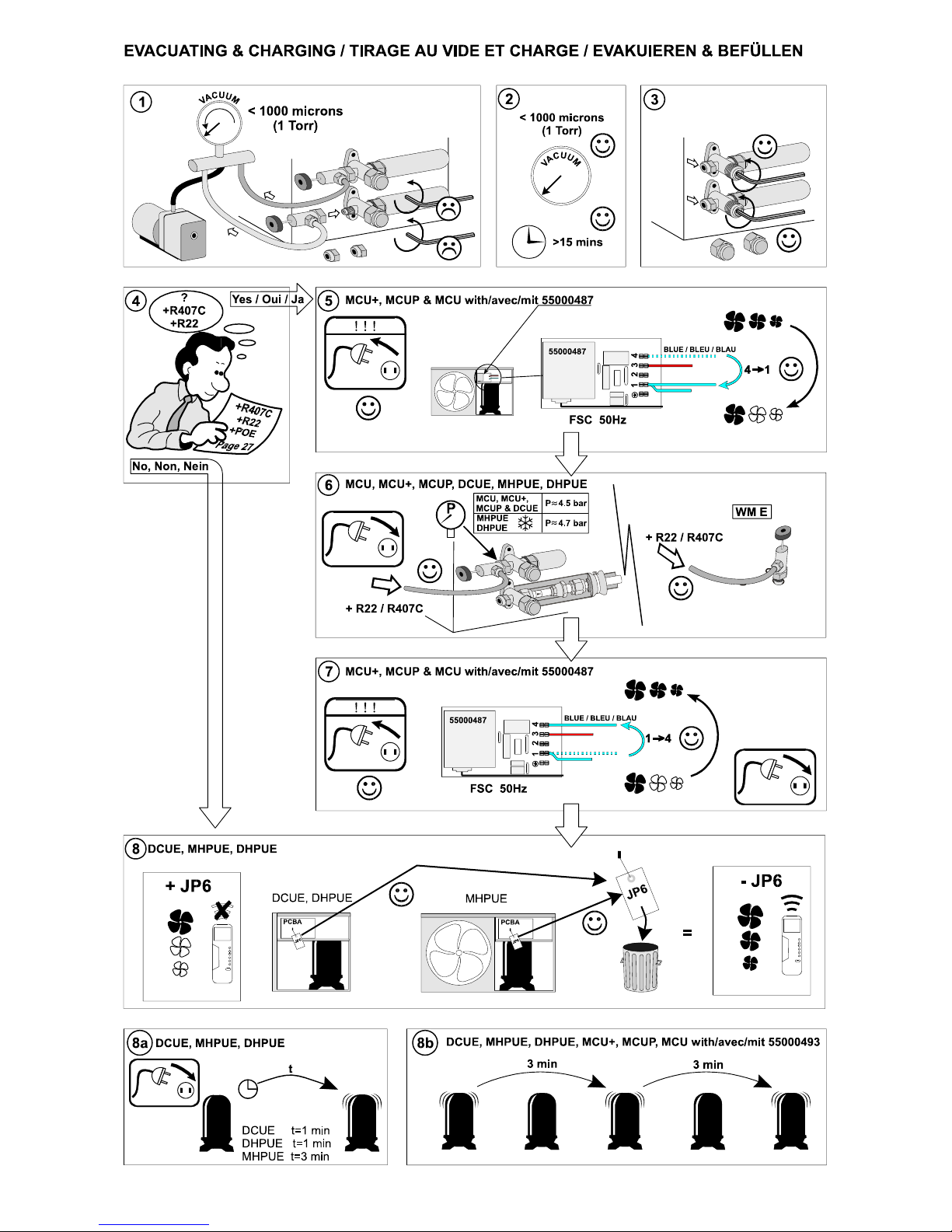
-26-
Page 27
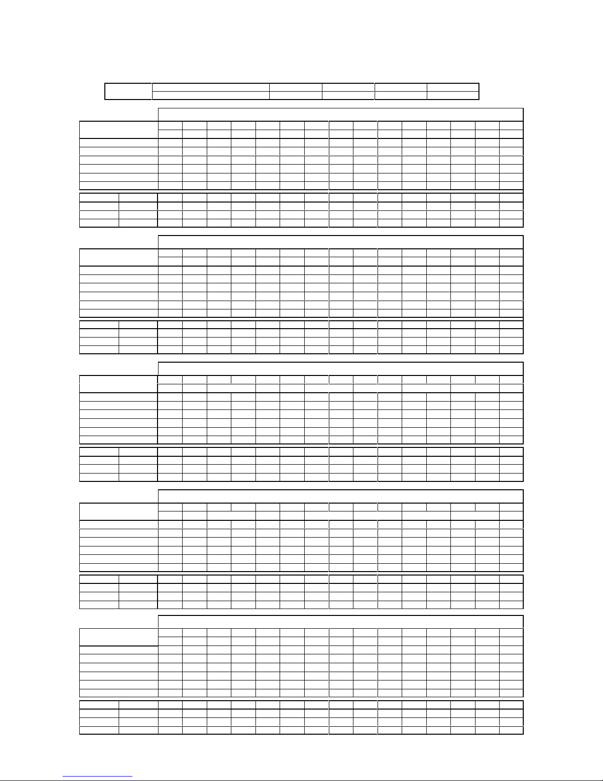
-27-
+R407C ? / +R22 ? / +POE ? (g)
Add extra refrigerant and polyolester (POE) oil to systems as shown below . Figures assume pipe sizes as shown on page 16.
Ajouter du réfrigérant et de l’huile polyolester (POE) selon le tableau ci-dessous. Les tableaux sont basés sur le respect des
diamètres de tuyauteries montrés page 16.
Zustätzliches Kältemittel und Öl Polyolester (POE) wie unten angegeben dem System zufügen. Die Abbildungen nehmen
Leitungsgrößen wie auf Seite 16 gezeigt an.
>8m
Expansion Ø 3/8" 1/2" 5/8" 3/4"
+R22 / +R407C (g/m) 16 30 48 68
+R407C UK
LENGTH OF EXPANSION LINE (m) / LONGUEUR DE LA LIGNE EXPANSION (m) / LÄNGE DER EXPANSIONSLEITUNG (m)
WM (L) (E)
MCU, MCU+< = 81520253035404550556065707580
MCUP, DCUE
R407C R407C R407C R407C R407C R407C R407C R407C R407C R407C R407C R407C R407C R407C R407C
60 50 175 375 525 675 825 975 1125 1275 1425 1550 2625 2850 3100 3325 3550
60 60 0 225 375 525 675 800 950 1750 2000 2250 2450 2700 2925 3150 3400
80 80 125 350 500 625 775 1400 1650 1875 2100 2350 2575 2825 3050 3275 3525
80 90 325 525 675 1125 1375 1600 1850 2075 2300 2550 2775 3000 4575 4925 5250
100 90 150 350 500 950 1200 1425 1675 1900 2125 2375 2600 2825 4400 4750 5075
100 100 0 225 575 825 1050 1300 1525 1750 2000 3250 3575 3925 4275 4600 4950
WM L (E) MHPUL (E) R407C R407C R407C R407C R407C R407C R407C R407C R407C R407C R407C R407C R407C R407C R407C
60 50 250 450 600 750 900 1050 1200 1350 1500 1650 2700 2925 3175 3400 3625
80 80 525 750 900 1025 1175 1800 2050 2275 2500 2750 2975 3225 3450 3675 3925
100 90 0 225 375 825 1050 1300 1525 1750 2000 2225 2450 2700 4275 4600 4950
+R407C NEMA
LENGTH OF EXPANSION LINE (m) / LONGUEUR DE LA LIGNE EXPANSION (m) / LÄNGE DER EXPANSIONSLEITUNG (m)
WM (L) (E)
MCU, MCU+< = 81520253035404550556065707580
MCUP, DCUE
R407C R407C R407C R407C R407C R407C R407C R407C R407C R407C R407C R407C R407C R407C R407C
60 50 175 375 525 675 825 975 1125 1275 1425 1550 2625 2850 3100 3325 3550
60 60 0 225 375 525 675 800 950 1750 2000 2250 2450 2700 2925 3150 3400
80 80 125 350 500 625 775 1400 1650 1875 2100 2350 2575 2825 3050 3275 3525
80 90 325 525 675 1125 1375 1600 1850 2075 2300 2550 2775 3000 4575 4925 5250
100 90 150 350 500 950 1200 1425 1675 1900 2125 2375 2600 2825 4400 4750 5075
100 100 0 225 575 825 1050 1300 1525 1750 2000 3250 3575 3925 4275 4600 4950
WM L (E) MHPUL (E) R407C R407C R407C R407C R407C R407C R407C R407C R407C R407C R407C R407C R407C R407C R407C
60 50 350 550 700 850 1000 1150 1300 1450 1600 1750 2800 3025 3275 3500 3725
80 80 700 925 1025 1200 1350 1975 2225 2450 2675 2925 3150 3400 3625 3850 4100
100 90 0 225 375 825 1050 1300 1525 1750 2000 2225 2450 2700 4275 4600 4950
+R22 UK
LENGTH OF EXPANSION LINE (m) / LONGUEUR DE LA LIGNE EXPANSION (m) / LÄNGE DER EXPANSIONSLEITUNG (m)
WM (L) (E)
MCU, MCU+< = 81520253035404550556065707580
MCUP, DCUE
R22 R22 R22 R22 R22 R22 R22 R22 R22 R22 R22 R22 R22 R22 R22
60 50 250 450 600 750 900 1050 1200 1350 1500 1650 2700 2925 3175 3400 3625
60 60 100 325 475 625 775 900 1050 1850 2100 2325 2550 2800 3025 3250 3500
80 80 200 425 575 725 875 1500 1725 1950 2200 2425 2650 2900 3125 3350 3600
80 90 425 625 775 1225 1475 1700 1950 2175 2400 2650 2875 3100 4675 5025 5350
100 90 475 675 825 1275 1525 1750 1975 2225 2450 2675 2925 3150 4725 5075 5400
100 100 0 225 575 825 1050 1300 1525 1750 2000 3250 3575 3925 4275 4600 4950
WM L (E) MHPUL (E) R22 R22 R22 R22 R22 R22 R22 R22 R22 R22 R22 R22 R22 R22 R22
60 50 200 400 550 700 850 1000 1150 1275 1425 1575 2650 2875 3100 3350 3575
80 80 475 675 825 975 1125 1750 1925 2225 2450 2675 2925 3150 3400 3625 3850
100 90 0 225 375 825 1050 1300 1525 1750 2000 2225 2450 2700 4275 4600 4950
+R22 NEMA
LENGTH OF EXPANSION LINE (m) / LONGUEUR DE LA LIGNE EXPANSION (m) / LÄNGE DER EXPANSIONSLEITUNG (m)
WM (L) (E)
MCU, MCU+< = 81520253035404550556065707580
MCUP, DCUE
R22 R22 R22 R22 R22 R22 R22 R22 R22 R22 R22 R22 R22 R22 R22
60 50 150 350 500 650 800 950 1100 1250 1400 1550 2600 2825 3075 3300 3525
60 60 100 325 475 625 775 900 1050 1850 2100 2325 2550 2800 3025 3250 3500
80 80 200 425 575 725 875 1500 1725 1950 2200 2425 2650 2900 3125 3350 3600
80 90 425 625 775 1225 1475 1700 1950 2175 2400 2650 2875 3100 4675 5025 5350
100 90 475 675 825 1275 1525 1750 1975 2225 2450 2675 2925 3150 4725 5075 5400
100 100 0 225 575 825 1050 1300 1525 1750 2000 3250 3575 3925 4275 4600 4950
WM L (E) MHPUL (E) R22 R22 R22 R22 R22 R22 R22 R22 R22 R22 R22 R22 R22 R22 R22
60 50 300 500 650 800 950 1100 1250 1375 1525 1675 2750 2975 3200 3450 3675
80 80 650 850 1000 1150 1300 1925 2150 2400 2625 2850 3100 3325 3575 3800 4025
100 90 0 225 375 825 1050 1300 1525 1750 2000 2225 2450 2700 4275 4600 4950
+POE OIL
LENGTH OF EXPANSION LINE (m) / LONGUEUR DE LA LIGNE EXPANSION (m) / LÄNGE DER EXPANSIONSLEITUNG (m)
WM (L) (E)
MCU, MCU+< = 81520253035404550556065707580
MCUP, DCUE
POE POE POE POE POE POE POE POE POE POE POE POE POE POE POE
60 50 0 25 50 50 50 75 75 100 100 100 175 200 225 225 250
60 60 0 25 25 25 50 50 75 125 150 150 175 200 200 225 250
80 80 0 25 25 50 50 100 125 125 150 175 175 200 225 225 250
80 90 25 50 50 75 100 125 125 150 175 175 200 225 325 350 375
100 90 0 25 25 75 75 100 125 125 150 175 175 200 325 350 375
100 100 0 25 50 50 75 100 100 125 150 225 250 275 300 325 350
WM L (E) MHPUL (E) POE POE POE POE POE POE POE POE POE POE POE POE POE POE POE
60 50 25 50 50 50 75 75 100 100 125 125 200 225 225 250 275
80 80 50 75 75 75 100 150 150 175 200 200 225 250 250 275 300
100 90 0 25 25 50 75 100 100 125 150 150 175 200 300 325 350
Page 28
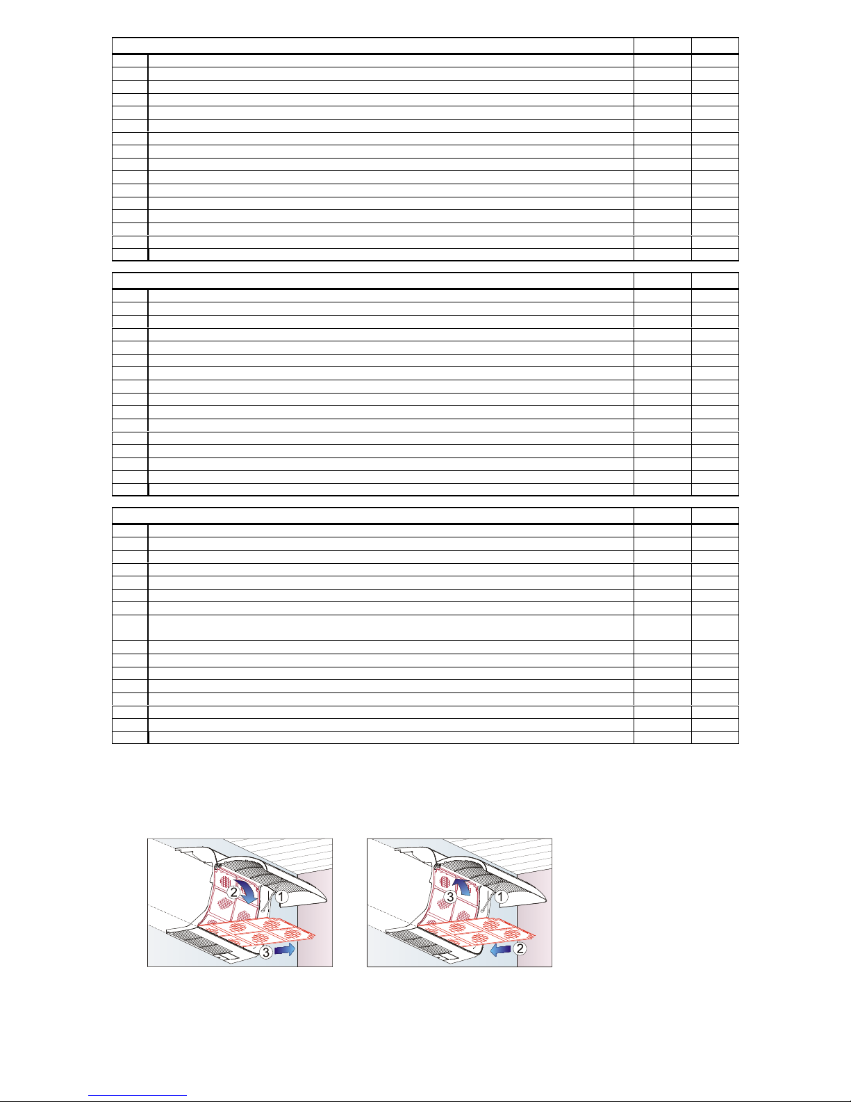
-28-
WM (L) (E) INSTALLATION CHECK LIST
Page
Checked
1
Is the unit square and level with the ceiling? 15
2
Is the correct restrictor(s) fitted ? 16
3
Are refrigerant pipes the correct diameters for the pipe run ? (also see outdoor unit) 16
4
Is the pipework correctly supported throughout its length ? 16
5
Is the expansion and suction pipework insulated right up to the unit ? 16
6
Have all pipework joints been carefully checked for leaks ? -
7
Is the refrigerant charge / oil addition correct ? 27
8
If applicable, has the blue wire on HPC 55000487 been returned to terminal 4 ? 26
9
If the outdoor unit is a DCUE has link JP6 been removed ? 26
10
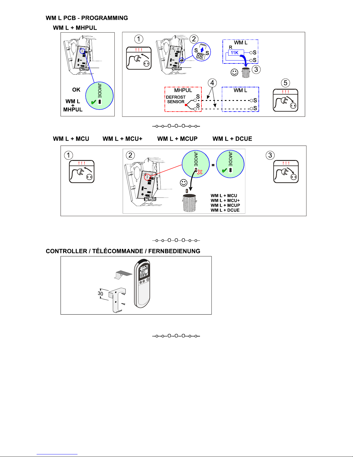
WM L: if the outdoor unit is an MCU, MCU+ or DCUE, has link JMODE been removed (WM L pcb)? 23
11
Is the fuse size correct ? 13
12
Is the interconnecting wiring correct ? 38-40
13
Does the system respond correctly to commands from the controller ? 48-53
14
Is the condensate drain correctly sized, connected, supported and insulated ? 17
15
Has the effectiveness of condensate removal system been tested and there are no leaks ? -
16
Is the air distribution as required? -
CHECK LIST DE L’INSTALLATION DE WM (L) (E) Page Vérifié
1
L’unité est-elle fixée de niveau ? 15
2
Avez-vous monté les bons numéros de buse pour le système ? 16
3
Avez-vous passé les bons diamètres de tuyauteries ? 16
4
Les tuyauteries sont-elles correctement fixées ? 16
5
Avez-vous isolé les tuyauteries jusqu’au chássis de l’unité ? 16
6
Avez-vous effectué une recherche de fuites ? -
7
La charge de réfrigérant et d’huile est-elle correcte ? 27
8
Si approprié, le fil bleu doit revenir a la borne 4 sur la carte HPC 55000487 ? 26
9
Si l’unité extérieure est un DCUE, avez-vous retiré le schunt JP6 ? 26
10
WM L: si l’unité extérieure est un MCU, MCU+ ou DCUE, avez-vous retiré le schunt JMODE (WM L pcb)? 23
11
La taille du disjoncteur est-elle correcte ? 13
12
Les câblages d’interconnexions sont-ills corrects ? 38-40
13
Le système répond-t-il correctement à la télécommande ? 48-53
14
L’evacuation des condensats est-ell correctement raccordée, supportée et isolée ? 17
15
Avez-vous vérifié le bon fonctionnement de l’évacuation des condensats et qu’il n’y a pas de fuites ? -
16
La distribution d’air est-elle correcte ? -
WM (L) (E) MONTAGE PRÜFLISTE Seite Geprüft
1
Ist das Gerät waagerrecht und eben eingebaut ? 15
2
Ist die richtige Düse für das System eingebaut ? 16
3
Sind die richtigen Rohrleitungsgrößen verlegt worden ? (siehe auch Aussengerät) 16
4
Sind alle Rohrleitungen über deren gesamte Länge richtig befestigt ? 16
5
Sind beide Leitungen bis zum Gerätegehäuse isoliert worden ? 16
6
Sind alle Rohrleitungen und Verbindungen auf Leckagen untersucht worden ? -
7
Ist die Kältemittel und Ölfüllung richtig ? 27
8
Falls das Aussengerät der Typ MCUP ist, ist der blaue Draht zurück an Klemme 4
angeschlossen worden ?
26
9
Falls das Aussengerät ein DCUE ist, ist die Brücke JP6 entfernt worden ? 26
10
WM L pcb: Falls das Aussengerät ein MCUP oder MHPUL ist, sind die Brücke JMODE entfernt worden? 23
11
Ist die Sicherungsgröße richtig ? 13
12
Ist die Verbindungsverdrahtung richtig ? 38-40
13
Nimmt das System die Befehle des Reglers an ? 48-53
14
Ist die Tauwasserleitung richtig angeschlossen, aufgehängt und isoliert ? 17
15
Prüfen Sie nach, ob daß Kondenswasser richtig abfliessen kann und keine -
16
Ist die Luftverteilung wie gewünscht ? -
WM (L) (E) USER MAINTENANCE
ISOLATE THE UNIT ELECTRICALLY BEFORE COMMENCING ANY MAINTENANCE WORK
In order to maintain maximum efficiency of this unit, it is important that the filters behind the return air grilles are cleaned regularly.
To remove filters: To replace filters:
Clean the filters by washing in tepid
water, vacuuming or by tapping gently
outside the building.
The unit should always be used with a filter.
Failure to do so will cause a decline in unit performance and may result in malfunction
We recommend that, in order to prolong the life and maintain performance of WM (L) (E) units, they are regularly serviced by an Marstair
Ltd installer/dealer.
Page 29
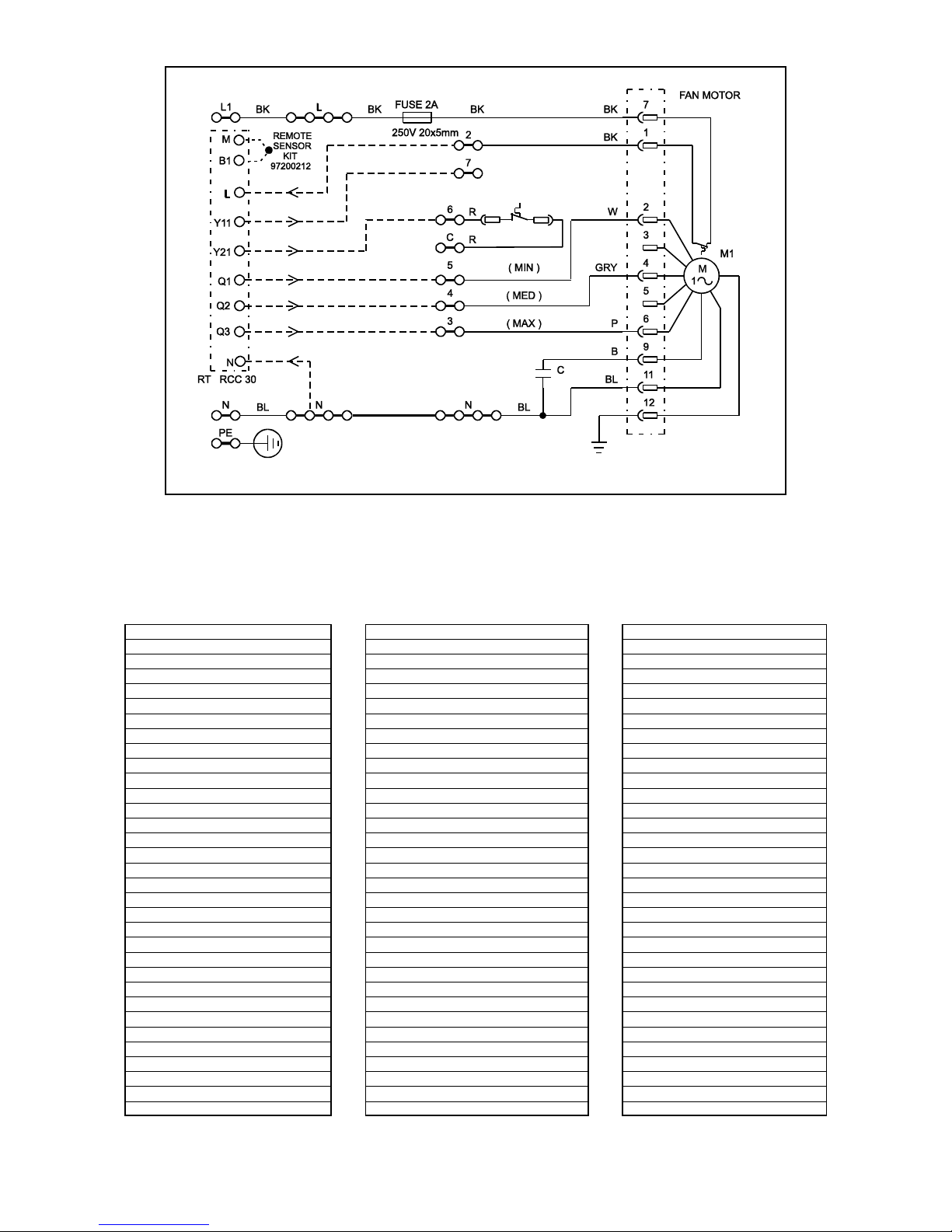
-29-
WM WIRING DIAGRAM
(see page 31 for accessories)
B BROWN B MARRON B BRAUN
BK BLACK BK NOIR BK SCHWARZ
BL BLUE BL BLEU BL BLAU
G GREEN G VERT G GRUN
GRY GREY GRY GRIS GRY GRAU
O ORANGE O ORANGE O ORANGE
P PINK P ROSE P ROSA
R RED R ROUGE R ROT
T TURQUOISE T TURQUOISE T TUERKIS
V VIOLET V VIOLET V VIOLET
W WHITE W BLANC W WEIS
Y YELLOW Y JAUNE Y GELB
AC AIR CONDITIONER AC CLIMATISEUR AC KLIMA ANLAGE
C CAPACITOR C CAPACITÉ C KONDENSATOR
CC CONTROL CIRCUIT CC CIRCUIT DE COMMANDE CC REGEL KREIS
EH ELECTRIC HEATER EH CHAUFAGE ELECTRIQUE EH ELEKTROHEIZUNG
-->-- INSTALLER SUPPLIED -->-- NON FOURNI -->-- BAUSEITS
IRHW INFRA RED (WIRED) IRHW INFRAROUGE (CABLE) IRHW INFRAROT (VEHRDRAHET)
REC INFRA RED (RECEIVER) REC INFRAROUGE (RECEVEUR) REC INFRAROT (EMPFANGER)
F FUSE F FUSIBLE F SICHERUNG
H HEAT/HEATER H CHAUD / CHAUFFAGE H HEIZUNG
HP HEAT PUMP HP POMPE A CHALEUR HP WARMEPUMPENAVLAGE
JP JUMPER / PLUG JP PLUG JP KURTZSCHLUßBRÜCKE
L LIVE L PHASE L PHASE
M1 FAN MOTOR M1 MOTEUR DE VENTILATEUR M1 LUFTER MOTOR
M2 PUMP M2 POMPE M2 PUMPEN
N NEUTRAL N NEUTRE N NEUTRALLEITER
PCB1 CONDENSATE CONTROL PCB1 COMMANDE DES CONDENSATS PCB1 KONDENSAT PUMPREGLER
PE PROTECTIVE EARTH PE MISE À LA TERRE PE SCHUTZLEITER
RL RELAY RL RELAIS RL RELAIS
RT REMOTE THERMOSTAT RT THERMOSTAT A DISTANCE RT FERNBEDIENUNG
RV REVERSING VALVE RV VANNE DE REVERSION RV UMKEHRVENTL
S1 CONDENSATE SENSOR S1 SONDE DES CONDENSATS S1 KONDENSATFÜHLER
Page 30
-30-
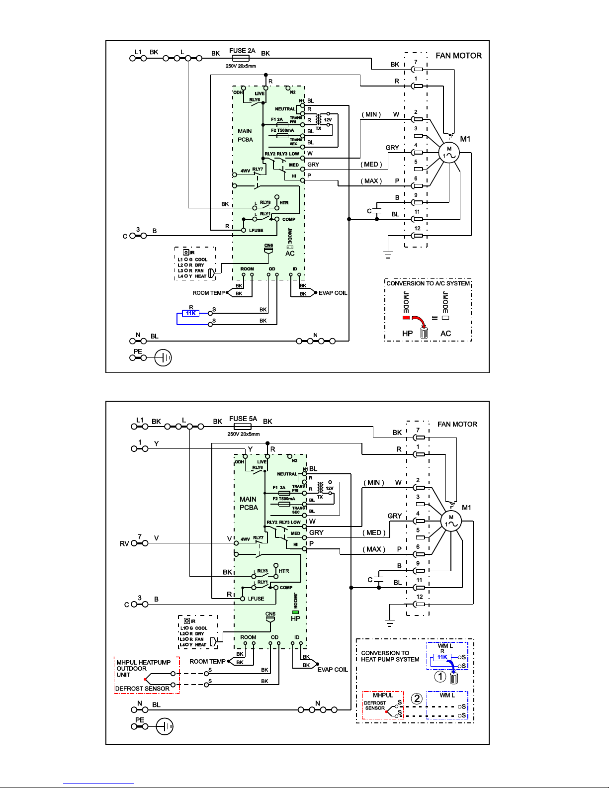
WM L AIR CONDITIONER WIRING DIAGRAM
WM L HEAT PUMP WIRING DIAGRAM
Page 31
-31-
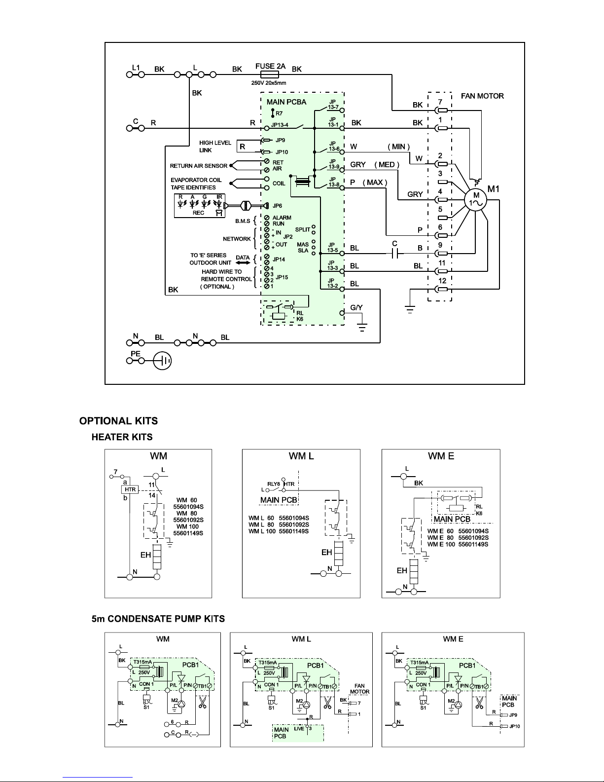
WM E WIRING DIAGRAM
Page 32
-32-
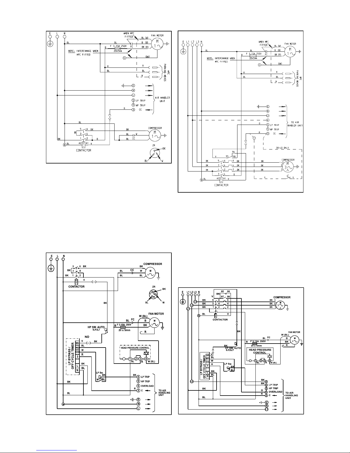
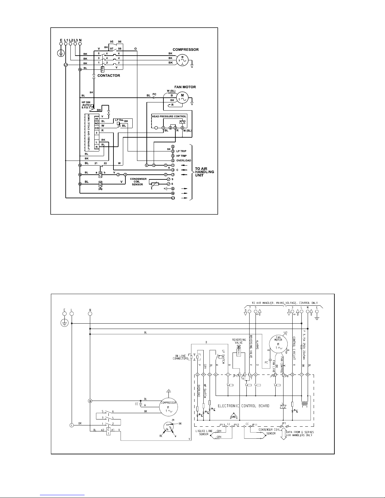
MCU WIRING DIAGRAMS
1 Phase MCU 50-90 3 Phase MCU 50-100
MCU(+) WIRING DIAGRAMS
1 Phase MCU+ 50-90 3 Phase MCU+ 50-100
Page 33
-33-
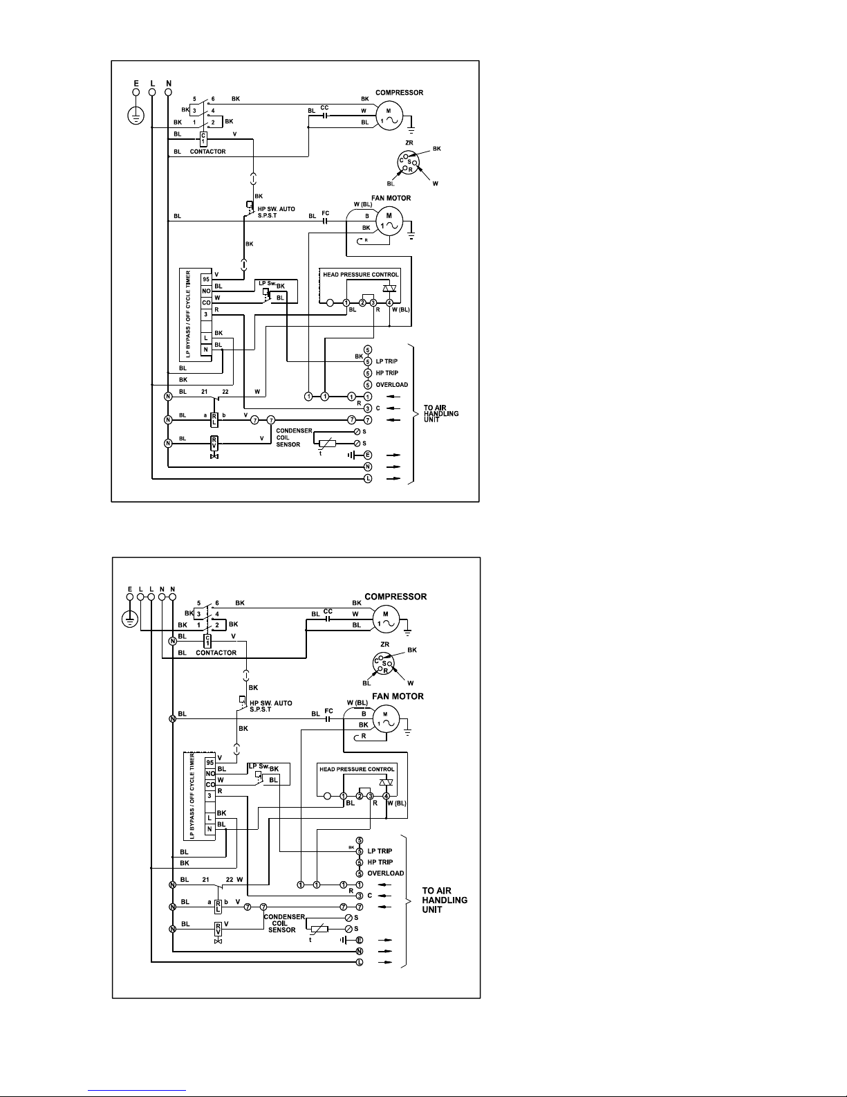
MHPUL WIRING DIAGRAMS
1 Phase MHPUL 50
1 Phase MHPUL 80-90
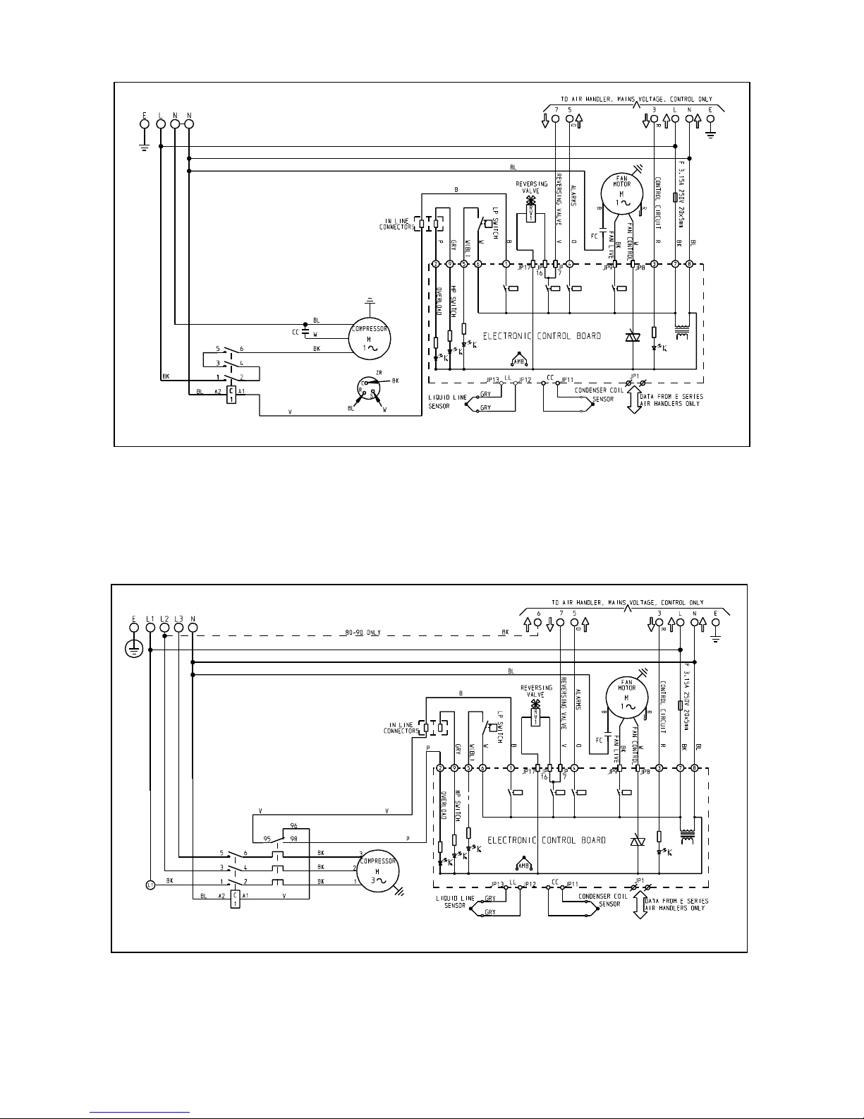
Page 34
-34-
3 Phase MHPUL 50- 90
MHPUE WIRING DIAGRAMS
1 Phase MHPUE 50
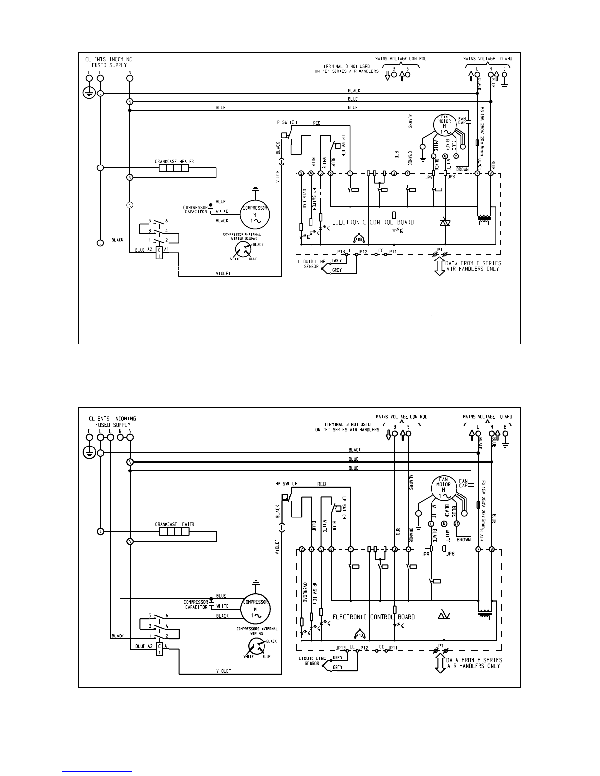
Page 35
-35-
1 Phase MHPUE 80-90
3 Phase MHPUE 50-80
Page 36
-36-
ELECTRONIC DCUE WIRING DIAGRAMS
1 Phase DCUE 50 - 60
1 Phase DCUE 80
Page 37
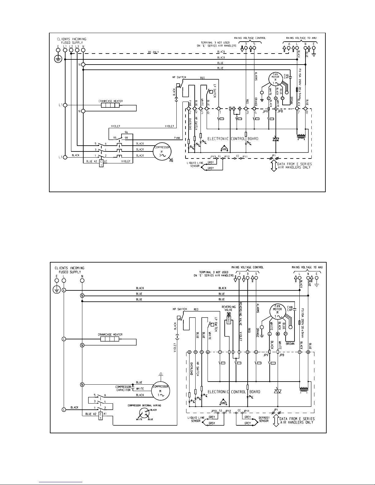
-37-
3 Phase DCUE 50- 80
ELECTRONIC DHPUE WIRING DIAGRAMS
1 Phase DHPUE 50
Page 38
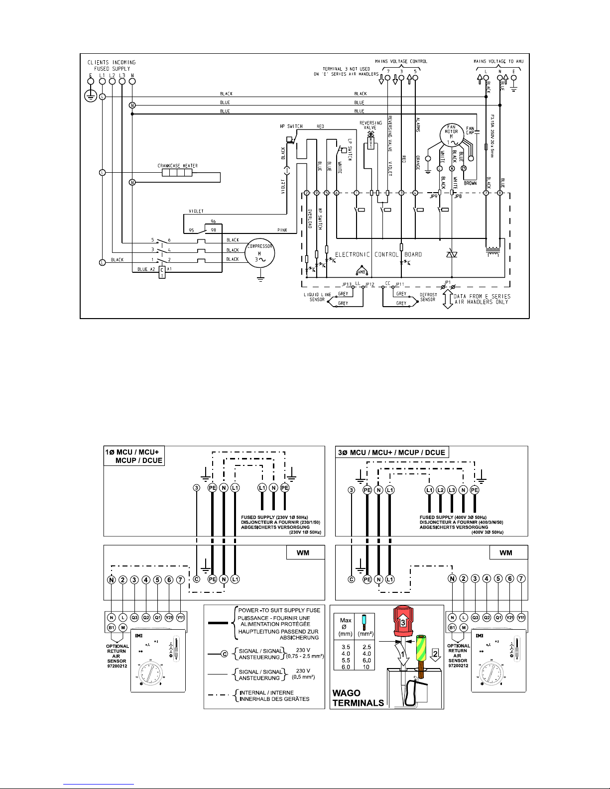
-38-
3 Phase DHPUE 50
INTERCONNECTING WIRING / INTERCONNEXIONS /VERBINDUNGSVERDRAHTUNG
WM
Page 39
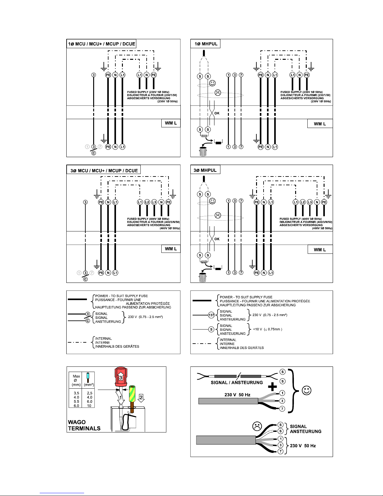
-39-
INTERCONNECTING WIRING / INTERCONNEXIONS /VERBINDUNGSVERDRAHTUNG
WM L
Page 40
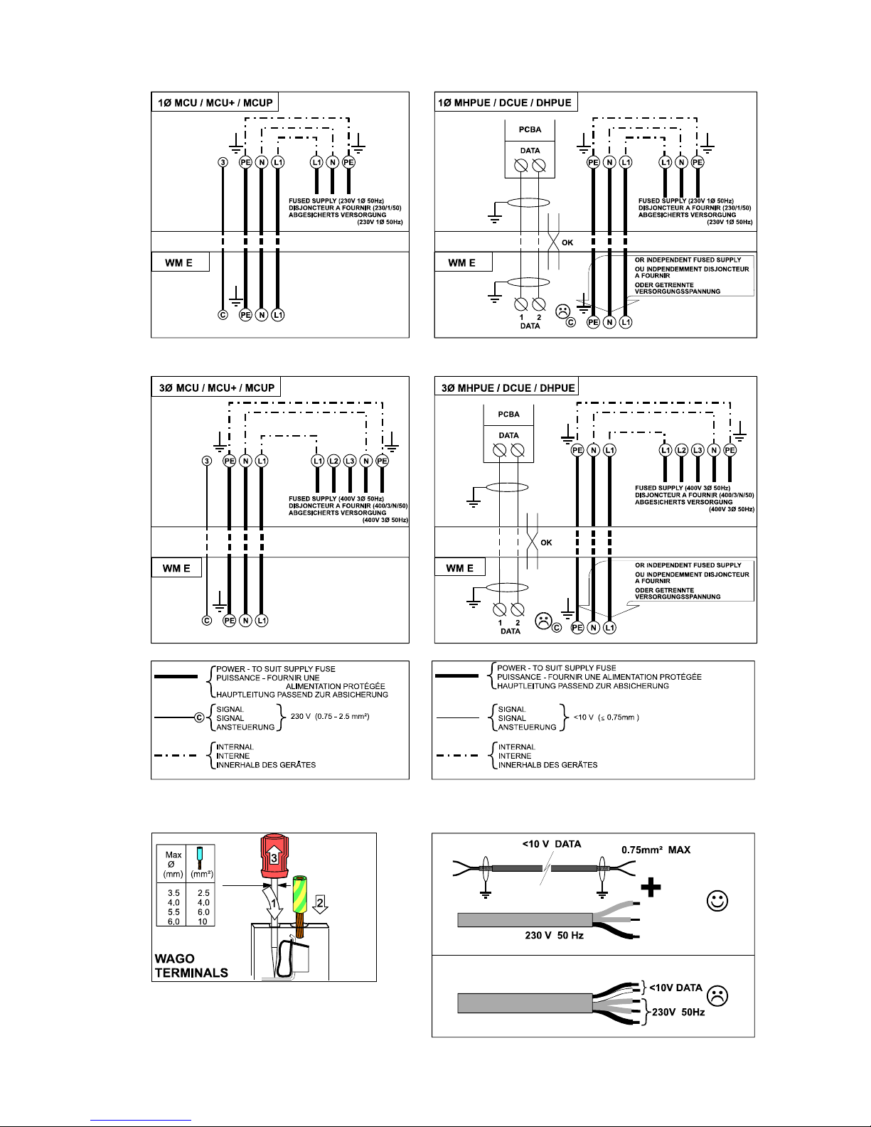
-40-
INTERCONNECTING WIRING / INTERCONNEXIONS /VERBINDUNGSVERDRAHTUNG
WM E
Page 41
-41-
If, as a result of fitting this kit, more than one supply is taken into a unit, that unit must be marked:-
"Two, (or more if applicable), supplies are taken into this equipment.
Isolate both, (all), before undertaking any maintenance work."
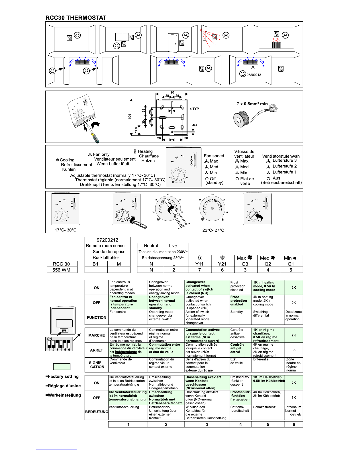
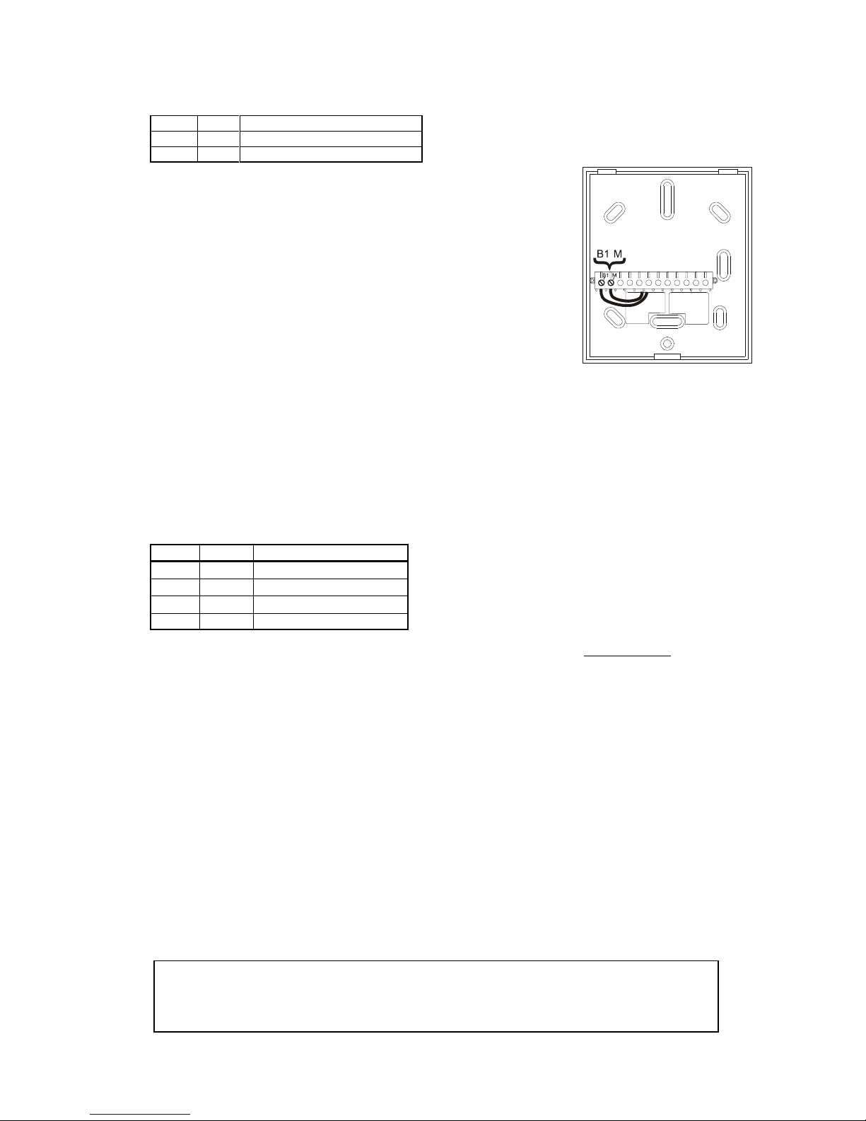
RETURN AIR SENSOR 97200212 (FOR RCC 30 REMOTE CONTROLLER 97200211)
The sensor can be fitted to the return air inlet to an air conditioning unit to improve operation eg. if the wall thermostat
is placed outside the space being conditioned, or if there is considerable stratification in a room with a high ceiling,
where the wall thermostat would not measure a representative temperature.
ITEM QTY DESCRIPTION
1 1 Sensor (2.4m lead)
2 2 Tie wrap
ISOLATE THE SYSTEM ELECTRICALLY PRIOR TO INSTALLATION OF THE
SENSOR
1. Cut off the faston terminals on the cables and strip back.
2. Connect the sensor to terminals B1 and M , as shown (polarity is unimportant).
Changeover to the remote sensor is automatic on power up of the controller.
3. Tie wrap the sensor to a suitable place in the return airflow, where it will soak in
a representative temperature.
4. After installation, adjust the thermostat to confirm satisfactory operation.
5. Sensor input B1-M carries mains potential.
If the sensor cable needs to be extended, the cables used must be suitable for
mains voltage.
--o--o--O--O--O--o--o--
PROGRAMMABLE TIMER KIT 52500151
This kit can be used to give ON/OFF switching of the mains voltage control circuits of WM units where the total current
does not exceed 3 Amps.
ELECTRIC HEATER CURRENTS CANNOT BE SWITCHED DIRECTLY.
It is not required for WM L units which have built in timers.
ITEM QTY DESCRIPTION
1 1 7 Day Programmable Timer
2 1 In Line Fuse Carrier
3 1 5 Amp Fuse, 1" x 1/4"
4 1 Terminal
PROGRAMMER SPECIFICATION: Selection Switch
Type: Digital electronic 230V, 50Hz "OFF",
Programme: 7 day "TMD " (TIMED)
Setting Resolution: 1 minute "CON " (CONSTANT ON)
Max. Switched Current: 3 A (fan load) "ADV " (ADVANCE)
The timer will accommodate 0.75mm
2
to 2.5mm2 wires.
Three core cable is required between the timer and the air conditioning unit.
The timer motor must be connected to an uninterrupted supply source.
TIMER MOUNTING
1. Carefully unpack and identify the components.
2. If the unit is to be surface wired, remove the appropriate knockouts in the backplate. Screw the backplate to the
wall with No. 8 wood screws through the fixing holes.
3. If the backplate is to be fixed to a BS4662 single gang plaster depth box, use 3.5mm machine screws.
WIRING FOR ON/OFF SWITCHING
4. a) Wire timer terminal 'L' to unit terminal 2.
b) Use the terminal provided to connect terminal 4 to live (terminal L, remote controller RCC 30 [97200211] ).
c) Wire timer terminal 'N' to unit terminal N
5. Discard the in-line fuse carrier.
6. Plug in the unit and secure the screws.
7. Program as described in the separate timer instructions.
--o--o--O--O--O--o--o–
Page 42
-42-
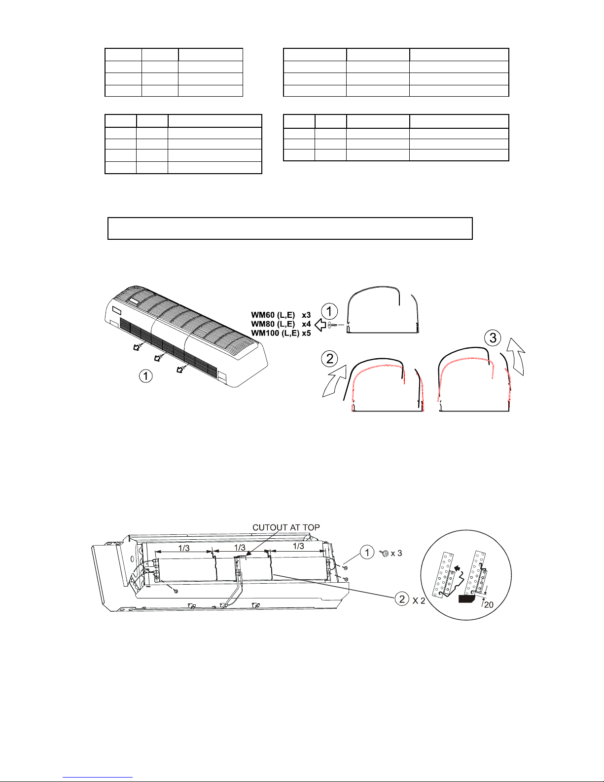
ISOLATE THE SYSTEM PRIOR TO FITTING THE KIT IF THE UNIT HAS BEEN INSTALLED
ELECTRIC HEATER KIT
WM kW Part No. WM L & WM E kW Part No.
60 1.3 55600401 60 1.3 55600411
80 1.8 55600402 80 1.8 55600412
100 2.3 55600403 100 2.3 55600413
ITEM QTY DESCRIPTION ITEM QTY DESCRIPTION SUPPLIED IN KITS
1 1 Coil/element/fuse assy 5 2 Coil clip 55600402/403/412/413
2 3 No.8 screws 6 1 Relay assy 55600401/402/403
3 4 Cable clamps 7 2 No.6 screws 55600401/402/403
4 2 Cable ties
These kits are for use on WM (L) (E) wall mounted units.
It is easier to fit the kit prior to installing the unit.
1. CABINET REMOVAL
2. FITTING THE COIL/ELEMENT/FUSE ASSEMBLY (numbers refer to diagrams)
a) Secure the assembly to the front of the coil, with the thermal cutout at the top (3xNo.8 screws). j
b) Ensure there is a space of 20mm between the top of the drain tray and the bottom of the heater coil.
c) On WM (L) (E) 80 / 100 position the coil clips
k
Page 43
-43-
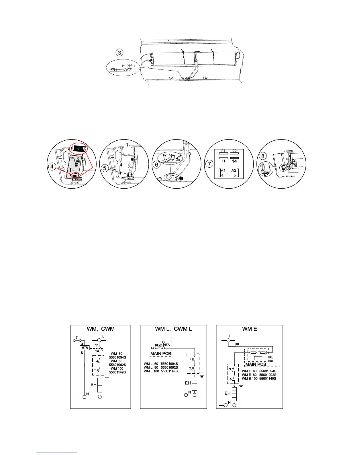
3. WIRING WM L, and WM E
a) Route the harness from the fuse along the back panel using the cable clamps, ensuring the harness is above the
cabinet fixing brackets 3
b) Connect the black wire from the fuse assembly to the PCB relay: 4to ’HTR’ for L models, 5 for E models.
Route the blue wire alongside the existing harness and connect to terminal N on the terminal rail.
Use the cable ties provided to tidy the wires.
c) Connect the earth wire to the nearest cabinet fixing bracket
6.
d) Use the cable ties provided to tidy the wires.
4 WIRING WM
a) Connect a black wire from the fuse assembly to No.14 on the kit relay 7.
b) Fit the relay to the back panel using the 2x No.6 screws 8.
c) Route the harness from the fuse along the back panel using the cable clamps, ensuring the harness is above the
cabinet fixing brackets
3.
d) If there is no free space in the existing “N” neutral terminal, insert the terminal provided and fit the jumper bar
between the existing &”new” terminal.
e) Connect the blue relay wire to terminal N on the terminal rail.
f) Connect the black relay wire to terminal L1 on the terminal rail.
g) Connect the orange relay wire to terminal 7 on the terminal rail.
h) Connect the second black wire from the fuse assembly to the black wire from the element, via the connector.
I) Connect the blue wire from the element to terminal N on the terminal rail.
j) Connect the earth wire clip to the nearest bracket as shown
6.
k) Use the cable ties provided to tidy the wires.
--o--o--O--O--O--o--o–
Page 44
-44-
5m HIGH CONDENSATE PUMP KIT FOR WM UNITS 55600420
ITEM QTY DESCRIPTION
1 1 Pump assembly
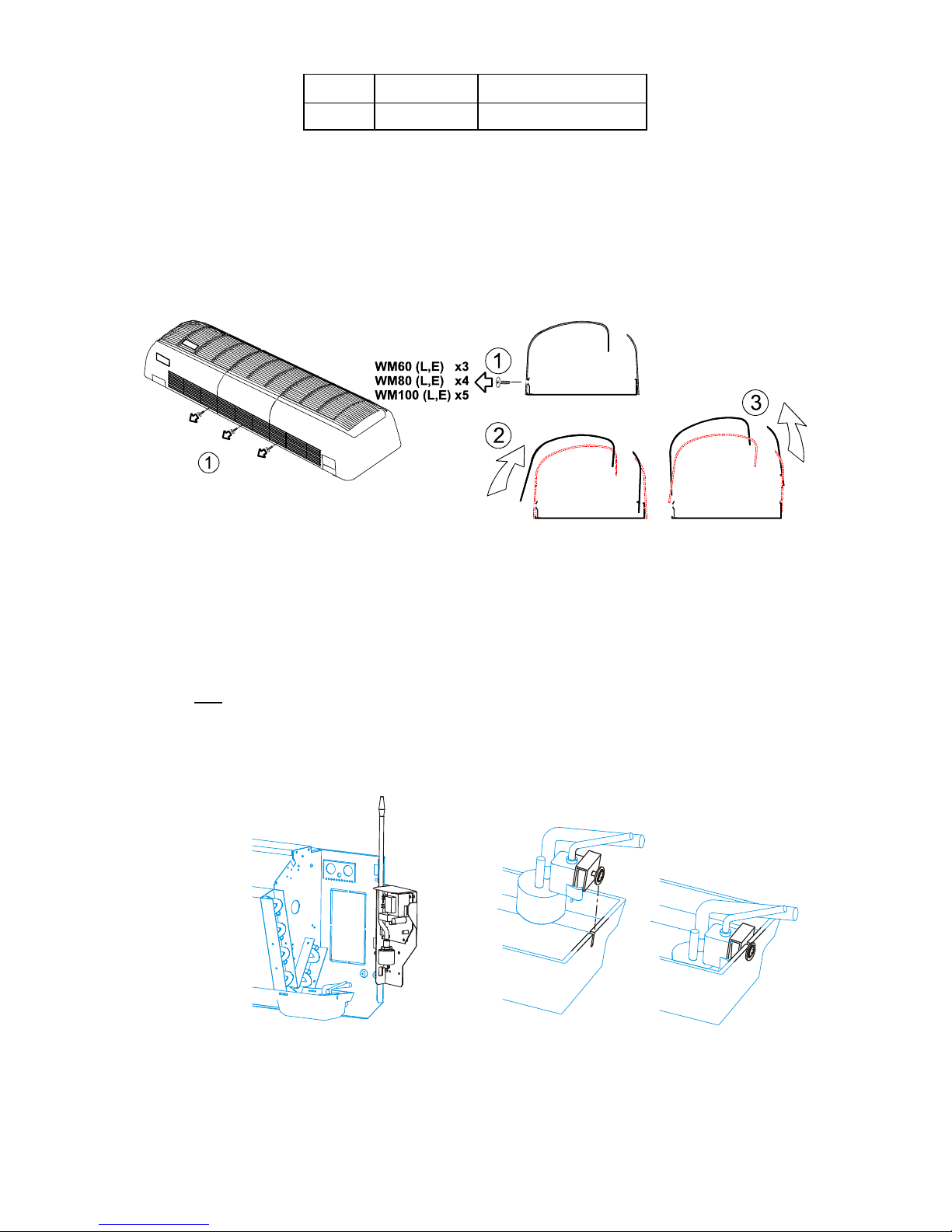
This kit is for use on all versions of WM (L) (E) units and is for condensate removal where a lift of up to 5m is required.
The pump runs on demand.
A high level alarm will switch off the cooling signal until condensate has dropped below a pre-set level.
It is easier to fit this kit before installing the unit.
IF THE UNIT HAS BEEN INSTALLED, ISOLATE THE SYSTEM BEFORE FITTING THE KIT
.
1. CABINET REMOVAL
2. FITTING THE KIT
a) Fit the pump assembly into its temporary position (Fig.1) by sliding the hooks on the pump assembly bracket
into the cut-outs on the back panel side flange.
Note
: This is not the final position, but it makes installation easy.
b) Fit the sensor/filter inside the drain tray (Fig.2). Do not over tighten the screw.
Fig.1 Fig.2
Page 45

-45-
3. WIRING
a) Locate the black, blue and red wires in the unit near the pump and remove the cover from
the black and blue wires.
b) Connect: (i) Black wire to terminal L on the pcb
(ii) Blue wire to terminal N on the pcb
The plastic cover over the pcb can be removed for convenience: retain the cable tie.
c) Cut the centre loop of the red wire and strip back both ends by 5mm. Connect the bared
ends to the black de-mountable plug TB1 (non-polarized) on the pcb.
d) Fit the spare earth wire (clip fitted) to the back panel side flange.
If the plastic cover was removed, secure in its original position with the original cable tie.
Unhook the pump assembly and fit in its final position (Fig. 3).
Connect a drain hose to the white connector when installed.
4. TESTING THE PUMP AND CONTROL
a) Connect a suitably fused supply to the unit (refer to the unit installation instructions). Allow approximately one
minute for the controls and sensor to stabilize.
b) Slowly add water to the condensate tray sump until the pump runs. Initially the pump will be noisy until the air in
the hose has been expelled. It is possible that, on this first cycle, the pump will run dry for a short period (indicated
by noise).
c) Add more water to the sump and the pump will cycle in the normal manner.
d) With the system in cooling mode, continue adding water to the sump until it reaches the higher of the sensor
probes. The cooling cycle will shut down, and the pump will continue to run until the water has dropped below the
level of this probe.
e) Replace the cabinet.
Note: Whenever the electrical supply to a unit fitted with a condensate pump and controls is interrupted, a delay
of up to 1 minute will occur before the compressor or the pump will start when the supply is reinstated.
5. TROUBLE SHOOTING
Unit will not cool No mains supply to the control board
Pump does not run Fuse on control board blown (T315mA x 20mm)
Sensor disconnected from control board
Cooling is interrupted Restriction in pump flow allowing level to rise and trip overflow circuit
Check for blockage or kink in hoses
Condensate at high level - tripping overflow circuit
Filter blocked - Remove and clean
Excessive pump noise Air leak in hoses and/or joints
Pumping without water in sump - control board fault
Loose connection between sensor and control board
Loose fuse, intermittent mains supply to control board
Water syphoning due to lack of air break
6. APPLICATION NOTES
1. The pump will work against a 5m head. Flow rate is highest with minimum head.
2. Long lengths of drain pipe should not be exposed to the outdoor ambient, otherwise freezing of condensate may
occur during winter operation.
3. It is not advisable to have the outlet of the drain well below the position of the pump, otherwise a syphon effect
may open the pump valves and cause noise by admitting air.
4. For normal applications, i.e. where the drain is level or above the pump or within 3 feet below it, no extra check
valves are needed; the pump has its own internal check valves.
5. Ensure that no hose is kinked, as this could seriously affect the pump performance.
6. Clean the filter at regular intervals.
--o--o--O--O--O--o--o–
Fig.3
Page 46
-46-
EMC TERMINATION KIT 55200301
This termination gland is required on all WM E units wherever low voltage signal cables are used (see table below), to
maintain compliance with the EMC Directive. One termination gland can be used for up to 3 cables.
CONTENTS
ITEM QTY DESCRIPTION Type of connection No. of cables required
One termination gland
can be used for up to 3
cables. Each cable is
four core screened
cable, available from
Marstair in 100m rolls,
part number 00526077.
1 1 Gland assembly Wall mounted handset 1
2 1 Screening sock Remote temp. sensor 1
3 2 Cable tie Data to MHPUE/DHPUE 1
BMS control (with alarm) 1 (2)
Networking 2
ISOLATE THE SYSTEM ELECTRICALLY PRIOR TO INSTALLATION OF THIS KIT
Method of installation for individual screened or collectively taped screened cable:
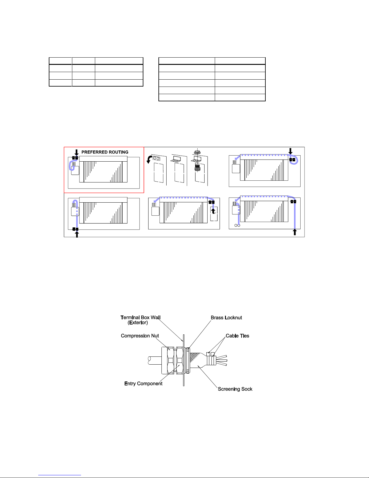
1. The cable routing inside the unit should be chosen to minimise both the route length and the stripped length in order
to minimise the risk of interference. Cable routes and gland brackets are shown below:-
2. Prepare the cable(s) by stripping back the outer sheath and the screenings to expose the cores to a length suitable
for the chosen route to the terminals..
3. Further strip back the outer sheath(s) to expose the individual or collective screening to a length of 25mm. Remove
the first (blue) layer and wrap the now exposed earth wire around the shiny foil layer.
4. Position the assembled termination with the seal in its relaxed state onto the cable(s) such that the end of the thread
is in line with the outer sheath.
5. Tighten the compression nut onto the entry component to effect the IP66 neoprene seal. Remove the brass locknut.
Cut the screening sock in half and fit half of the screening sock over and around the individual/collective core screens
such that the end of the sock is in line with the end of the screening. Tie in position with the cable ties to effect a joint.
6. Thread the individual wires and screening sock through the hole in the gland plate and fit the locknut over the sock.
7. Fit the lock nut over the sock and slightly screw on to the thread.
8. Ensure that the cables can reach their terminals: tighten the lock nut such that the screening sock is secured and
anchored and is in direct contact with the internal wall of the gland plate.
9. Bend the sock such that it cannot short circuit to any electrical connection .
--o--o--O--O--O--o--o–
Page 47
-47-
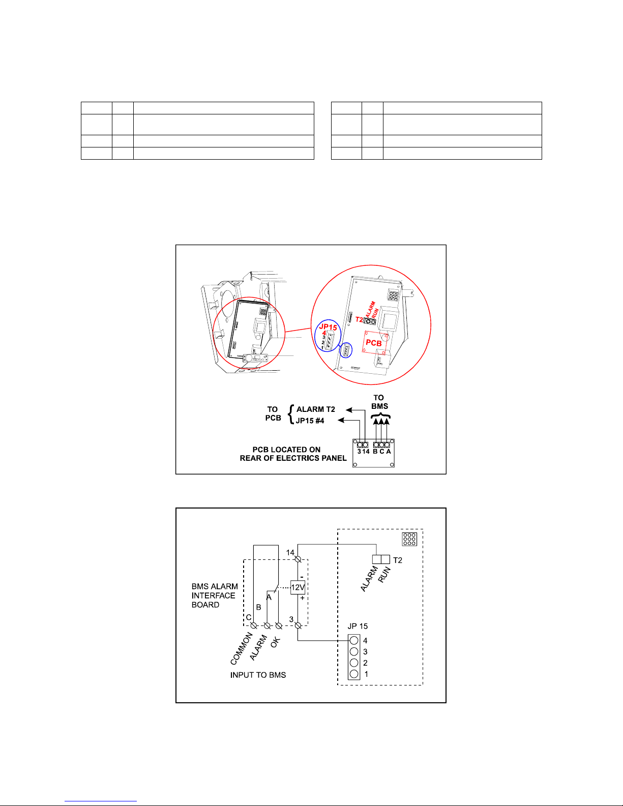
BMS ALARM INTERFACE KIT 53800423 (for WM E)
By fitting a BMS alarm interface kit, a simple common alarm signal is available for volt free input to a BMS network.
Power failure, or any other notifiable alarm state, causes the output relay to de-energise.
Condition OK = system running without fault
Condition Alarm = system mains power loss or notifiable alarm state.
ITEM No DESCRIPTION ITEM No DESCRIPTION
1 1 BMS alarm interface board 4 4 Mounting foot (long: 4 for 600 E, 3 for *75E)
2 4 Mounting foot (self adhesive for IMPACT-E) 5 1 Orange wire
3 4 Mounting foot (hook type for IMAGE-E, WM E) 6 1 Yellow wire
ISOLATE THE SYSTEM ELECTRICALLY BEFORE INSTALLING THIS KIT
MOUNTING
1. After gaining access to the electrics panel, fit the appropriate hook type (4 off) mounting feet to the pcb and mount
on the back of the electrics box.
2. Connect the wires as shown.
--o--o--O--O--O--o--o–
Page 48
-48-
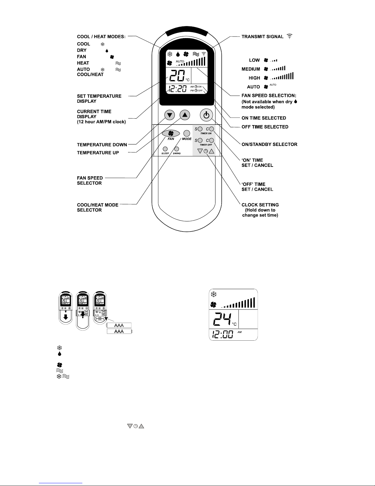
'L' INFRARED REMOTE CONTROL
•
The handset should be pointed towards the unit.
• Two seconds after the last button press, the whole displayed programme is automatically transmitted.
• The unit responds with 1 beep.
• The transmit symbol A flashes whilst transmission is taking place.
• Displayed values may be re-sent at any time by pressing the pink H button twice.
1. Remote Controller Power Up
Slide down the cover and insert The initial display will show:
two "AAA" size 1.5V batteries.
COOL
HIGH FAN SPEED
TEMPERATURE
'ON' TIMER SWITCHED OFF
TIME 'OFF' TIMER SWITCHED OFF
2. Setting Cool/Heat/Dry Modes
COOL - Unit cools when required but cannot heat
DRY - Unit removes moisture by cycling cooling at low speed,
humidity is reduced, but room temperature is not changed.
FAN ONLY - No cooling or heating - fan only
HEAT - If heating is available, unit heats when required but cannot cool.
AUTO COOL/HEAT - Unit cools or heats when required (if heating is available)
3. Setting the Fan Speeds
Repeated pressing of the 'fan speed selection' button selects low, medium, high and auto speeds. In 'auto' selection, the fan runs at high
speed when there is a difference of more than 2
/C between the room temperature and the set (required) temperature, and low speed
when less than 2
/C.
4. Setting the Temperature
Press the ‘up’ or ‘down’ 'set temperature' button to alter the display between 16
/C and 30/C.
By holding both buttons down, the display is changed between
/C and /F.
5. Setting the Clock (Current time)
The ‘up’ and ‘down’ buttons must be held down for 3 seconds before they operate. Continue to hold the button down for rapid change.
6. Programming the Timer
The 24 hour timer can have one ON command or one OFF command or one ON/OFF cycle in a 24 hour period. Blank ON and OFF timer
windows indicate that the timer is not programmed.
Page 49
-49-
7. Setting the ON Time
Press the TIMER ON set ‘S’ button and step to the required ON time. Hold the button down for repeated stepping. Press the TIMER
ON ‘C’ button to cancel the ON time.
8. Setting the OFF Time
Press the TIMER OFF ‘S’ button and step to the required OFF time. Hold the button down for repeated stepping. Press the TIMER OFF
‘C’ button to cancel the OFF time.
9. Only ON Time Selected
Unit will turn ON at the selected time and stay ON.
10. Only OFF Time Selected
Unit will turn OFF at the selected time and stay OFF.
11. Use of the Pink
H ON/STANDBY button when time programmes are selected
At any time, pressing the Pink button will either start the unit or return it to standby mode. The unit will remain at this
condition unless an appropriate ON or OFF time has been programmed.
12. Cold Start
In Cool or Heat mode, not Auto, after more than 3 days without power, or after 2 hours of non-operation, the set
temperature is automatically raised (in heating mode) or lowered (in cooling mode) by 2°C until this temperature is
reached or the unit has run for 20 minutes after which the unit operates with the displayed temperature. This decreases
the time taken to reach set point.
13.Fan Speed ( heat pump systems only)
In heat pump systems, the indoor fan always starts at low speed in heating mode, and changes to the selected speed when the indoor
coil is warm, returning to low speed when not calling for heating.
14. Off cycle delay
To prevent operational problems, cooling restart is delayed for 3 minutes following power up, or from the time the unit was last cooling
or heating, (if heat pump). Cooling or heating, (if heat pump) will operate for a minimum of 2 - 3 minutes.
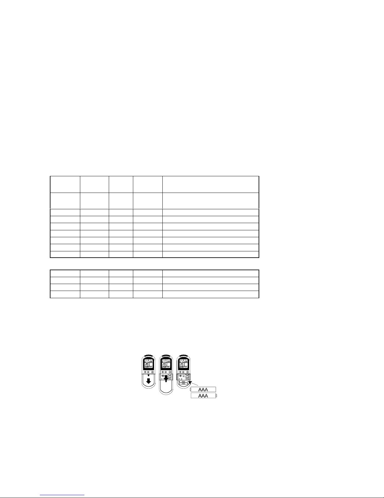
15. Displays
Heat Fan Dry Cool
DIAGNOSTICS
F4ID
Amber Red Red Green
OFF OFF OFF OFF
No power, manual OFF, timed OFF,
condensate high level, fault in condensate
control
OFF
ON
OFF
ON
Cooling mode selected
BLINKS ON
OFF
ON
AUTO - predominantly cooling
ON ON
OFF OFF Heating mode selected
ON ON
OFF
BLINKS
AUTO - predominantly heating
OFF
ON
OFF OFF Fan mode selected
OFF
ON ON
OFF Dry mode selected
BLINKS OFF OFF OFF Outdoor unit defrosting
Diagnostics
OFF
BLINKS x 4
OFF OFF Room sensor missing
OFF
BLINKS x 4
OFF OFF Indoor coil sensor missing
OFF
BLINKS x 4 BLINKS
OFF Heat pump only, outdoor coil sensor missing
OFF
BLINKS x 1
OFF
BLINKS
Compressor overload
16. Heat Pump Only
If the outdoor coil temperature reaches 68°C, the compressor and outdoor fan will stop until the coil cools to 50°C.
17. Commands Refused
a. Attempts to set temperatures outside the display range are not transmitted.
b. If heating commands are refused, the installer's programming is incorrect - call the engineer.
18. Battery Replacement
It is advisable to replace the batteries as soon as the display begins to fade. Correct transmission cannot be guaranteed if the battery
is failing.
2 x 1.5V AAA
batteries
19. Power Cuts
The unit permanently memorises its settings.
20. User Maintenance
Isolate the unit at the mains supply before commencing any maintenance work.
The unit should always be used with a filter. In order to maintain efficiency it is important that the filter behind the air intake grille is
cleaned regularly:
! Remove the filter(s) from behind the air intake grille.
! Wash the filter (in tepid water only) and shake dry before use.
! Alternatively tap the filter gently to remove dust or vacuum clean.
! To clean the unit use soap or a non-scratch liquid cleaner.
–N–N–F–F–F–N–N–
Page 50
-50-
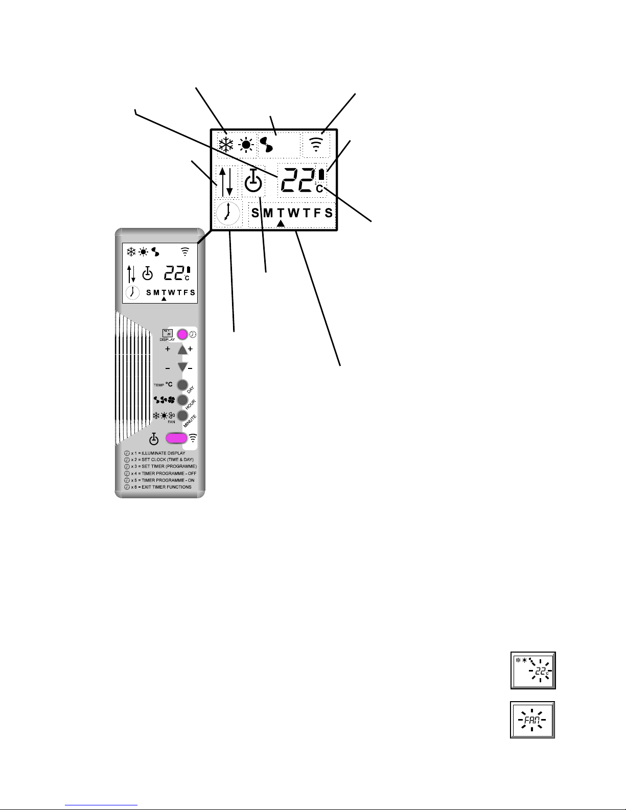
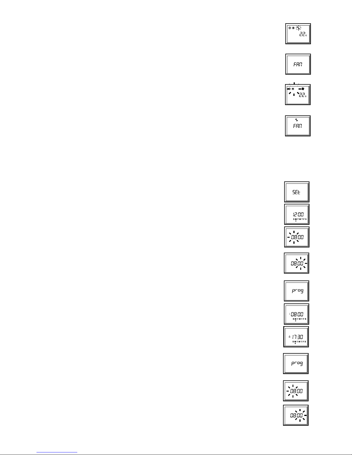
INFRARED ‘E’ REMOTE CONTROLLER OPERATION
Cool/Heat Modes (2.3): Fan Speeds (2.2):
D Cooling only 2 Low fan speed
F Heating only 3 High fan speed
DF Auto cool/heat 4 Boost fan speed A Transmit Signal
FAN Fan only (2.1) 23 Auto High
24Auto Boost
Set Back Battery Indicator
High temp set
B Low battery power (9)
back (7.1)
Low temp set
back (7.2)
Both set back
Set Temp/Functions
22C: Set temperature
18C - 28C (2.1)
SEt: Set day and time (3.1)
Standby
prog: Timer programme (4)
C Standby (1.2) E"": Incorrect input (4)
G On (1.1) 00:00 24 hour clock
(3.1, 4.1, 4.2)
FAN: Fan only (2.1)
--C: Set back function (7)
Timer
¤ Timer set (6.1)
No clock =no timer
programme (6.2)
Days of the week (3.1, 4.1, 4.2)
Sunday to Saturday
•
indicates day chosen
! Press the blue button once to illuminate the display.
! To conserve battery power, the display will turn off after 1 minute if no button is
pressed.
! Point the handset towards the unit when altering settings, unless the handset is wire
connected.
! A single beep means a signal has been accepted.
1 On/standby
1.1 Starting the unit:
Press the blue button once to illuminate the display.
Press the orange button
(C) to switch the unit between 'standby', (red LED on the unit flashing at 5 second intervals), and 'on', (red LED on the unit
permanently on).
1.2 Stopping the unit:
Press the blue button once to illuminate the display.
Press the orange button (
C) to switch the unit between 'on', (red LED on the unit permanently on), and 'standby', (red LED on the unit flashing at 5 second
intervals).
2 Basic Functions
2.1 To change the temperature setting (18C to 28C):
a. Illuminate the display (blue button).
b. Press TEMP C button - the temperature digits will pulse.
c. Press the + or - (• or – ) button, whilst pointing the handset towards the unit, (unless the handset is wire connected). Each
press of the + or - (•/– ) button will increase/decrease the temperature setting by 1C and transmit the new setting to the unit.
A single beep means the signal has been accepted.
NOTES:
z Temperature settings cannot be changed if
FAN is displayed; pressing the TEMP C button in this state will cause the word
FAN to pulse (see 2.3).
Page 51
-51-
2.2 To change the fan speed:
a. Illuminate the display (blue button).
b. Press
234 (fan speed) button - the fan symbol will pulse.
c. Press the + or - (
or ) button to select the 5 fan speeds 2/3/4/23/2 4 (see page 2), whilst pointing the
handset towards the unit, (unless the handset is wire connected). Each press of the + or - (
/ ) button will increase/decrease
the fan speed by 1 step and transmit the new setting to the unit. A single beep means the signal has been accepted.
NOTES:
l In auto high and auto boost modes, the fan runs at low speed unless the room temperature is (2
/ or 3/) different from the set
temperature, in which case the fan runs at high or boost respectively.
l Auto high and auto boost functions cannot be accessed whilst 'FAN ONLY' is selected,
(FAN displayed, see 2.3).
2.3 To change the Cool/Heat/Fan Only Mode:
a. Illuminate the display (blue button).
b. Press
DF6 (Cool/Heat/Fan Only) - the mode symbols will pulse.
c. Press the + or - (
or ) button to select the 4 Cool/Heat modes D/F/DF/FAN (see page 2), whilst pointing the
handset towards the unit, (unless the handset is wire connected). Each press of the + or - (
/ ) button will increase/decrease
the mode by 1 step and transmit the new setting to the unit.
NOTES:
l Transmission of a heat or cool/heat command to a cool only unit will be accepted but the heat function will be ignored - the
unit will continue to operate in cooling only mode.
l Each press of the + (
) button will cycle through the options in the order D/F/DF/FAN, whilst the - ( ) button will
cycle in the reverse order.
l Selecting
FAN (fan only) will display FAN and cause auto high and auto boost functions to default to low speed.
CLOCK/TIMER FUNCTIONS
(If the clock/timer functions are not required, ignore sections 3 to 7.)
l Clock and timer functions are accessed by repeatedly pressing the BLUE clock button (¾).
l The other buttons then assume functions shown in the blue stripe.
3 Clock Functions
3.1 To set the correct day and time:
a. Press the blue button (¾) twice - the display shows SEt.
b. Press the DAY button - the display shows12:00 and the days of the week, with a pulsing arrow () under M (Monday).
c. Press the + or - (
or ) button until the arrow is under the correct day:
d. Press the HOUR button - the hours digits will pulse.
e. Press the + or - (
or ) button until the correct hour is displayed: 24.00 hours is displayed as 00:00.
f. Press the MINUTE button - the minutes digits will pulse.
g. Press the + or - (
or ) button until the correct minutes digits are displayed:
h. Transmit using the orange
A button. A single beep means the signal has been accepted.
NOTES:
l Days, hours and minutes are programmable in any order and may be revisited in any order before transmission.
l Once set, the day or time should only need resetting when the clocks go back or forward; if in any doubt, reset.
4 To view or change the 7 day timer pr ogramme
4.1 To view the programme:
a. Press the blue button (¾) three times - the display shows prog.
b. P ress the DAY button - the screen will display S M T W T F S with an arrow () under M (Monday), the 'on' symbol (G)
and 08:00, (the preprogrammed Monday switch ON time).
c. Pressing the DAY button again will display the 'standby' symbol
(C) and 17:30, (the preprogrammed Monday switch
OFF time).
d. Further pressing of the DAY button will step through first the ON and then the OFF time for each of the 7 days and finally
back to Monday. The whole week's programme may be viewed, without modification, by this means.
NOTES:
l 08:00 and 17:30 are the preprogrammed times; any user changed times will be displayed instead, (see 4.2).
4.2 To change the ON or OFF time of any day or days:
(the timed programme will not operate correctly if the clock in the unit has not been set, see 3.1)
a. Press the blue button
(¾) three times - the display shows prog.
b. Press the DAY button - the screen will display S M T W T F S with an arrow () under M (Monday), the 'on' symbol (G)
and the programmed Monday switch ON time.
c. Repeatedly press the DAY Button until the desired day is indicated by an arrow together with the desired 'on'
(G) or
'standby
'(C) symbol.
d. To change the H our: Press the HOUR button - the hours digits will pulse. Press the + or - (
or ) button until the
desired hour is displayed.
e. To change the Minutes: Press the MINUTE button - the minutes digits will pulse. Press the + or - (
or ) button until
the desired minutes are displayed.
f. Press the DAY button to continue to the next ON or OFF time, and repeat until all required days have been re-programmed,
then transmit using the orange
A button. A single beep means the signal has been accepted.
Page 52
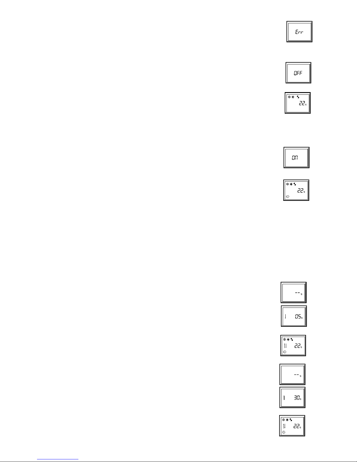
-52-
NOTES:
l If an illogical selection is made (e.g. 'off' time earlier than 'on' time, or 'on' time with no 'off' time, or 'off' time with no 'on'
time), the programme will not move on to another day, or transmit, until the error is removed.
E"" will be displayed each
time the DAY, or orange
A button is pressed, and the display will switch between 'on' and 'off' times until a logical time is
entered.
5 Switching the timer off
5.1 To return a unit, currently running under a timed programme, to MANUAL ON/OFF control:
a. Press the blue (¾) button four times - the display shows OFF.
b. Transmit using the orange A button. A single beep means the signal has been accepted.
c. The screen will display the basic functions. The clock
¾ symbol will be removed to show that the unit has been
instructed to run under manual ON/OFF control.
NOTES:
l If the
OFF display is transmitted during a timed run period, the unit will continue to run until turned off by pressing the
orange
A button, (whilst the basic screen is displayed).
l If the
OFF display is transmitted during a timed off period, the unit will remain in 'standby' until turned on by pressing the
orange
A button, (whilst the basic screen is displayed).
l Any setback functions programmed will also be switched off (see section 7).
l The programme
OFF signal can be re-transmitted at any time.
6 Switching the timer on
6.1 To run a unit under a timed programme:
(the timed programme will not operate correctly if the clock in the unit has not been set, see 3.1)
a. Press the blue button
(¾) five times - the display shows ON
b. Transmit using the orange A button. This will transmit the programme in the handset to the unit.. A single beep means
the signal has been accepted.
c. The screen will display the basic functions and the clock
¾ symbol to show that the unit has been instructed to run
under timed ON/OFF control.
NOTES:
l If the
ON display is transmi tted during a timed run period, the unit will continue to run until turned off by the timer
programme.
l If the
ON display is transmitted during a timed off period, the unit will remain
in clock controlled 'standby' until turned on by the timer programme.
l Any setback functions programmed will also be restored, (see section 7).
l The programme
ON signal can be re-transmitted at any time
7 Set Back Function
During a programmed switch OFF period it is possible to have the unit automatically heat (if electric heating is fitted or it is a heat pump unit) if the
temperature falls below a preset LOW limit, or cool if it rises above a preset HIGH limit.
NOTES:
l If either set back temperature is set to anything other than --°C, the indoor unit's fan will run at low speed during the switched OFF period in order
to circulate air over the sensor.
l The set back function will apply to all 7 days of the week, even if the unit does not normally run, say at weekends.
l Active set back is indicated by a double flash of the red LED on the unit, repeated at 15 second intervals.
7.1 To set or change the Set Back LOW temperature limit:
a. Illuminate the display (blue button).
b. W hilst holding down the MINUTE button, press the Blue
(¾) button, then release both buttons - the screen will
display --°C. (If a set back temperature has already been set, this temperature and a down arrow
9will be displayed).
c. If no temperature has been set, press the + (
) button first, then the + or - ( or ) buttons to select the minimum
temperature to which the room should fall before the unit switches on in heating mode.
(Temperature range from 5°C to 1° below the set point temperature).
d. Transmit using the orange
A button. A single beep means the signal has been accepted.
NOTES:
l The up and down
89 arrows will be added to the basic display, to indicate that set back has been programmed.
l Setting the set back LOW function only will default the setback HIGH function to 30°C
l Pressing the - (
) button at 5°C will display --°C and remove both the LOW and HIGH set back functions.
7.2 To set or change the Set Back HIGH temperature limit:
a. Illuminate the display (blue button).
b. W hilst holding down the HOUR button, press the Blue
(¾) button, then release both buttons - the screen will display
--°C. (If a set back temperature has already been set, this temperature and an up arrow
8 will be displayed).
c. If no temperature has been set, press the - (
) button first, then the + or - ( or ) buttons to select the maximum
temperature to which the room should rise before the unit switches on in cooling mode.
(Temperature range from 30°C to 1° above the set point temperature).
d. Transmit using the orange
A button. A single beep means the signal has been accepted.
NOTES:
l The up and down
89 arrows will be added to the basic display, to indicate that set back has been programmed.
l Setting the set back HIGH function only will default the set back LOW function to 5°C
l Pressing the + (
) button at 30°C will display --°C and remove both the HIGH and LOW set back functions.
Page 53
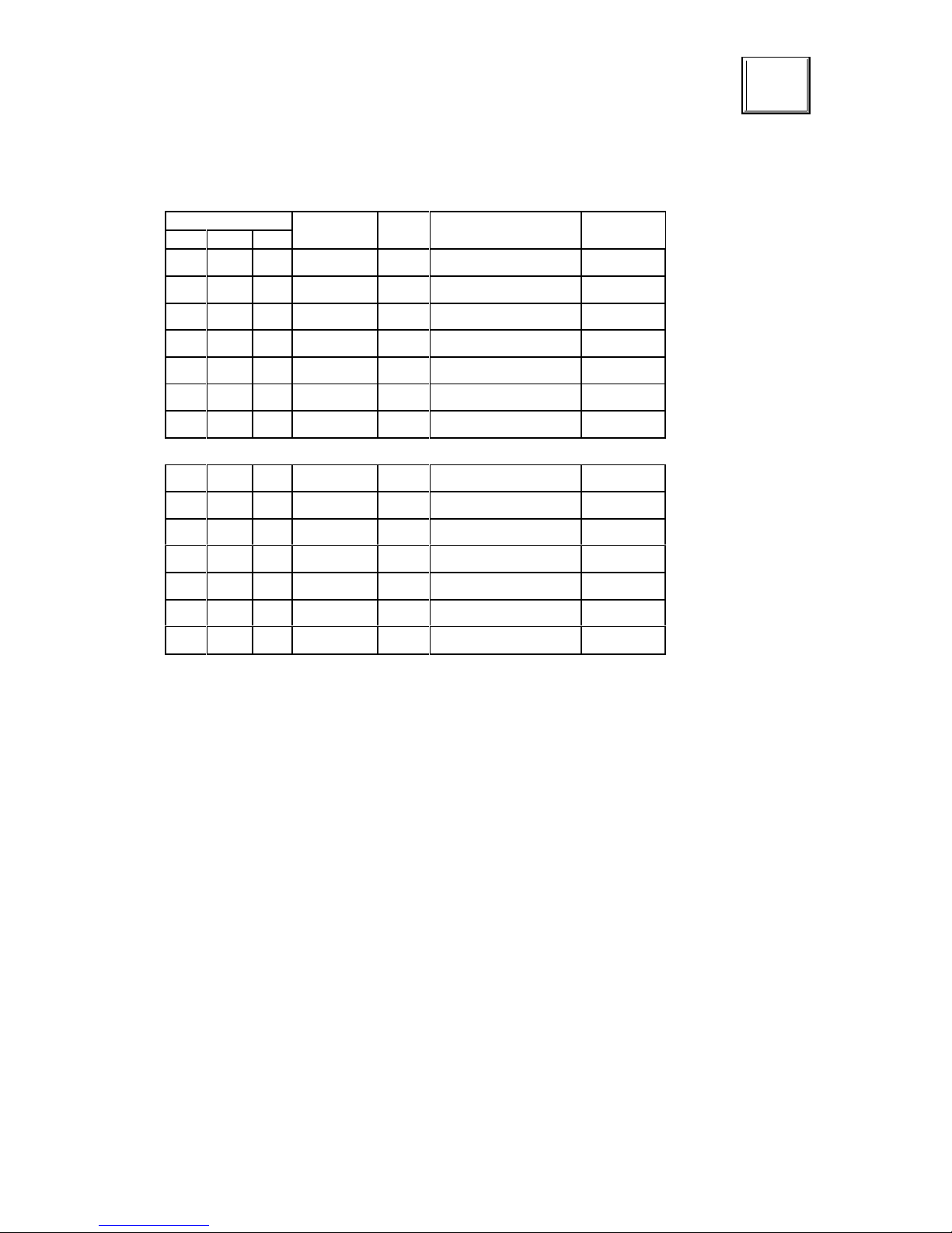
-53-
8. Low battery power warning
Low handset battery power is indicated by the battery symbol B.
B
NOTES:
z When required, replace the battery with an equivalent alkaline type ensuring that the connector is firmly in position.
z Do NOT use a rechargeable battery.
9. LED Status and Alarm Indicators
Electronic indoor units have coloured LED's and a sounder to indicate the following status and alarm functions.
LED Flash Rate
ON/OFF
(seconds)
Sounder Condition Status
Green Amber Red
C
ON OFF In Operation Normal
F
ON OFF Heating Demand Normal
D
ON OFF Cooling Demand Normal
C
0.5 / 5.0 OFF Standby Normal
C
0.5 / 15 OFF Clock Controlled Standby Normal
C
2 x 0.5 / 15 OFF Setback Normal
C
0.5 / 0.5 OFF Filter Clean Advisable
Normal
F
0.5 / 0.5 BEEPS Network Warning Call Engineer
D
0.5 / 0.5 BEEPS High Condensate Level Call Engineer
F C
0.5 / 0.5 BEEPS Low Pressure Warning Call Engineer
D C
0.5 / 0.5 BEEPS High Pressure Warning Call Engineer
D F C
0.5 / 0.5 BEEPS Contactor Overload Operated Call Engineer
D F
0.5 / 0.5 BEEPS Outdoor Fan Fail Call Engineer
D F C
ON BEEPS Sensor Fault Call Engineer
z
To avoid unnecessary annoyance, the sounder will stop after 30 seconds and will sound again for 30 seconds if any signal is transmitted
to the unit, including start up.
z If the sounder beeps in this way call the Engineer.
NOTES:
z During standby the
C LED will flash at 0.5 second intervals as a reminder that the unit has power but is not running.
z To clean the unit use a non-scratch liquid cleaner.
--o--o--O--O--O--o--o–
Page 54
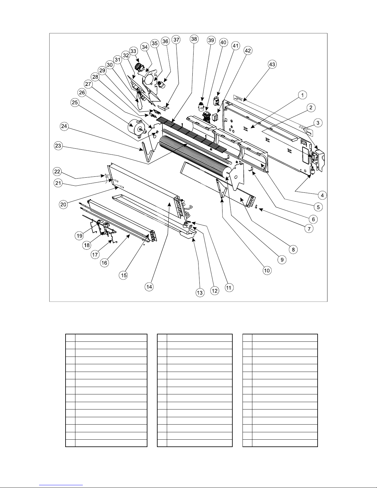
-54-
EXPLODED VIEW OF WM (L) (E) with COM PONENT IDENTIFICATION
1 Back panel 16 Heater elements 31 Main PCB (WM L)
2 Condensate pump PCB 17 Heater coil retaining clip 32 Main PCB (W M E)
3 Condensate pump bracket 18 Heater cutout bracket 33 Terminals (WM L, E)
4 Condensate pump 19 Heater cutout 34 Terminal mounting bracket
5 Scroll 20 Return air sensor (WM L, E) 35 Electrics panel
6 Case fixing bracket 21 Coil sensor (W M E) 36 Capacitor (WM L, E)
7 Drain tray clip 22 Coil sensor (W M L) 37 IR PCB mounting bracket
8 Coil (rear) 23 Air flow cut-off 38 Fan guard
9 Fan 24 L/H coil support bracket 39 Capacitor (WM)
10 R/H coil support bracket 25 Resistor 40 Terminals (W M)
11 Condensate pump sensor/filter 26 Motor 41 De-ice thermostat (W M)
12 Sensor bracket 27 Fan support bracket 42 Heater relay (W M)
13 Drain tray 28 IR receiver PCB (W M E) 43 W all mounting bracket
14 Coil (front) 29 IR receiver PCB (WM L)
15 Heater coil 30 Blanking plate (WM L, E)
Page 55
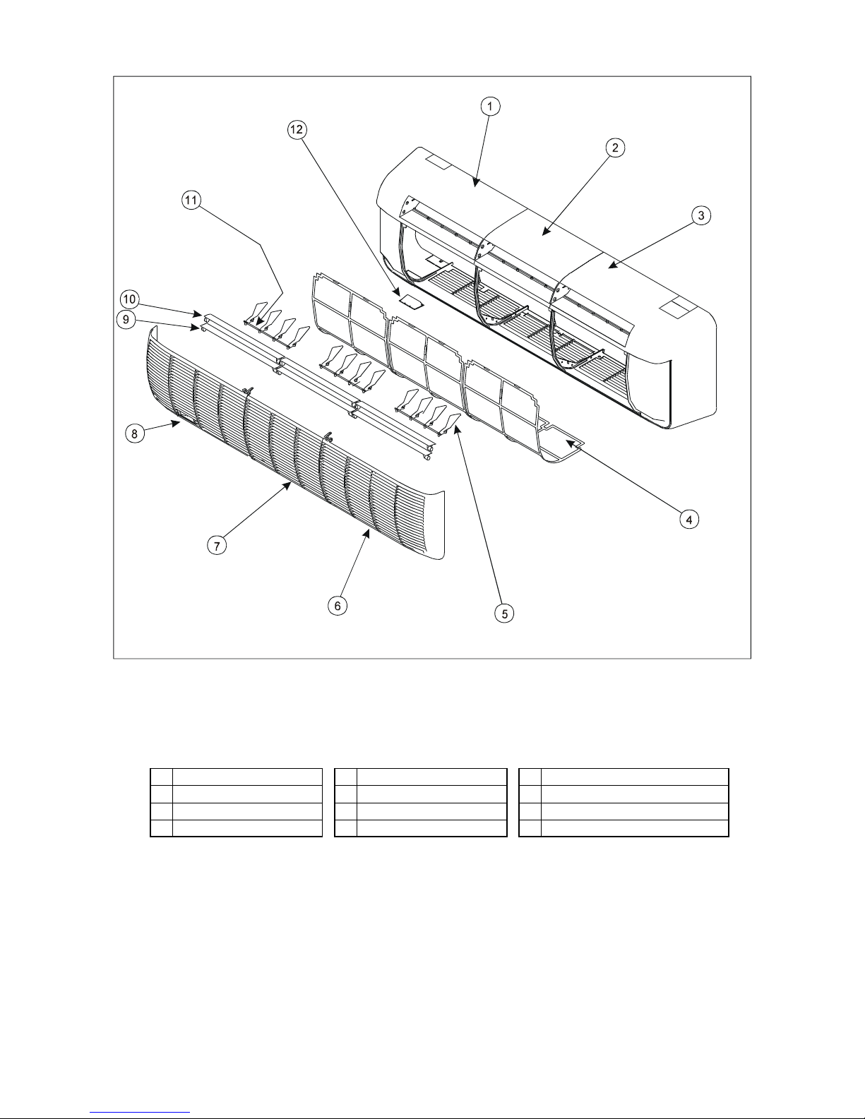
-55-
EXPLODED VIEW OF CASE
1 Cover ( L/H) 5 Vertical air deflection vane 9 Horizontal air deflector vane (lower)
2 Cover (centre) 6 Grille (R/H) 10 Horizontal air deflector vane (upper)
3 Cover (R/H) 7 Grille (centre) 11 Connecting rod
4 Filter 8 Grille (L/H) 12 Blank (WM): IR lens (WM L, WM E)
Page 56
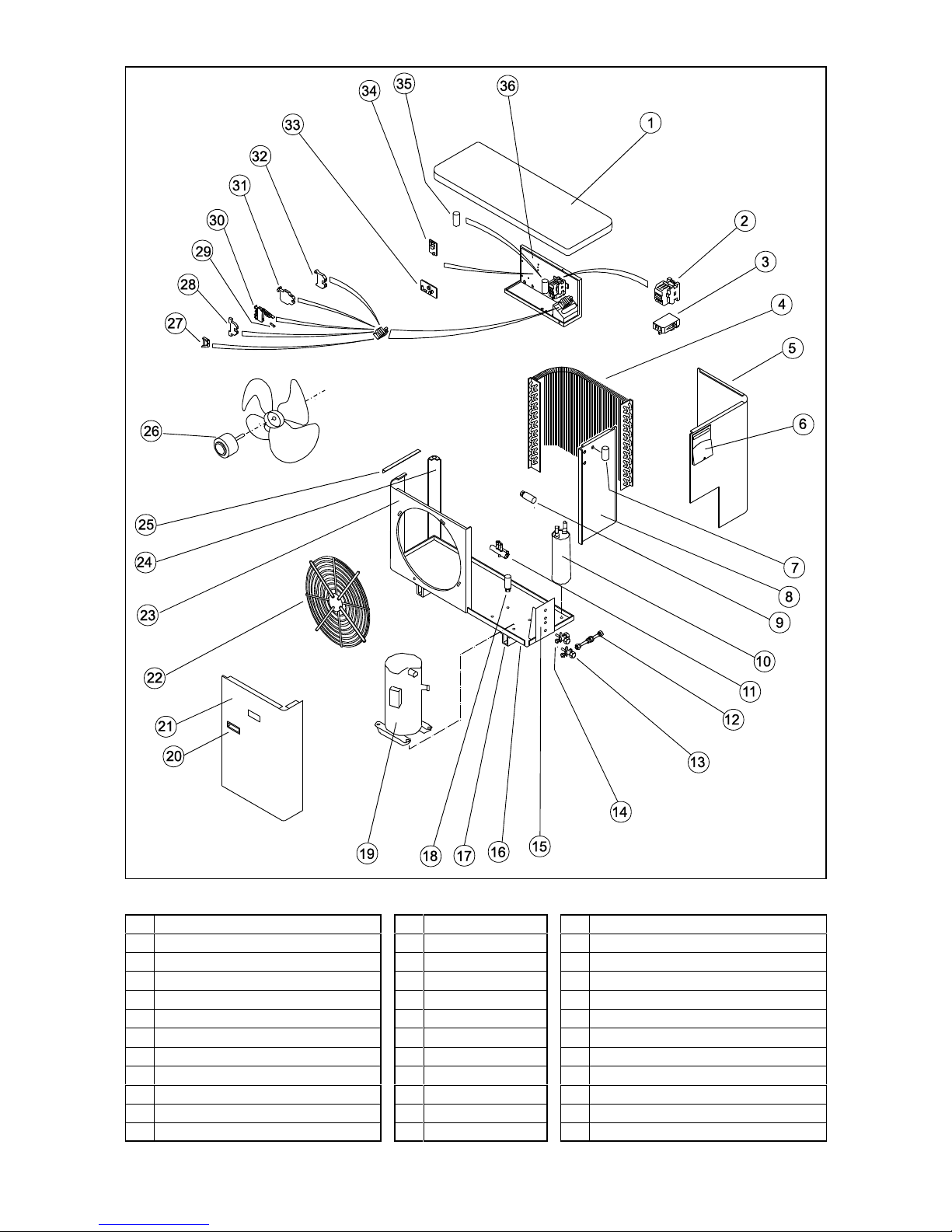
-56-
MCU(+) / MHPUL(E) COMPONENT IDENTIFICATION
1 Lid 13 Service valve (liquid) 25 Support bracket
2 Contactor 14 Service valve (suction) 26 Fan / motor assy
3 Overload 15 Valve panel 27 End clamp
4 Heat exchanger 16 Base 28 Terminal (screw - screw )
5 Rear access panel 17 Mounting foot 29 Fuse
6 Mains terminal cover 18 LP switch 30 Fuse terminal
7 Fan capacitor 19 Compressor 31 Terminal (4 way)
8 Bulkhead panel 20 Handle 32 Earth terminal
9 HP switch (manual, option) 21 Front access panel 33 Head pressure control pcb (MCU+ MHPUL)
10 Suction accumulator (MHPUL, MHPUE) 22 Fan guard 34 3 minute timer pcb (MCU+ MHPUL)
11 Reversing valve (MHPUL, MHPUE) 23 Fascia panel 35 Compressor capacitor
12 Expansion assy (inc. restrictor) 24 Corner panel 36 Electrics box
Page 57
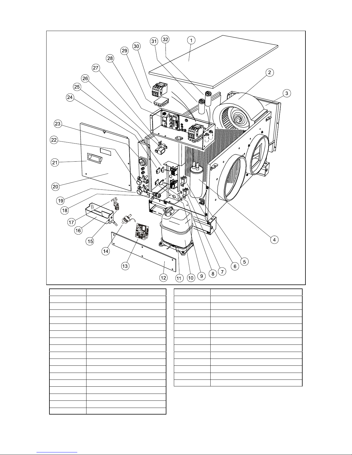
-57-
DCUE / DHPUE COMPONENT IDENTIFICATION
1
Lid
19
Service valve
2
Fan assembly
20
Panel electrics access
3
Panel right hand access
21
Handle
4
Accumulator
22
Service valve
5
Spire c lip
23
Isolator
6
Switch LP auto
24
End clamp
7
Switch HP auto
25
Terminal
8
Terminal 4 way
26
Reversing valve (DHPUE)
9
Terminal fused
27
Solenoid
10
Compressor
28
Power board
11
Crankcase heater
29
Overload (3ph)
12
Cover sump housing
30
Contactor
13
Condensate pump pcb
31
Fan capacitor
14
Condensate pump
32
Compressor capacitor (1ph)
15
Filter
16
Condensate sump
17
Water level sensor
18
Expansion assembly
Page 58
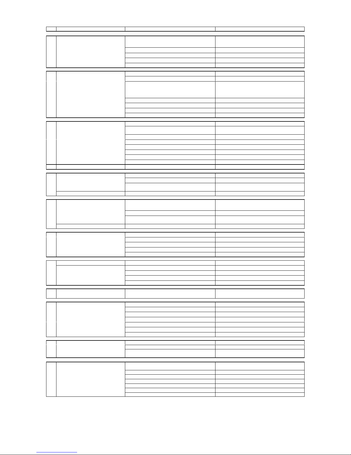
-58-
GENERAL FAULT FINDING (ALL SYSTEMS)
CONDITION POSSIBLE CAUSE ACTION
A Indoor fan motor will not run
No electric supply at socket or switched fuse box
Check fuse rating and replace if necessary. Check for
loose electrical connections
Unit wiring fault Check wiring and connections
Fan motor capacitor defective Replace if faulty
Fan motor defective Replace if faulty
Internal fuse blown Clear fault and replace fuse
B Inadequate cooling or heating
Dirty evaporator fins/filter Clean if blocked
Evaporator motor not running As in section A
Refrigerant shortage or excess
Check for leaks. Repair, evacuate and recharge or
check for high head pressure and recover refrigerant
if necessary
Faulty or incorrectly set thermostat Replace if faulty
Dirty condenser Clean if necessary
Faulty compressor Replace
LP cutout circuit open (if LP fitted) Check as refrigerant shortage or excess
C Compressor and outdoor fan motor
LP cutout circuit open (if LP fitted) Check as above
will not run
No electric supply at socket or switch fuse box
Check fuse rating and replace if necessary. Check for
loose electrical connection.
Unit wiring fault Check wiring and connections
Capacitor, thermostat, relay or overload defective Replace if faulty
Compressor failure Replace if faulty
Controls not set properly Check and rectify
Off cycle delay operating If applicable, wait 3 minutes
High condensate level detected See G
Compressor runs, outdoor fan doesn't Pressure at sensor <200psig Normal: or short of gas
D System runs for long periods and will
Unit underrated for conditioned area Check heat load against capacity
not cycle
Thermostat not operating correctly Check wiring, position of phial and operation
Refrigerant shortage
Check for leaks. Recover, repair, evacuate and
recharge
Indoor coil dry or partly sweating Dirty condenser Clean fins if necessary
E Indoor coil frosting
Refrigerant shortage
Check for leaks. Recover, repair, evacuate and
recharge
Dirty evaporator fins/filter Clean if blocked
Running in cool ambient without a head pressure
controller
Fit head pressure controller
If room temperature is also low Thermostat set too low or cooling permanently Reset or replace
F Noisy unit
Fan fouling cowl (outdoor unit) Realign fan
Worn motor bearing Replace motor
Casing or piping vibration Check cause and rectify
Loose parts or mounting Find and tighten
Bent fan blade Replace fan
G Water leaking from unit
Blocked drain or filter Clear obstruction
Units with lift pump or condensate pump No supply to pump or loose connection Secure the supply
Pumping slowly Check drain pipes; if clear, replace pump
Pump windings shorted Replace pump
Fouled sensor (5m condensate pump only) Clean sensor
H Pump always runs
Faulty sensor or pcb Replace sensor or pcb
I No heating
Controls not set for heating Reset
Unit wiring fault Check wiring and connections
Dirty evaporator fins/filter Clean
Faulty thermostat Check for signal; replace if faulty
Faulty heater element Replace
Faulty heater cutout Replace, (check for short circuiting)
Reversing valve jammed A light tap may free it; preferably replace
J
Overload tripped on three phase
units
High voltage supply Max rated voltage 254v -- check supply
Compressor failure Replace
Fuses blown
Replace fuses and investigate reason for fuses
blowing
K Outdoor unit does not operate
No mains supply
Check fuse rating and replace. Check for loose
electrical connections
Supply below 187V Check supply
Isolator switched off Turn isolator on
Internal fuse blown Check fuse and replace
Data wires disconnected Reconnect data wires
No command signal Check indoor unit
Off cycle delay operating Wait in cooling for 3 minutes
--o--o--O--O--O--o--o--
Page 59
-59-
SPECIFIC FAULT DIAGNOSIS FOR WM L UNITS
CONDITION POSSIBLE CAUSE ACTION
Check for alarms
i LEDs flashing - see table below
ii
If NO external connections are made to alarm terminal 5, the presence of an alarm condition can be tested for by checking for mains
voltage at terminal 5; full mains voltage = Alarm; less than mains voltage = Clear.
The outdoor unit can be caused to operate for test purposes by temporarily linking live directly to terminal 3
(up to 20 seconds delay)
L Outdoor unit runs continually at high Charge link still fitted Remove charge link
speed MHPUL in heating Normal
Minimum speed adjustment set too high Reset minimum speed
If all external devices test O.K. the outdoor unit pcb must be replaced
M No LED's lit or flashing
Unit commanded to be OFF Transmit 'ON'
No mains supply or internal fuse blown. (Fuse
F2 on internal control board blown during
configuring)
Check electrical supply and fuses
Fan motor plug disconnected Reconnect fan motor plug
Motor internal thermal protector operated Check motor and rectify
Cables to fascia not connected Reconnect
Circuit board fault Check circuit board and replace
High water level Check pump circuit (if fitted)
N All LED's lit, one flashing
Temperature sensor problem See table below
Resistor problem (non MHPUL) Check resistor connected
Outdoor sensor problem (MHPUL)
Replace outdoor unit sensor/check
interconnecting wiring
P
Indoor unit continues after stop/off
command
Overrun of 30 seconds in heating Normal
Q
Unit will not respond to infrared
commands.
No audible answer signal
Battery discharged Replace battery
Handset corrupted Reset
R
Unit does not switch on/off at
intended times
Power cut has occurred
Send any command from the handset to
synchronise the timer
S
Unit not running in intended
mode/temperature
Power has been shut off for three or more
days, unit is exercising default programme
Use handset retransmit button
T
Fan does not run at the intended
speed
Heat Pumps Only
Fan runs at low speed until indoor coil is
warm, then changes to intended speed
U Short cycles between cool and heat System oversized for room Use cool or heat programmes NOT 'Auto'
V
First operation, room is overcooled
or overheated by 2
/C
Set point temperature reverts to normal after
deadband is reached or 20 minutes of
operation
Normal
W Handset will not transmit
Heating commands Incorrectly configured - see page 23
Any commands Battery flat
X Compressor runs on Automatic minimum run time of 1.5 minutes Normal
HANDSET
If the handset fails to respond to button operations, disconnect and then reconnect the battery.
The previous programme state is retained in the memory for a few seconds provided none of the user buttons are pressed.
LED STATUS AND ALARM INDICATIONS
Status Displays
Cool Dry Fan Heat
DIAGNOSTICS
D I4F
Green Red Red Amber
OFF OFF OFF OFF
No power, manual OFF, timed OFF, condensate
high level, fault in condensate control
ON
OFF OFF OFF Cooling mode selected
ON
OFF OFF
BLINKS
AUTO - predominantly cooling
OFF OFF OFF
ON
Heating mode selected
BLINKS
OFF OFF
ON
AUTO - predominantly heating
OFF OFF
ON
OFF Fan mode selected
OFF
ON
OFF OFF Dry mode selected
OFF OFF OFF
BLINKS
Outdoor unit defrosting
Diagnostics
BLINKS x 4
OFF OFF OFF Room sensor missing
BLINKS x 4
OFF OFF OFF Indoor coil sensor missing
BLINKS x 4 BLINKS
OFF OFF Outdoor coil sensor missing
BLINKS x 1
OFF
BLINKS
OFF Compressor overload
BLINKS x 2
OFF
BLINKS
OFF Pump fault
--o--o--O--O--O--o--o--
Page 60
-60-
SPECIFIC FAULT DIAGNOSIS FOR WM E UNITS
A fully electronic system comprising WM E with MHPUE or DCUE communicates between the units by digital codes. Signals are transmitted
every 10 seconds, therefore a delay of up to 10 seconds could occur before the system responds to a command. Similarly if the
communication link is broken, the outdoor unit will shut down within 15 seconds. To reset: Switch the mains off to both indoor and outdoor
units to reset the microprocessor; the current programme is retained in the indoor pcb memory.
Check for alarms i.e.
i
Audible alarm or LEDs flashing - see below
ii
If NO external connections are made to alarm terminal 5, the presence of an alarm condition can be checked for by testing continuity
between L and 5; Alarm = 220ohms, Clear = open circuit. WARNING: All parts of the circuit are at high voltage, if any external
connections are made to terminal 5, the continuity meter will be damaged
The outdoor unit can be forced to operate for test purposes by temporarily linking live directly to terminal 3
(up to 20 seconds delay)
L
Outdoor unit runs continually at
high speed
Charge link JP6 still fitted Remove JP6 charge link
MHPUE in heating Normal
Minimum speed adjustment set too high Reset minimum speed
If all external devices appear O.K. the pcb may need to be replaced
M No LED's lit or flashing
No mains supply or internal fuse blown Check electrical supply and fuses
Fan motor plug disconnected Reconnect fan motor plug
Motor internal thermal protector operated Check motor and rectify
Ribbon cable to fascia not connected Reconnect
Receiver pcb fault Check circuit board and replace
N
Regular audible pulsed signal -
all LED's lit
Indoor temperature sensor problem
Disconnect data link to identify which unit, if
fault clears it is outdoor unit
Outdoor sensor problem Replace outdoor unit sensor
O
Indoor unit continues after
stop/off command
Overrun of 30 seconds in heating NORMAL
P
Unit will not respond to infrared
commands.
No audible answer signal
Handset not plugged into wall bracket (if
appropriate). Fault in connections between wall
bracket and indoor unit
Plug in correctly and check connections
Battery discharged Replace battery
Operating in charge mode Remove charge link from outdoor unit
Q
Unit answers infrared
commands
with double audible signal
Communications not yet established. Wait 2
minutes from power up
If electric heater is known to be fitted, double
signal indicates open circuit element or thermal
protector
Demanded mode not available
Double signal in response to on/off command
indicates under time control
R
Sounder beeps and LED(s) flash
0.5s ON, 0.5s OFF
Warning of alarm status Details below
S
All LED's lit and continuous
audible signal
Microprocessor fault Replace indoor unit pcb assembly
T Short cycles between cool and
heat
System oversized for room Use cool or heat programmes NOT 'Auto' and
set to lower speed
HANDSET If the handset fails to respond to button operations, disconnect and then reconnect the battery.
The previous programme state is retained in the memory.
LED STATUS AND ALARM INDICATIONS
Status display
LED Flash Rate ON/OFF
(seconds)
Sounder Condition Status
Red Amber Green
C
ON OFF In Operation Normal
F
ON OFF Heating Demand Normal
D
ON OFF Cooling Demand Normal
C
0.5 / 5.0 OFF Standby Normal
C
0.5 / 15 OFF Clock Controlled Standby Normal
C
2 x 0.5 / 15 OFF Setback Normal
C
0.5 / 0.5 OFF Filter Clean Advisable
Normal
Alarm indications
F
0.5 / 0.5 BEEPS Network Warning Call Engineer
D
0.5 / 0.5 BEEPS High Condensate Level Call Engineer
C F
0.5 / 0.5 BEEPS Low Pressure Warning Call Engineer
C D
0.5 / 0.5 BEEPS High Pressure Warning Call Engineer
C F D
0.5 / 0.5 BEEPS Contactor Overload Operated Call Engineer
F D
0.5 / 0.5 BEEPS Outdoor Fan Fail Call Engineer
C F D
ON BEEPS Sensor Fault Call Engineer
--o--o--O--O--O--o--o--
 Loading...