

Page 1
Heronhill - for all your Marstair requirements
Tel: 01823 665660
www.heronhill.co.uk
Fax: 01823 665807
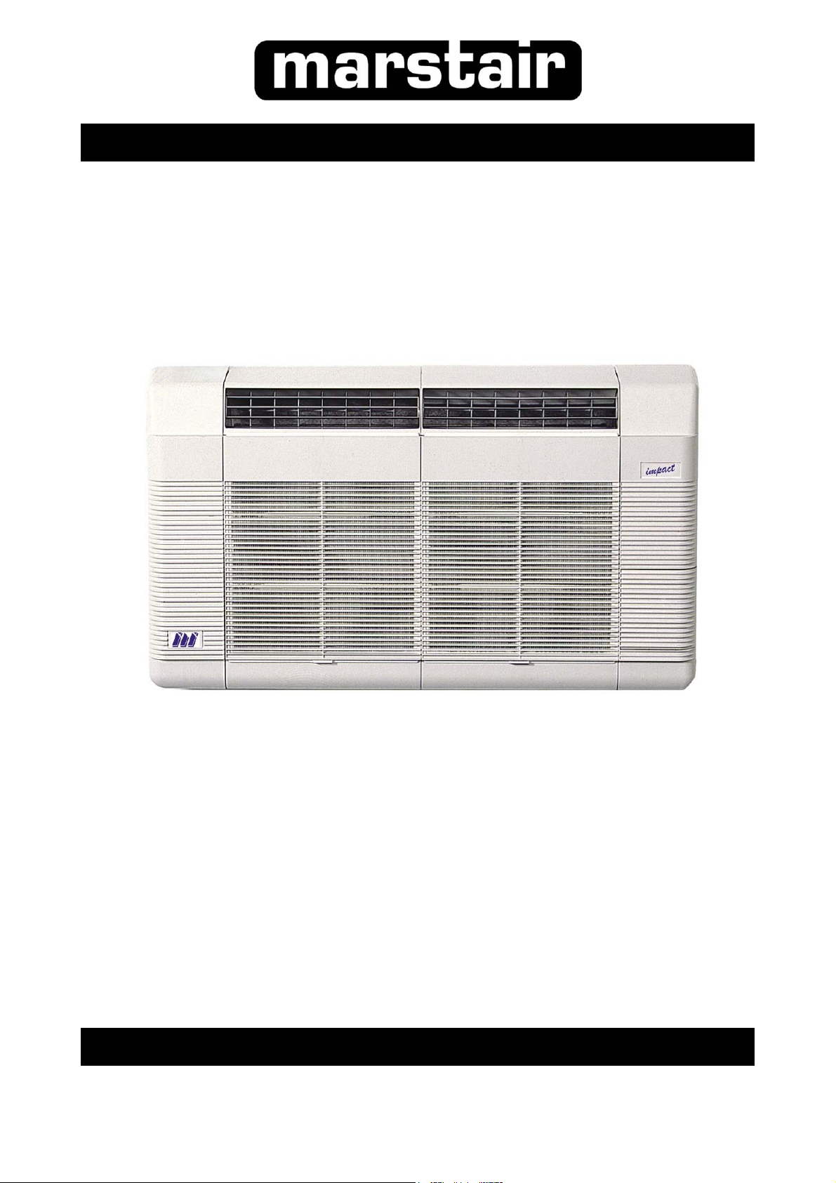
IMPACT / IMPACT E WALL MOUNTED UNITS
TECHNICAL MANUAL
53799173-05
Page 2

Heronhill - for all your Marstair requirements
Tel: 01823 665660
www.heronhill.co.uk
Fax: 01823 665807
INDEX
CONTENTS PAGE
GENERAL. 2
PART NUMBERS, DIMENSIONS & WEIGHTS, FEATURES & ACCESSORIES, UNIT
COMBINATIONS.
SYSTEMS & PERFORMANCE, ELECTRICAL HEATING, AIR FLOWS. 4
SOUND POWER AND SOUND PRESSURE LEVELS, ELECTRICAL DATA. 5 – 6
ELECTIRAL LOADS. 6 - 7
UNIT INSTALLATION. 7 - 9
APLLICATION, RESTRICTORS. 10 - 11
PIPE CONNECTIONS. 12
ELECTRICAL CONNECTIONS. 13
E REMOTE CONTROLLER. 14
WIRING DIAGRAMS. 15 - 18
EXPLODED VIEW, COMPONENT IDENTIFICATION.
3
19
GENERAL
1. TEV Ltd recommend that personnel working on this equipment be skilled and fully conversant with
the appropriate Air Conditioning, Refrigeration and Electrical practices and have sound knowledge
of current Industrial Safe Working practices.
2. The impact wall mounted range of split systems comprises of 537 series impact wall mounted
indoor units, 550 series condensing units and 551 series heat pump outdoor units, or 542 series
ducted condensing units and 543 series electronic ducted heat pump units. By choosing
appropriate combinations the installer can provide:
a. Air conditioners with a cooling range of 1.6 – 9.9 kW.
b. Heatpump systems with a cooling range of 2.0 – 8.6kW, and a heating range of
1.9 – 9.4kW with an outdoor temperature of minus 1°C.
3. These units contain live electrical components, moving parts and refrigerant under pressure.
Always site out of reach of children and protect from vandalism.
4. The data plate only gives information for the impact unit. For system details add input power and
current of indoor and outdoor unit, including any heater load.
2/20
53799173-05
Page 3
Heronhill - for all your Marstair requirements
Tel: 01823 665660
www.heronhill.co.uk
Fax: 01823 665807
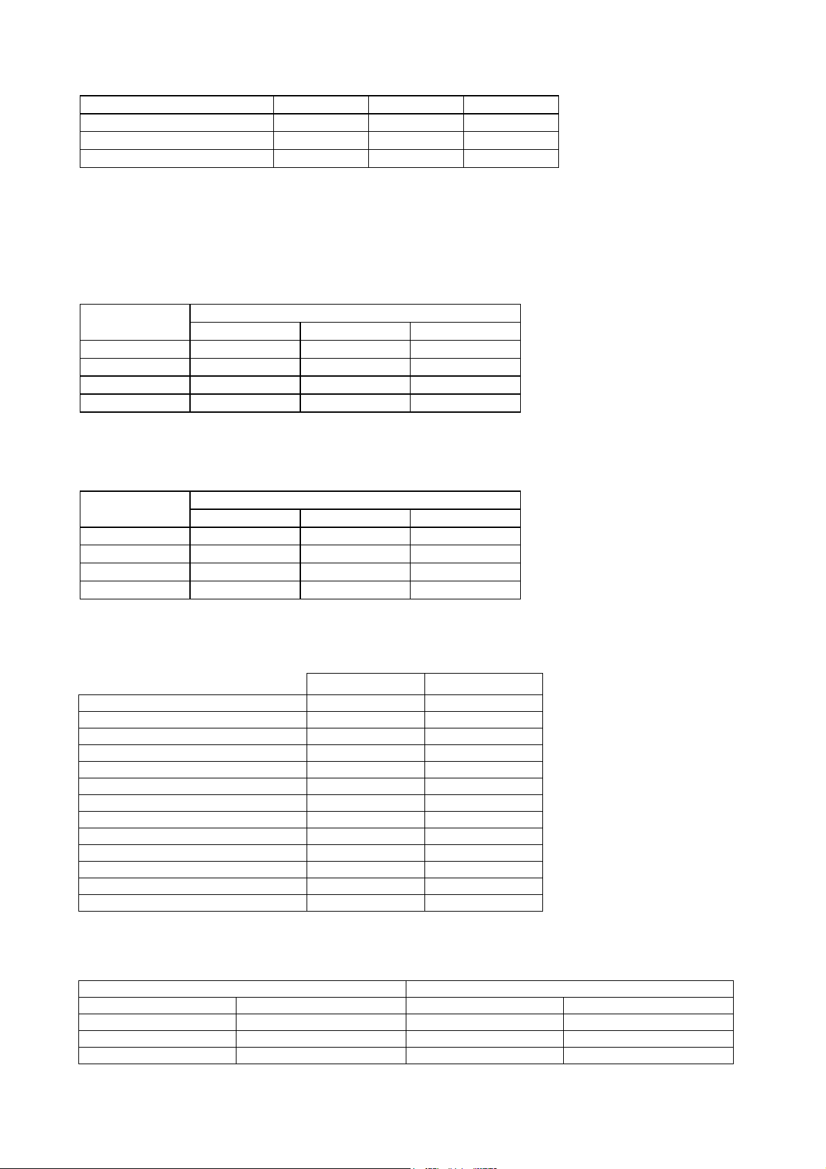
PART NUMBERS
Electromechanical Models
Part Number
Electronic Models
Part Number
IMPACT 20 IMPACT 40 IMPACT 60
53700001 53700002 53700003
IMPACT 20E IMPACT 40E IMPACT 60E
53700011 53700012 53700013
DIMENSIONS AND WEIGHTS (for dimensions, weights and sizes of outdoor units refer to outdoor
unit technical manual
)
IMPACT INDOOR UNITS (unpacked)
Model
HEIGHT mm 490 490 490
WIDTH mm 550 850 1150
DEPTH mm 204 204 204
WEIGHT kg 14 18 24
20(E) 40(E) 60(E)
IMPACT
IMPACT INDOOR UNITS (packed)
Model
HEIGHT mm 616 616 616
WIDTH mm 720 1020 1320
DEPTH mm 290 290 290
WEIGHT kg 16 20 27
40(E) 60(E)
20(E)
IMPACT
FEATURES / ACCESSORIES
Adjustable air deflectors
De-ice thermostat
Electric heating
Electromechanical thermostat
3 fan speeds
Remote hard wired control --Remote infrared control --Network / Multisplit control --Programmable timer
Condensate pump
Long life washable filter
Flame retardant material
High or low level mounting
KEY: * = factory/site option STD = standard --- = not available
IMPACT IMPACT (E)
STD STD
* STD
* *
STD
STD STD
* STD
* *
STD STD
STD STD
STD STD
---
STD
STD
STD
UNIT COMBINATIONS
AIR CONDITIONING SYSTEMS HEAT PUMP SYSTEMS
IMPACT MCU+ / DCU+ IMPACT MHPUE / DHPUE
20 (E) 15 20 (E) 15
40 (E) 30 / 40 40 (E) 30
60 (E) 40 / 60 60 (E) 50
3/20
53799173-05
Page 4
Heronhill - for all your Marstair requirements
Tel: 01823 665660
www.heronhill.co.uk
Fax: 01823 665807
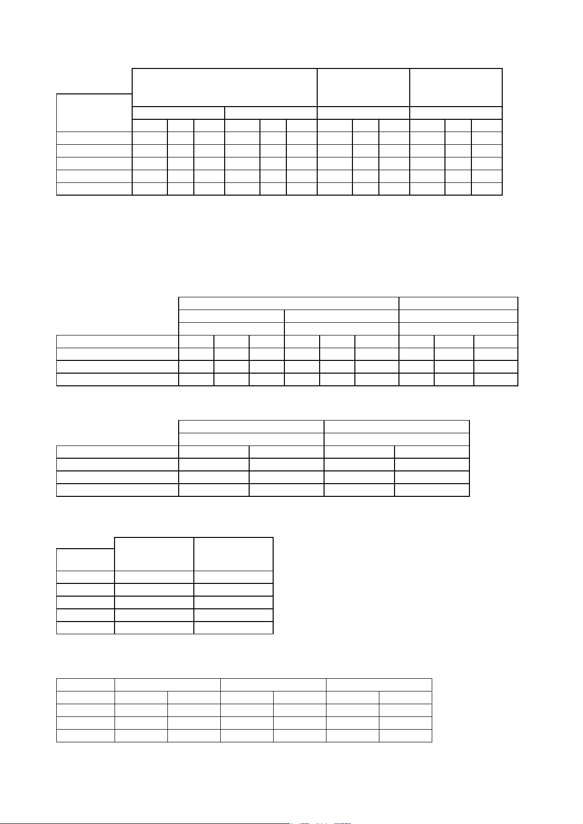
AIR CONDITIONER SYSTEMS AND PERFORMANCE (kw)
IMPACT + MCU+
or DCU+
20(E) + 15 1.4 0.71 1.1 1.9 0.77 1.5 2.1 0.78 1.6 1.6 0.98 1.6
40(E) + 30 2.3 0.77 1.8 3.1 0.83 2.5 3.4 0.84 2.9 2.9 0.96 2.8
40(E) + 40 2.7 0.74 2.0 3.6 0.78 2.8 4.0 0.78 3.1 3.2 0.98 3.1
60(E) + 40 3.0 0.78 2.3 3.9 0.88 3.5 4.4 0.86 3.8 3.7 0.99 3.7
60(E) + 60 3.7 0.74 2.7 5.1 0.80 4.1 5.4 0.81 4.4 4.4 0.98 4.3
MIN SPEED EVAP MAX SPEED EVAP MAX SPEED EVAP MAX SPEED EVAP
TOTAL SHR SENS TOTAL SHR SENS TOTAL SHR SENS TOTAL SHR SENS
UK CONDITIONS
ROOM 21°C/15°C
AMBIENT 27°C/19°C
NEMA (EUROVENT)
ROOM 27°C/19°C
AMB 35°C/24°C
TROPICAL
ROOM 29°C/19°C
AMB 46°C/24°C
For MED speed duties, interpolate between MIN speed and MAX speed duties.
Rating conditions are to BS2852: Part 1: 1982: UK condition C; NEMA condition A; Tropical condition B.
HEAT PUMP PERFORMANCE
1. Cooling, (MAX speed outdoor unit fan). (kW)
IMPACT / MHPUE or DHPUE TOTAL SHR SENS TOTAL SHR SENS TOTAL SHR SENS
20E - 15 1.2 0.75 0.9 1.7 0.81 1.4 2.0 0.78 1.6
40E – 30 2.2 0.78 1.7 3.0 0.83 2.5 3.3 0.85 2.8
60E - 50 3.5 0.72 2.6 4.8 0.82 3.9 5.3 0.81 4.3
ROOM 21°C/15°C AMBIENT 27°C/19°C R27°C/19°C A35°C/24°C
MIN SPEED INDOOR FAN MAX SPEED INDOOR FAN MAX SPEED INDOOR FAN
UK CONDITIONS NEMA (EUROVENT)
2. Heating, (room 20°C / 12°C, outdoor unit fan at MAX speed). (kW)
IMPACT / MHPUE or DHPUE kW COP kW COP
20E – 15 2.3 2.23 1.9 2.00
40E – 30 4.0 2.78 3.1 2.30
60E - 50 5.4 2.60 4.3 2.20
HEATING OUTPUT AT 7°C AMBIENT HEATING OUTPUT AT -1°C AMBIENT
MAX SPEED INDOOR FAN MAX SPEED INDOOR FAN
OPTIONAL ELECTRIC HEATING
IMPACT
at 230V 50Hz
(kW)
at 240V 50Hz
(kW)
20(E) 0.7 0.8
40(E) 1.4 1.5
60(E) 2.1 2.25
80(E) 2.75 3.0
100(E) 3.2 3.5
AIRFLOWS IMPACT UNITS
MIN Speed MED Speed MAX Speed
IMPACT CFM M³/S CFM M³/S CFM M³/S
20(E) 125 0.06 170 0.08 210 0.10
40(E) 275 0.13 345 0.16 420 0.20
60(E) 360 0.17 440 0.21 645 0.30
4/20
53799173-05
Page 5
Heronhill - for all your Marstair requirements
Tel: 01823 665660
www.heronhill.co.uk
Fax: 01823 665807
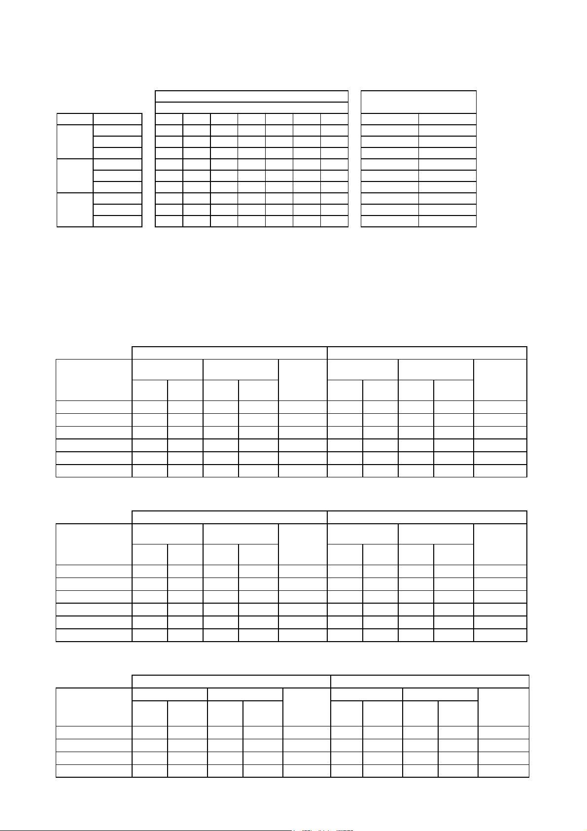
SOUND POWER AND SOUND PRESSURE LEVELS
IMPACT UNITS
SOUND POWER LEVELS
MODEL SPEED
20 Min
40 Min
60 Min
Med
Max
Med
Max
Med
Max
125 250 500 1K 2K 4K dBA
42.1 48.6 52.2 47.4 40.7 34.8 52.1
45.5 51.3 54.6 51.8 45.3 39.1 55.6
48.3 53.9 57.2 55.2 48.8 42.9 58.7
45.9 51.4 53.3 51.3 46.9 44.6 55.6
47.5 53.1 55.4 53.5 48.9 45.8 57.6
50.7 55.6 58.0 56.6 51.9 48.0 60.4
56.4 51.1 52.8 50.2 47.2 42.4 55.2
56.6 53.0 55.4 52.9 48.6 43.6 57.3
58.0 57.8 60.3 58.9 53.7 48.9 62.6
Sound Power Levels were obtained in full conformity with BS 4196: Part 5: 1981. Quantities are shown in dB
with a standard reference of 1 pW.
Sound Pressure Levels are dB relative to 2 x 10
conditions and are quoted as an average of all points on a hemisphere of a radius of 3m away from the
centre of the unit.
ELECTRICAL DATA
R407C AIR CONDITIONING SYSTEMS (MCU+)
MODEL
COMBINATION
IMPACT + MCU+ kW kW AMPS AMPS AMPS kW kW A/PH A/PH* A/PH
20(E) + 15 0.9 0.9 6.4 4.0 23 -- -- -- -- --
40(E) + 30 1.4 1.7 8.7 7.6 37 1.4 1.7 4.5 7.6 19
40(E) + 40 1.6 1.7 10.8 7.6 51 1.6 1.7 5.7 7.6 23
60(E) + 40 1.6 2.5 10.9 11.1 51 1.6 2.5 5.8 11.1 23
60(E) + 60 2.5 2.5 10.2 10.8 62 2.5 2.5 4.6 10.8 33
Single Phase Supply 230Volts - 50Hz Three Phase Supply 400Volts - 50Hz
INPUT FULL LOAD AMPS INPUT FULL LOAD AMPS
Cooling Heating Cooling Heating
R407C AIR CONDITIONING SYSTEMS (DCU+)
MODEL
COMBINATION
IMPACT + DCU+ kW kW AMPS AMPS AMPS kW kW A/PH A/PH* A/PH
20(E) + 15 1.3 0.9 6.0 4.0 25 -- -- -- -- --
40(E) + 30 1.8 1.7 8.4 7.6 37 1.8 1.7 3.6 7.6 19
40(E) + 40 2.3 1.7 10.6 7.6 51 2.3 1.7 4.8 7.6 24
60(E) + 40 2.3 2.5 10.7 11.1 51 2.3 2.5 4.9 11.1 24
60(E) + 60 3.1 2.5 14.3 11.1 61 3.1 2.5 6.0 11.1 26
Single Phase Supply 230Volts - 50Hz Three Phase Supply 400Volts - 50Hz
INPUT FULL LOAD AMPS INPUT FULL LOAD AMPS
Cooling Heating Cooling Heating
R407C HEAT PUMP SYSTEMS (MHPUE)
MODEL
COMBINATION
IMPACT + MHPUE kW kW AMPS AMPS AMPS kW kW A/PH A/PH* A/PH
20(E) + 15 0.9 1.7 6.4 9.9 31 -- -- -- -- --
40(E) + 30 1.4 3.0 8.7 15.7 42 1.4 3.0 4.5 11.5 26
60(E) + 50 2.1 4.5 9.5 19.9 61 2.1 4.5 4.6 15.0 33
* Max Phase
Single Phase Supply 230Volts - 50Hz Three Phase Supply 400Volts - 50Hz
INPUT FULL LOAD AMPS INPUT FULL LOAD AMPS
STD.
MODEL
+ ELECT
Heating
MODEL
STD.
Frequency Hz
-5
N/m2 and are calculated from the results under anechoic
+ ELECT
Heating
SYSTEM
MAX.
STARTING
CURRENT
SYSTEM
MAX.
STARTING
CURRENT
SYSTEM
MAX.
STARTING
CURRENT
5/20
SOUND PRESSURE LEVELS
dBA NC
31.6 26
35.1 30
38.2 33
35.1 30
37.1 32
39.9 35
34.7 27
36.8 31
42.1 37
Cooling Heating Cooling
Cooling Heating Cooling
STD.
MODEL
+ ELECT
Heating
MODEL
STD.
Heating
Heating
+ ELECT
Heating
SYSTEM
MAX.
STARTING
CURRENT
SYSTEM
MAX.
STARTING
CURRENT
SYSTEM
MAX.
STARTING
CURRENT
53799173-05
Page 6
Heronhill - for all your Marstair requirements
Tel: 01823 665660
www.heronhill.co.uk
Fax: 01823 665807
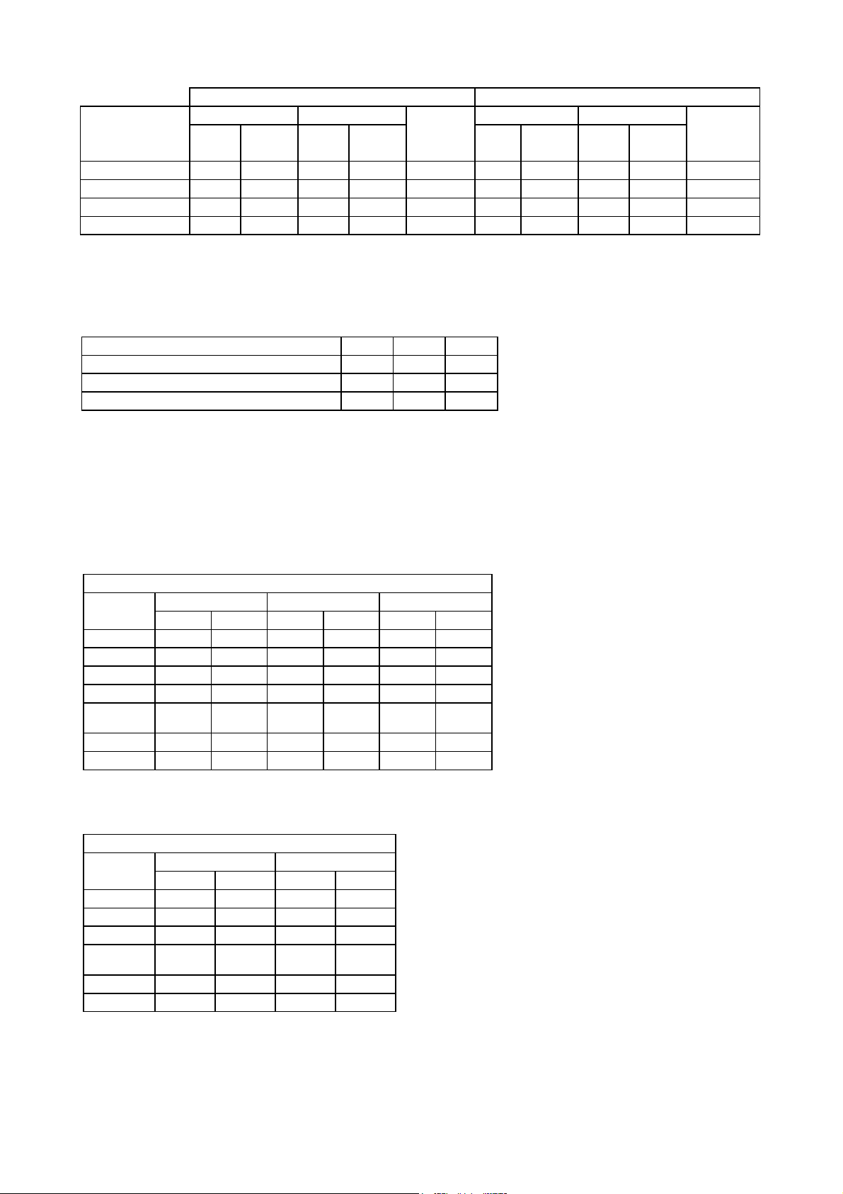
R407C HEAT PUMP SYSTEMS (DHPUE)
MODEL
COMBINATION
IMPACT + DHPUE kW kW AMPS AMPS AMPS kW kW A/PH A/PH* A/PH
20(E) + 15 1.3 2.2 4.6 8.1 23 -- -- -- -- --
40(E) + 30 1.8 3.5 9.1 16.1 46 1.7 3.5 3.9 10.9 28
60(E) + 50 2.5 5.0 11.7 22.1 65 2.5 5.0 5.3 15.7 38
Single Phase Supply 230Volts - 50Hz Three Phase Supply 400Volts - 50Hz
INPUT FULL LOAD AMPS INPUT FULL LOAD AMPS
STD.
MODEL
+ ELECT
Heating
MODEL
STD.
* Max Phase
ELECTRICAL LOADS (230V 50Hz 1Ph, A or 400V 50Hz 3PhN, A/Ph)
IMPACT
FAN MOTOR 0.2 0.3 0.4
ELECTRIC HEATER (AIR COND.) 3.5 7 10.4
ELECTRIC HEATER (HEAT PUMPS) 3.5 7 10.4
FUSES
The system and its supply/interconnecting wiring must be protected by fuses, preferably High Rupture
Current (HRC) motor rated types (EN60269) or miniature circuit breakers (EN60898) or local codes having
similar time lag characteristics, that allow starting of the compressor yet still afford close overcurrent
protection under running conditions. The ratings below are for HRC motor rated fuses.
FUSES FOR SYSTEMS WITH SINGLE PHASE (230V) OUTDOOR UNITS (A)
IMPACT (E)
MCU+ or
DCU+
15
30
40
60
MHPUE or
DHPUE
30
50
20 40 60
S H S H S H
16 16
16 16
20 20 20 20
20 20
S H S H S H
10 16
20 20
S = Standard H = Heaters
FUSES FOR SYSTEMS WITH THREE PHASE (400V) OUTDOOR UNITS (A/Ph)
IMPACT (E)
MCU+ or
DCU+
30
40
60
MHPUE or
DHPUE
30
50
S = Standard H = Heaters
40 60
S H S H
10 10
10 10 16 16
10 16
S H S H
10 16
10 16
SYSTEM
+ ELECT
Heating
20E 40E 60E
MAX.
STARTING
CURRENT
6/20
STD.
MODEL
+ ELECT
Heating
MODEL
STD.
+ ELECT
Heating
SYSTEM
MAX.
STARTING
CURRENT
53799173-05
Page 7
Heronhill - for all your Marstair requirements
Tel: 01823 665660
www.heronhill.co.uk
Fax: 01823 665807
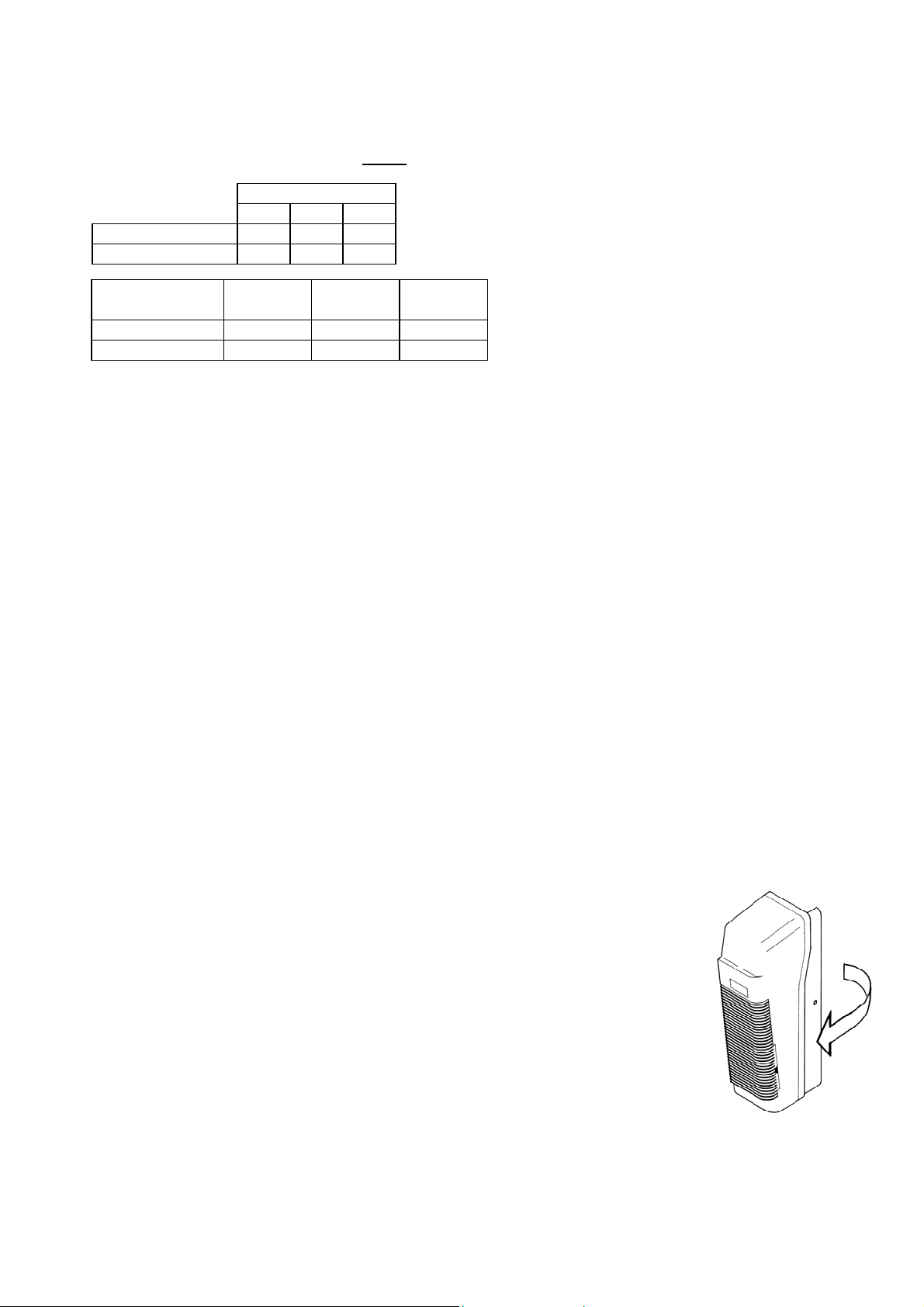
SEPARATE SUPPLIES TO ELECTRONIC INDOOR AND OUTDOOR UNITS (A)
HEAT PUMP SYSTEMS ONLY
It is recommended that systems using electronic indoor AND outdoor units should be independently fused.
NOTE THAT THESE SUPPLIES MUST BE TAKEN FROM THE SAME PHASE
1Ph Cool Only
1Ph Cool and Heat
OUTDOOR UNIT
1Ph (A)
3Ph (A/Ph)
MHPUE 15
DHPUE 15
IMPACT E
20 40 60
5 5 5
5 10 10
MHPUE 30
DHPUE 30
10 16 20
--- 10 10
IMPACT (E) WALL MOUNTED UNIT INSTALLATION
The installer supplies:
• 4 off M6 (or equivalent strength) Rawlbolt shields, bolts and washers.
• Fully insulated refrigeration pipework.
• All mains wiring with suitable isolation; Interconnecting wires for indoor and outdoor units.
• Condensate drain (minimum 10mm bore for gravity drain, 8mm bore for condensate pump
drain).
• Two spanners for securing the flare connectors.
• A cross-headed screwdriver for releasing the end cover fasteners.
• A 4 or 5mm Allen key for opening the outdoor/ducted unit valves (depending on valve type).
• Method for securing solid sheathed cables if these are used.
Unpacking
Carefully unfasten the banding and lift off the outer cardboard carton sleeve.
The following are supplied:
• IMPACT unit (in protective sleeve, held between two polystyrene end caps).
• A cardboard sleeve containing two pipe assemblies complete with insulation and two cable
glands suitable for flexible, p.v.c. sheathed cable.
• A wall-mounting bracket also held between the two polystyrene end caps.
• Envelope containing operating instructions to be left with the end user.
• IMPACT E models also have an electronic remote control assembly incorporating the infrared
controller, wall mounting bracket, two screws and wall plugs and a battery.
1 Remove and place to one side the cardboard sleeve containing the two pipe
assemblies, (and remote control assembly on IMPACT E models).
2 Lift the IMPACT unit from the inner cardboard sleeve complete with the two
polystyrene end caps; (this will require 2 people for sizes 60 to 100).
3 Remove the wall-mounting bracket and carefully remove the two polystyrene end
caps and the protective sleeve from the IMPACT unit.
4 Remove both end covers by removing the self-tapping screws, one on each end
trim. By pulling the end covers sharply they can be removed from the backpanel
and fascia.
MHPUE 50
DHPUE 50
7/20
53799173-05
Page 8
Heronhill - for all your Marstair requirements
Tel: 01823 665660
www.heronhill.co.uk
Fax: 01823 665807
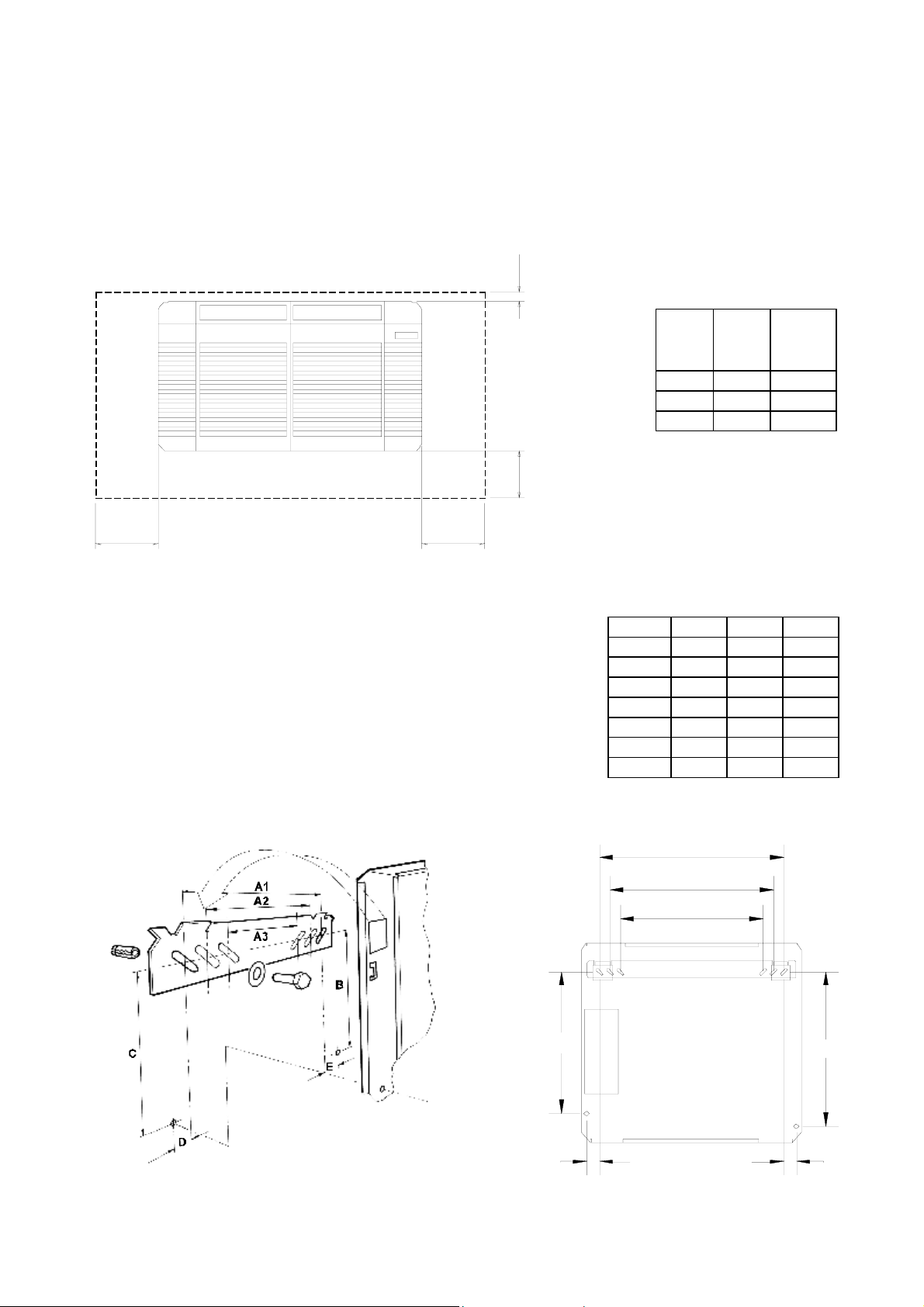
Chassis Mounting
NOTE: It is generally easier to fit kits prior to mounting the unit and connecting the pipework.
It is essential to fit a heater kit at this stage if right hand side access will be limited
to less than the unit width.
1 Ensure that the wall is flat and will support the operating weight of the unit, (see below)
.
2 Ensure that sufficient access is left around the unit for future kit fitting, servicing and
maintenance.
LEFT
HAND
WALL
200mm
minimum
*Removal or replacement of heater elements requires a clearance at the right hand side equal to the
length of the unit
3 Mark out the two required top-hole centres as shown in Fig.
4 Hang the unit on the two protrusions from the wall mounting
INST ALLATION AN D SERVICE ACCESS
CEILING
RIGHT
HAND
WALL
FLOOR
200mm*
(*Unless heaters fitted)
minimum
2, (note that the top of the IMPACT unit will be
approximately 100mm above the level of the hole
centres). Drill to suit M6 Rawlbolt shields or equivalent
strength fasteners. Secure the wall-mounting bracket to the
upper two holes ensuring that it is level.
bracket and, ensuring that the unit is level, mark out and drill
the lower two holes and secure the unit to the wall.
30mm
minimum
To allow
top box
removal
*Includes all kits and refrigerant
150mm
minimum
(screwdriver
access)
Model
20(E) 14 15
40(E) 18 21
60(E) 24 25
Model 20E 40E 60E
A1 445 745 1045
A2 395 695 995
A3 345 645 945
B 370 370 370
C 340 340 340
D 31 31 31
E 29 29 29
Weight
kg
Operating
Weight
kg
8/20
C
D
A1
A2
A3
B
E
53799173-05
Page 9
Condensate Removal
A
Heronhill - for all your Marstair requirements
Tel: 01823 665660
www.heronhill.co.uk
Fax: 01823 665807
Condensate collects in a drip tray along the full length of the coil.
An outlet pipe is provided at the rear left hand end of the tray for connection to a pipe for gravity drain.
Slide the outlet pipe from the clip and exit the unit vertically through the hole in the backpanel or base tray.
The drain stub has a 14mm o.d. barb and is supplied with connector and a short length of 6.35mm i.d. hose
For connection to a 10-12mm i.d. flexible hose, remove the hose and connector supplied and connect
directly to the stub.
Ensure that the drain pipe is kept below the rim of the drip tray along its entire length.
Once a gravity drain has been installed, check to ensure that the pipe is not kinked and that correct drainage
occurs by slowly filling the drip tray with water.
A condensate pump kit (incorporating overflow protection) can be fitted within the unit to enable a lift of up to
5m.
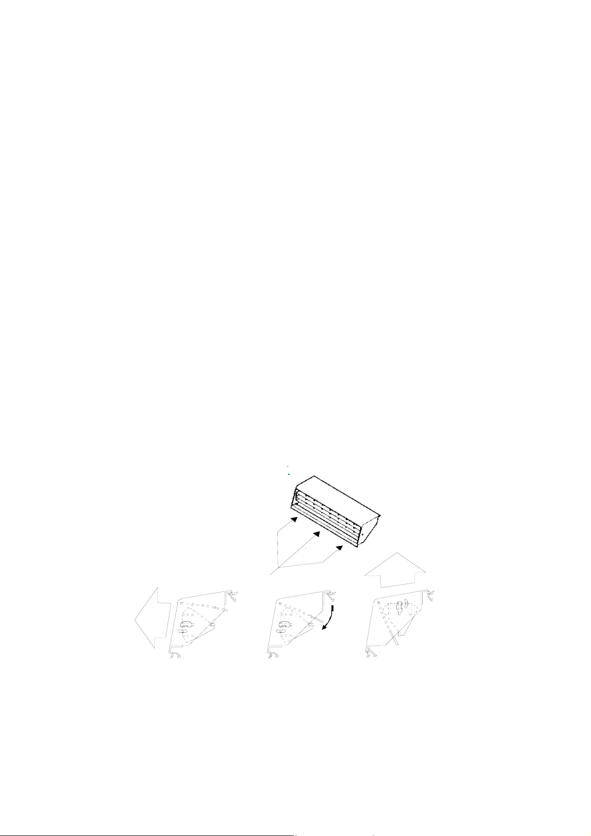
Air Deflection
Air deflection is set by manually adjusting the vanes. The unit is supplied with front discharge but can be
changed to top discharge as follows.
1 Remove the filters.
2 Remove the end covers.
3 Using a screwdriver or thin bladed tool, release the three tabs at the bottom of the top box; these are
directly below the centre and two end vertical vanes.
4 Lift the top box assembly from the unit.
5 By gently flexing the top box sides from the rear, transfer the deflector plate from the upper to the
lower two fixing holes.
6 Rotate the top box assembly and refit to give top discharge.
AIR
DEFLECTOR AS
SUPPLIED FOR
FRONT DISCHARGE
TABS
MOVE DEFLECTO R
TO ALTERNA TIVE
POSITION
9/20
IR
TURN TOP BOX
THROUGH 180° AND
SNAP IN TO SU IT
TOP DISCHARGE
53799173-05
Page 10
APPLICATION
Heronhill - for all your Marstair requirements
Tel: 01823 665660
www.heronhill.co.uk
Fax: 01823 665807
1 To maximise performance, pipe runs should be kept as short as possible, avoiding sharp bends.
However, individual pipe runs to a maximum of 80m, including 20m lift, are permissible provided good
refrigeration practice is followed.
Published performance duties are based on 7.5m pipe runs. Correctly sized pipes for each installation,
and fitting the correct expansion orifice (restrictor) will result in no significant loss of capacity on
extended pipe runs.
a) Pipe sizes are based on: Minimum of 3.8 m/s (750 fpm) suction gas velocity for horizontal or downflow.
Minimum of 7.6 m/s (1500 fpm) suction gas velocity for upflow.
Maximum of 15.2 m/s (3000 fpm) suction gas.
b) Where vertical risers exceed 3m, oil traps must be formed in the pipe. This will help ensure that oil
returns to
the compressor. Typically fit an oil trap every 3m with a trap at the bottom of the riser.
2 Add 25 grams of polyolester (POE) oil for every 350 grams of charge added to systems with pipe runs
exceeding 25m, up to a maximum of 300 grams; preferably by slowly pumping into the suction side with
the unit running, after charging the system.
3 The maximum pipe lengths to be used for each pipe size and outdoor unit are shown in the table below.
Use of these sizes and lengths is recommended in order to achieve optimum system performance.
4 In calculating equivalent lengths of pipe runs, the effect of bends and fittings must be taken into
account. The table below covers the fittings most likely to be encountered in this type of installation.
The equivalent lengths of all the fittings in a particular pipe run must be added together and the total
added to the actual length of pipe in the run, in order to calculate the total equivalent length.
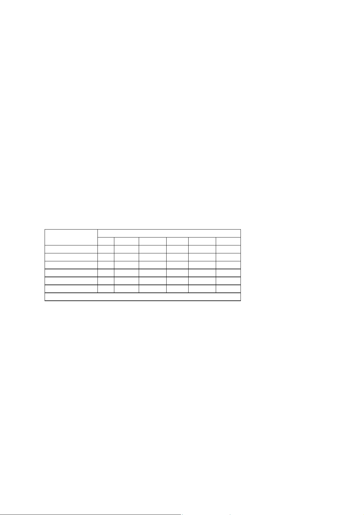
FITTING LOSSES, in equivalent straight lengths of pipe (metres).
Fitting 3/8 1/2 5/8 3/4 7/8 1-1/8
45° Bend
90° Bend R/d = 1
90° Bend R/d = 1.5
180° Bend C/d =
180° Bend C/d =
90° Elbow
R = Radius of bend d = Diameter of tube C = Centres of
0.12 0.15 0.18 0.21 0.24 0.3
0.37 0.43 0.49 0.55 0.61 0.79
0.24 0.27 0.30 0.37 0.43 0.52
0.73 0.91 1.10 1.28 1.46 1.83
0.46 0.55 0.64 0.76 0.85 1.07
0.67 0.85 1.04 1.25 1.46 1.89
Pipe Size (outside diameter in inches)
5 Use the shortest possible route, avoiding sharp bends
.
6 Fully insulate both the suction and expansion lines, including the expansion device, since both lines
may sweat.
10/20
53799173-05
Page 11
RESTRICTOR MATCHES
Heronhill - for all your Marstair requirements
Tel: 01823 665660
www.heronhill.co.uk
Fax: 01823 665807
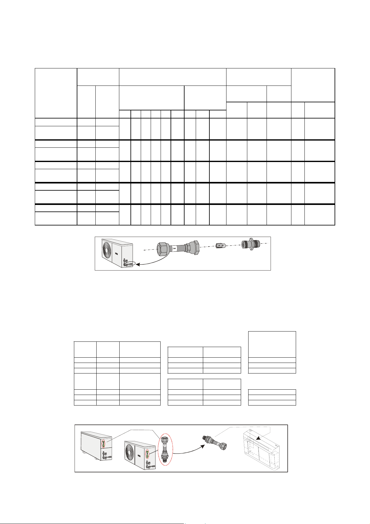
Outdoor units are supplied with cooling restrictors fitted in the expansion assembly; refer to the following
tables for any restrictor changes. Those ticked do not require a change of restrictor.
Where appropriate, the alternative cooling or heating restrictor is supplied with either the indoor or the
outdoor unit
SYSTEM
MATCH
IMPACT 20
DCU+ 15
IMPACT 40
MCU+30/
DCU+ 30
IMPACT 40
MCU+40/
DCU+ 40
IMPACT 60
MCU+40/
DCU+ 40
IMPACT 60
MCU+60/
DCU+ 60
MCU+15/
PIPE CONNS MAXIMUM PIPE RUNS (m) COOLING RESTRICTOR
SUC
3/8
3/8
1/2
1/2
1/2
1/2
5/8
1/2
5/8
5/8
MCU+
UK
033
040
042
042
051
NEMA
035
042
044
044
053
SUCTION
EXP
3/8 1/2 5/8 3/4 7/8 11/8
3/8
7.5 30 50
3/8
3/8
3/8
3/8
3/8
3/8
3/8
3/8
3/8
15 50 80
10 36 80
10 36 80
14 36 80
EXPANSION
3/8 1/2 5/8
50
50 80
7.5 80
7.5 80
7.5 50 80
DCU+
UK +
NEMA
032
039
041
043
050
CHARGE TO
UK
(g)
200
0
140
200
0
ADD
(for 7.5m)
NEMA
(g)
230
60
240
300
635
D
Restrictor / Orifice / Düse
HEAT PUMP SYSTEMS (ALL CONDITIONS)
Heat pumps are supplied with a heating restrictor in an expansion assembly. This must be fitted
close to the indoor unit in the expansion line, (smaller of two connections) arrows pointing in the
direction of the outdoor unit.
(1)
= NO RESTRICTOR CHANGE
MHPUE IMPACT
15 20 033 035 035
30 40 040 042 039
50 60 052 044
DHPUE IMPACT
15 20 032 027
30 40 039 037
50 60 049 044
NEEDED
Cooling restrictor
Fitted to the
outdoor unit
Cooling restrictor
Fitted to the
outdoor unit
DHPUE
MHPUE
Heat pump cooling conditions
UK
CONDITIONS
Heat pump cooling conditions
UK
CONDITIONS
NEMA
CONDITIONS
NEMA
CONDITIONS
Heating restrictor
fitted to the outdoor
expansion assembly
E
11/20
53799173-05
Page 12
PIPE CONNECTIONS
Heronhill - for all your Marstair requirements
Tel: 01823 665660
www.heronhill.co.uk
Fax: 01823 665807
IMPACT UNITS
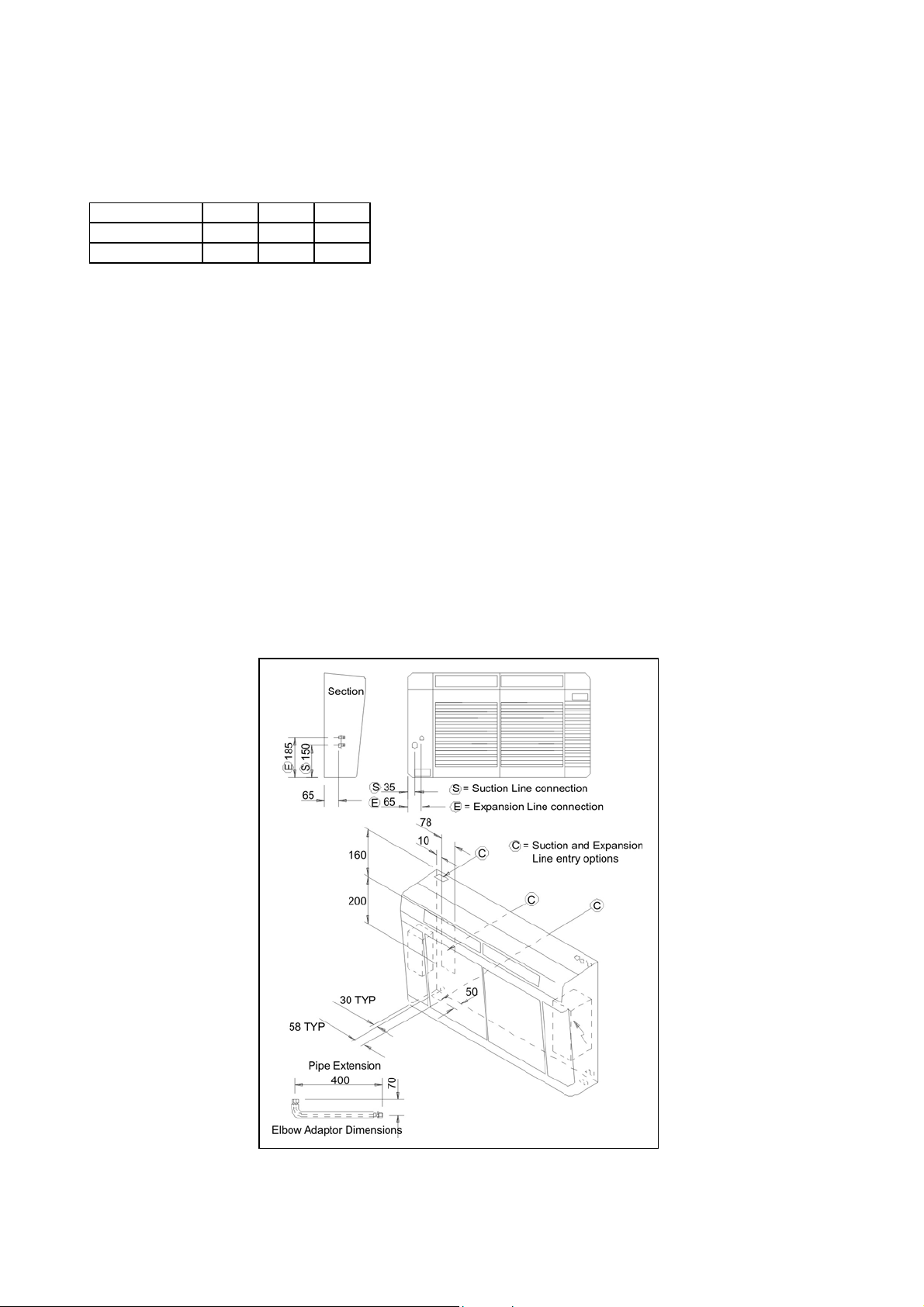
Pipework is terminated at the left hand side of the unit. Two pipe assemblies are supplied loose with flare nut
connectors to enable pipe exit from either the top or bottom of the unit via knockouts. Rear pipe exit is
possible with installer supplied pipework.
Always use two spanners to secure the flare connections to avoid distorting and damaging the pipework.
Pipe flare connections (in inches) are;
IMPACT Model 20(E) 40(E) 60(E)
Expansion Pipe
Suction Pipe
1 If top or bottom pipe exit is required, remove the appropriate knockout in the backpanel flanges.
2 Remove and retain the flare nuts from the coil, (the bonnets should be discarded).
3 Screw the angled ends of the pipe extensions to the male connectors on the coil, ensuring that the
straight ends extend through the knockout.
For pipe exit through the rear of the unit, the installer must supply appropriately flared pipework.
On heat pump systems the IMPACT unit needs to have an expansion assembly fitted; refer to
the next section.
4 Interconnecting pipework should be installed in accordance with good refrigeration practice.
5 Final connection is made to the male flare connectors, either on the pipe extensions (for top or bottom
entry) or directly onto the coil (for rear entry).
3/8 3/8 3/8
3/8 1/2 5/8
6 Care should be taken to ensure that pipe flares are correctly formed and have undamaged seating
surfaces. The use of a little oil on the flaring tool will help. DO NOT FORGET to fit the flare nut onto
the pipe BEFORE flaring it.
7 Make the flare connections to IMPACT using a little refrigeration oil on the mating surfaces. Always
use two spanners in opposing directions to avoid twisting the pipework and damaging the coil
connections.
12/20
53799173-05
Page 13

ELECTRICAL CONNECTIONS
Heronhill - for all your Marstair requirements
Tel: 01823 665660
www.heronhill.co.uk
Fax: 01823 665807
1 Mains, control and interconnecting cables must be supplied and fitted by the installer.
2 Installer wiring must be carried out in accordance with IEE regulations and local codes. Refer to the
interconnecting wiring diagrams on pages 30 to 34.
3 Mains supply cables must be size compatible with the recommended fuse for a given system (see
pages 11 and 12).
4 An all pole isolator switch should be positioned within easy reach of the indoor unit.
5 The equipment must be earthed.
6 Cable clamps for use with stranded cables are supplied in units 15 - 90 and should be used to secure
all incoming/outgoing cables. Installers must supply a method of securing any solid sheathed cables.
ELECTROMECHANICAL SYSTEMS
Systems including an electromechanical unit require a supply to the condensing unit with connecting cables
run to the indoor unit
ELECTRONIC SYSTEMS (DCU+, DHPUE and MHPUE):
It is recommended that systems with electronic indoor AND electronic outdoor units have a supply taken to
the outdoor unit AND a separate supply taken to the indoor unit, which in many cases can be from a
domestic 13 Amp socket, (see fuse ratings on pages 11 and 12), otherwise run a supply to the outdoor unit
with connecting cables run to the indoor unit.
Communication between the indoor and outdoor unit is via a two wire (max. 0.75mm
2
) non-polarised
connection (installer supplied), using cable type RS 485 or equivalent, (or two cores of 00526077, 4 core
cable, available from TEV Ltd).
The cable screen should be secured to ground (earth) at BOTH ends using the clamps provided. Do
not attempt to run the communication in the spare cores of any power carrying cable.
Whenever possible, the communication cable should be run separate from any mains cable.
DATA PLATES
Because of the ability to mix-match indoor and outdoor units, the data plate only gives information on
outdoor units. To obtain the system details, input power and currents from indoor and outdoor units should
be added together. Data plates show basic units with electric heater kit loads shown separately.
FIRE LINK
In order to automatically switch off the fan in the event of a fire, it is necessary to fit an external switch (240V,
3A, closed to run, volt free contact) in series with the small black wire connected to the bottom terminal of the
fuse. This switch should be operated by the building's fire alarm or BMS system.
EVACUATING
1. Connect a vacuum pump to the service ports on the outdoor unit valves and evacuate the
interconnecting pipework and indoor unit to 1000 microns (1 Torr) or better and allow to be held for a
minimum of 15 minutes.
2. If NO additional refrigerant charge is required: Replace the caps on the service ports, (tighten to a
torque of 25NM), and open the valves using a 4 or 5mm Allen key. On electronic units, REMOVE link
JP6 identified by a white label, (otherwise the unit will always run at full speed).
13/20
53799173-05
Page 14
ADDING REFRIGERANT
Heronhill - for all your Marstair requirements
Tel: 01823 665660
www.heronhill.co.uk
Fax: 01823 665807
1 If additional refrigerant charge is required:
After evacuating the indoor unit and interconnecting pipework, open the valves using a 4 or 5mm Allen key. The
high and low side pressures should equalise within a minute.
2 Additional charge for all systems, including heat pumps, should be introduced with the system in the AIR
CONDITIONING MODE.
3 Additional charge should be introduced through the Schrader valve on the indoor unit or the service port on the
suction service valve on the outdoor unit (see charging section overleaf to calculate the weight).
4 DCUE, DHPUE and MHPUE are supplied with link JP6 fitted on the outdoor unit pcba; this allows additional
charging and overrides alarms during the charging process. With both units powered, the DCUE, DHPUE or
MHPUE fans will run at high speed and IMPACT E indoor fans will run at maximum speed. When JP6 is linked, the
infrared handset is inoperative.
NOTE: MCU+ units are fitted with head pressure control; before charging, isolate the unit and transfer the blue
5 Ensure that the refrigerant being added is the same refrigerant that the system was originally charged with.
6 If a manual HP cutout is fitted, ensure that the reset button is depressed.
7 On DCUE, DHPUE and MHPUE models a random start delay of up to 1 minute occurs when mains is first applied.
A 3 minute delay occurs between successive compressor operations on all systems incorporating DCUE, DHPUE
and MHPUE units, or MCU(+) units fitted with a 3 minute timer kit.
8 Run the system for a few minutes to allow it to stabilize. Where possible, charge to a sweat line on the evaporator.
Typical suction pressures on short lines at UK conditions, with high speed evaporator fan, low speed condenser
fan (commissioning speed for DCUE, DHPUE and MHPUE), should be; Electromechanical Comfort Systems
approx. 4.4 bar (65 psig); Electronic Comfort Systems approx. 3.8 bar (55 psig); Heat Pump Systems approx. 4.0
bar (58 psig).
Care should be taken when the compressor is first started in the field to ensure that the system is not overcharged,
in which case liquid return to the compressor could result.
9 On DCUE, DHPUE and MHPUE units, once refrigerant has been added, REMOVE link JP6, identified by a white
label (otherwise the unit will always run at full speed).
10. On MCU+ units,return the blue wire from 1 to 4.
WHEN INSTALLATION HAS BEEN COMPLETED - CHECK :-
1.
2.
3. All bolts are secure and that the fan rotates freely.
CHARGING
All pipe work and joints for leakage.
All pipe w
ork and fittings for insulation.
IMPACT WALL MOUNTED SYSTEMS - pipe runs below 7.5m.
Each outdoor unit is charged with R22 or R407C as shown on page 18.
Where additional refrigerant is needed this is shown on P18. Additional oil is not required.
IMPACT WALL MOUNTED SYSTEMS - pipe runs over 7.5m.
For pipe runs over 7.5m, extra refrigerant and oil must be added to the system by the installation engineer as
shown on page 18 PLUS additional refrigerant and oil for each metre over 7.5m, based on the following:
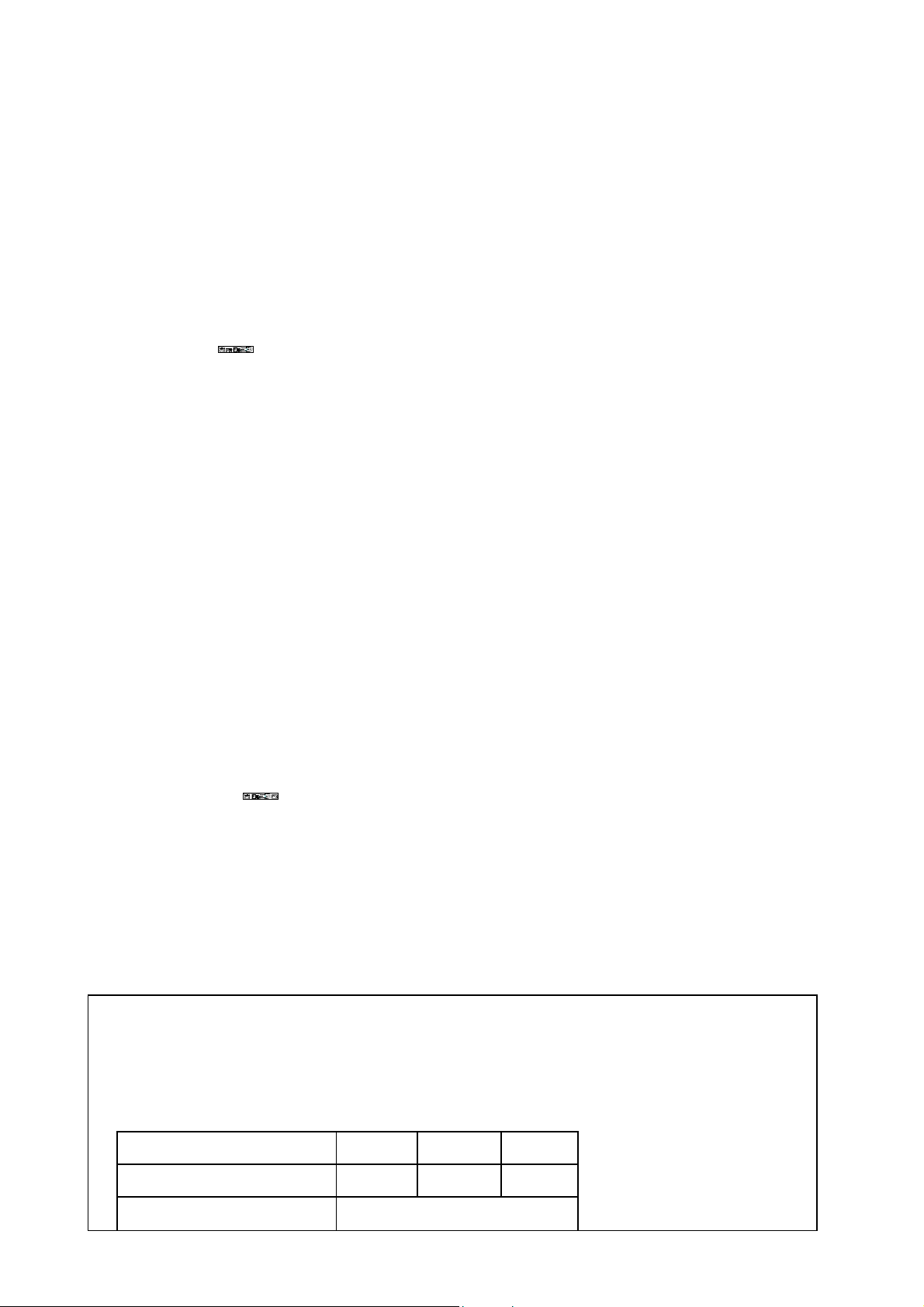
Expansion line size. 3/8 1/2 5/8
Additional refrigerant (g/m) 16 30 48
Additional oil 25g per 350g of additional refrigerant to a
maximum of 300g
14/20
53799173-05
Page 15
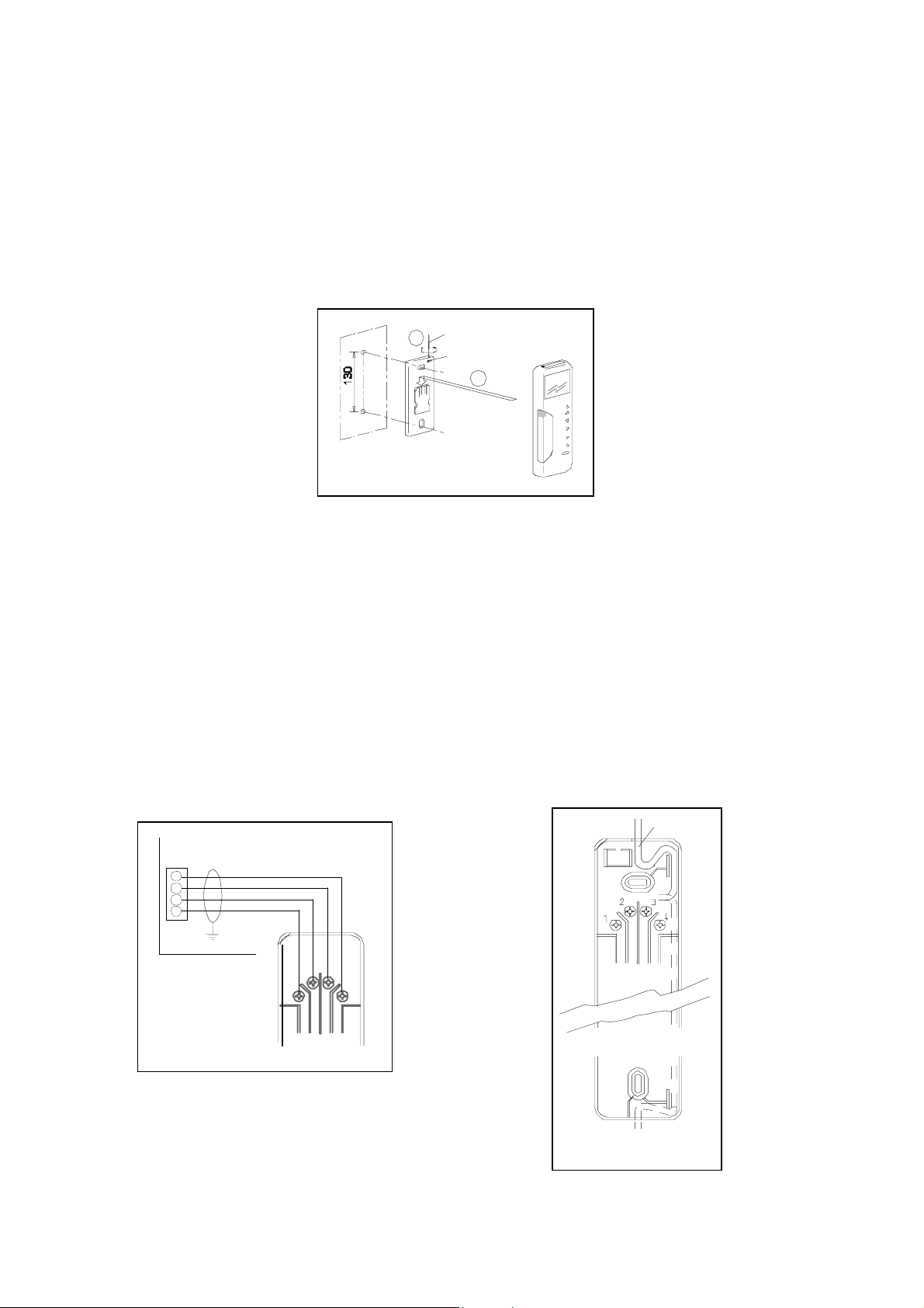
INSTALLATION of the IMPACT E REMOTE CONTROLLER
OU
G
OU
G
Heronhill - for all your Marstair requirements
Tel: 01823 665660
www.heronhill.co.uk
Fax: 01823 665807
IMPACT E indoor units are supplied with a remote controller, wall mounting bracket, PP3 (9 volt) battery,
screws and wall plugs.
The controller either operates remotely by infrared signals, when the bracket may be used to park the
controller for convenience, or may be hard wired to the unit (via the wall mounting bracket) in applications
where infrared is inappropriate, e.g., high lighting level, no direct line of sight etc.
1. Infrared operation
Open the battery cover at the bottom rear of the controller by sliding out and hinging up, push the
polarised connector onto the battery, slot into the controller and close the cover. The controller is now
ready for operation as stated in the user handbook.
For convenience, the wall-mounting bracket may be secured to a wall and used to park the controller.
SCREWDRIVER
SCREWDRIVER
2
2
LOCK I NG CA M
LOCK I NG CA M
1
1
2. Hard wired
Use four core screened cable available from TEV Ltd in 100m drums, part number 00526117. The
screen should be clamped to ground in the IMPACT E unit but NOT connected at the wall bracket end.
NOTE: Great care should be taken to ensure that the wiring is correct, refer to the diagram
below
The cable should be connected prior to mounting the bracket, taking great care to ensure that the 4
contact blades remain free to exert spring pressure on the handset terminals.
Secure the bracket to the wall by drilling two 6mm diameter holes in the positions shown, inserting the
wall plugs and securing with the two screws provided. Attach the controller to the bracket ensuring that it
is pushed down firmly.
If required, the controller may be locked into position by rotating the cam at the top of the bracket with a
small screwdriver. The controller is now ready for operating as stated in the user handbook. The
controller does not require a battery when this method is used.
4
4
JP15
JP15
+
+
EARTH AT
EARTH AT
UNIT END
UNIT END
ONLY
ONLY
CABLE
CABLE
ROUTING
ROUTING
-
-
1
1
2
2
3
Ensure that cables
Ensure that cables
are connected cor rect ly
are connected cor rect ly
ie 1 - 1
ie 1 - 1
2 - 2
2 - 2
3 - 3
3 - 3
4 - 4
4 - 4
3
4
1
1
4
BRACKET VIEWED
BRACKET VIEWED
FROM THE REAR
FROM THE REAR
Ensure cables are correctly connected
15/20
ALTERNATIVE CABLE
ALTERNATIVE CABLE
TIN
TIN
R
R
53799173-05
Page 16
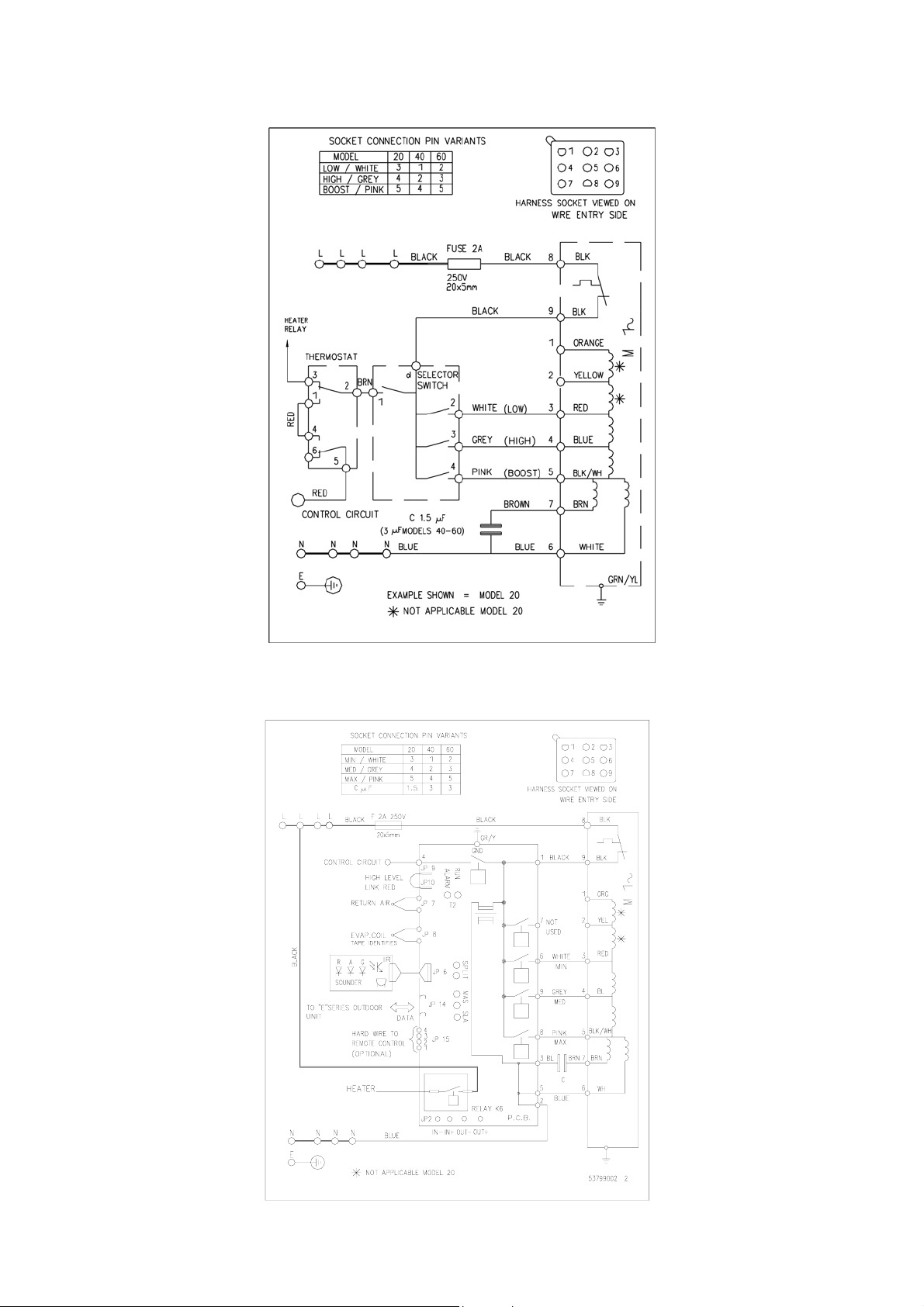
WIRING DIAGRAMS
Heronhill - for all your Marstair requirements
Tel: 01823 665660
www.heronhill.co.uk
Fax: 01823 665807
ELECTROMECHANICAL IMPACT
ELECTRONIC IMPACT E
16/20
53799173-05
Page 17
Heronhill - for all your Marstair requirements
Tel: 01823 665660
www.heronhill.co.uk
Fax: 01823 665807
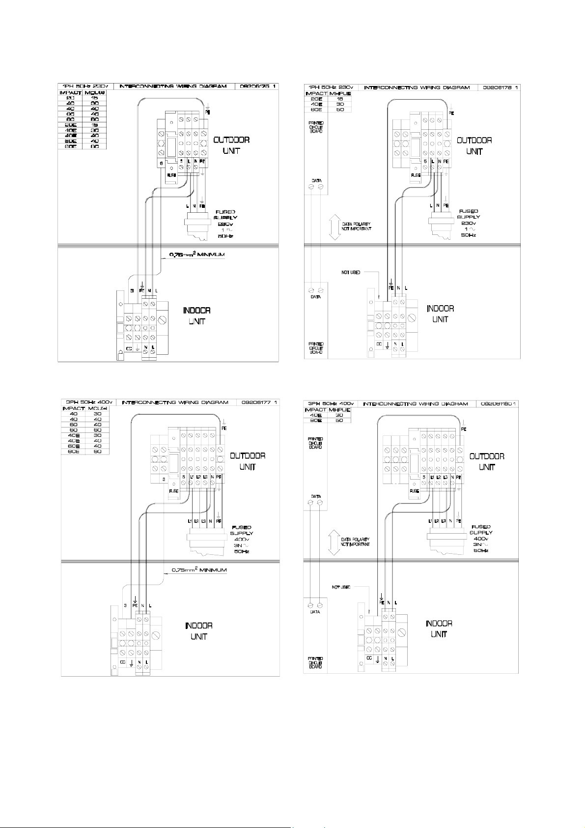
INTERCONNECTING WIRING DIAGRAMS
20(E) - 60(E) + 1 Phase MCU+ 15 – 60 20E - 60E + 1 Phase MHPUE 15 - 50
40(E) - 60(E) + 3 Phase MCU(+) 30 - 60 40E - 60E + 3 Phase MHPUE 30 - 50
17/20
53799173-05
Page 18
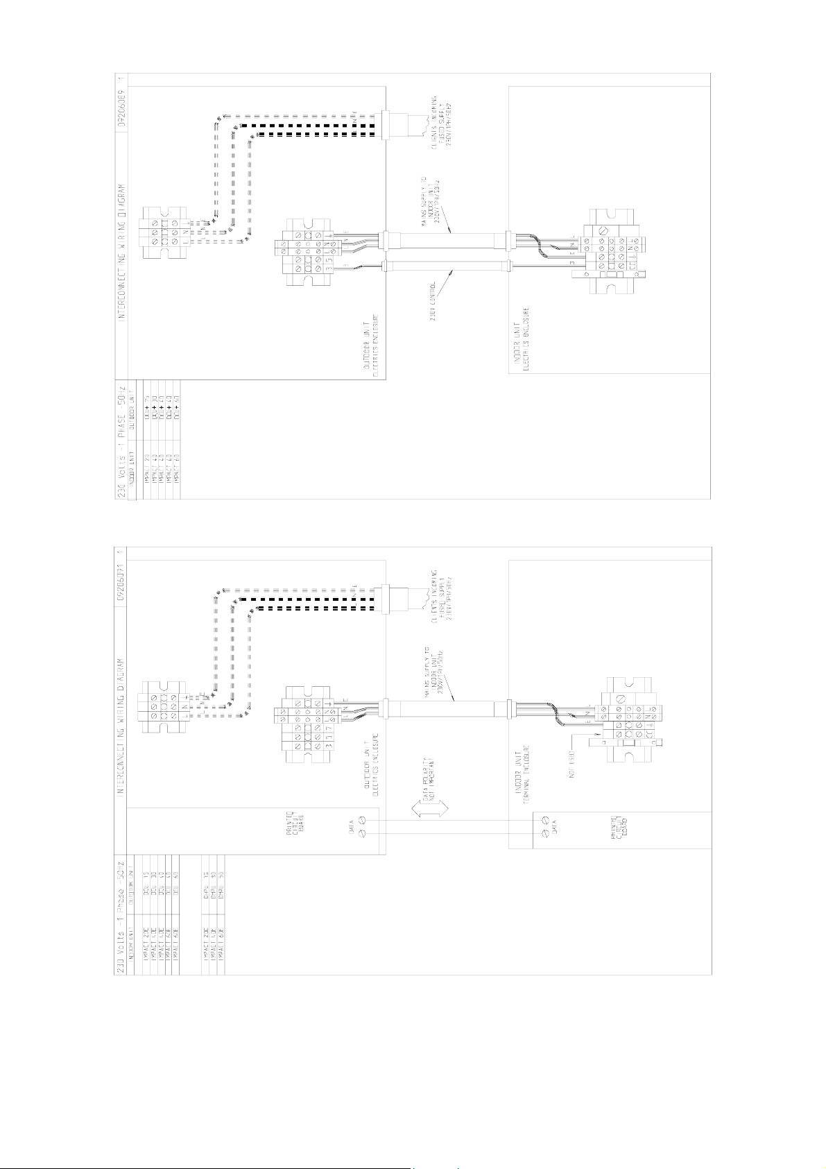
IMPACT 20 –60 and 1 PHASE DCU+ 15 – 60
Heronhill - for all your Marstair requirements
Tel: 01823 665660
www.heronhill.co.uk
Fax: 01823 665807
IMPACT 20E – 60E and 1 PHASE DCU+/DHPUE 15 - 60
+
+
+
+
+
+
+
+
18/20
53799173-05
Page 19
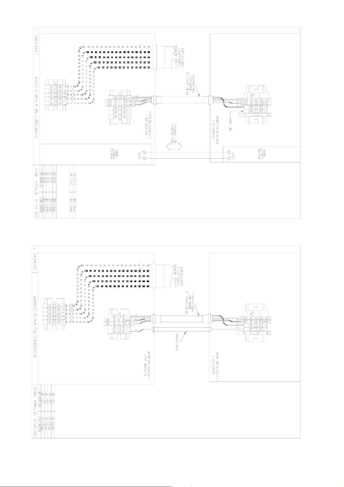
IMPACT 40 - 60 and 3 Phase DCU+ 30 - 60
Heronhill - for all your Marstair requirements
Tel: 01823 665660
www.heronhill.co.uk
Fax: 01823 665807
IMPACT 40E - 60E and 3 Phase DCU+/DHPUE 30 – 60
++
++
19/20
53799173-05
Page 20
Heronhill - for all your Marstair requirements
Tel: 01823 665660
www.heronhill.co.uk
Fax: 01823 665807
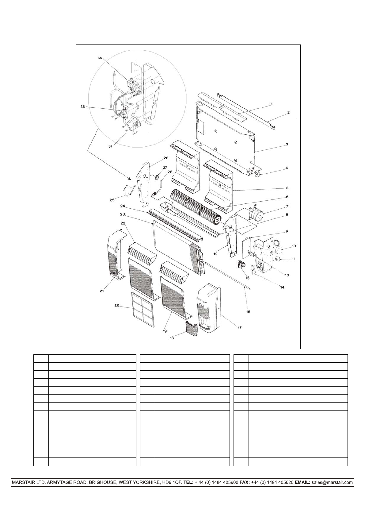
EXPLODED DIAGRAM OF IMPACT WITH COMPONENT IDENTIFICATION (IMPACT 40
SHOWN)
1
Top cover plate
2
Wall mounting bracket
3
Back panel
4
De-ice thermostat
5
Polystyrene scroll
6
Impeller
7
Motor
8
Drip tray assembly
9
Power board (electronic)
10
Thermostat (e/mechanical)
11
Rotary switch (electromechanical)
12
Right hand coil bracket
13
Receiver board (electronic)
14
Rotary knob (Electromechanical)
15
Terminal assembly
16
Heater element
17
Right hand end cover
18
Right hand door cover
19
Front cover
20
Filter
21
Left hand end cover
22
Top box assembly
23
Coil and header
24
Extrusion
25
Drip deflector Remote controller (not shown) shown)
26
Left hand coil bracket 2 Amp fuse (not shown)
27
Rubber housing Heater relay (not shown)
28
Impeller spring
20/20
29
Heater cut-out assembly
30
Electrics plate
31
Capacitor
32
Blank cover (electromechanical)
33
LED cover (electronic)
34
De-Ice sensor (electronic)
35
Return air sensor (electronic)
36
Condensate pump
37
Condensate pump sensor
38
Condensate pump PCB
53799173-05
 Loading...