

Page 1
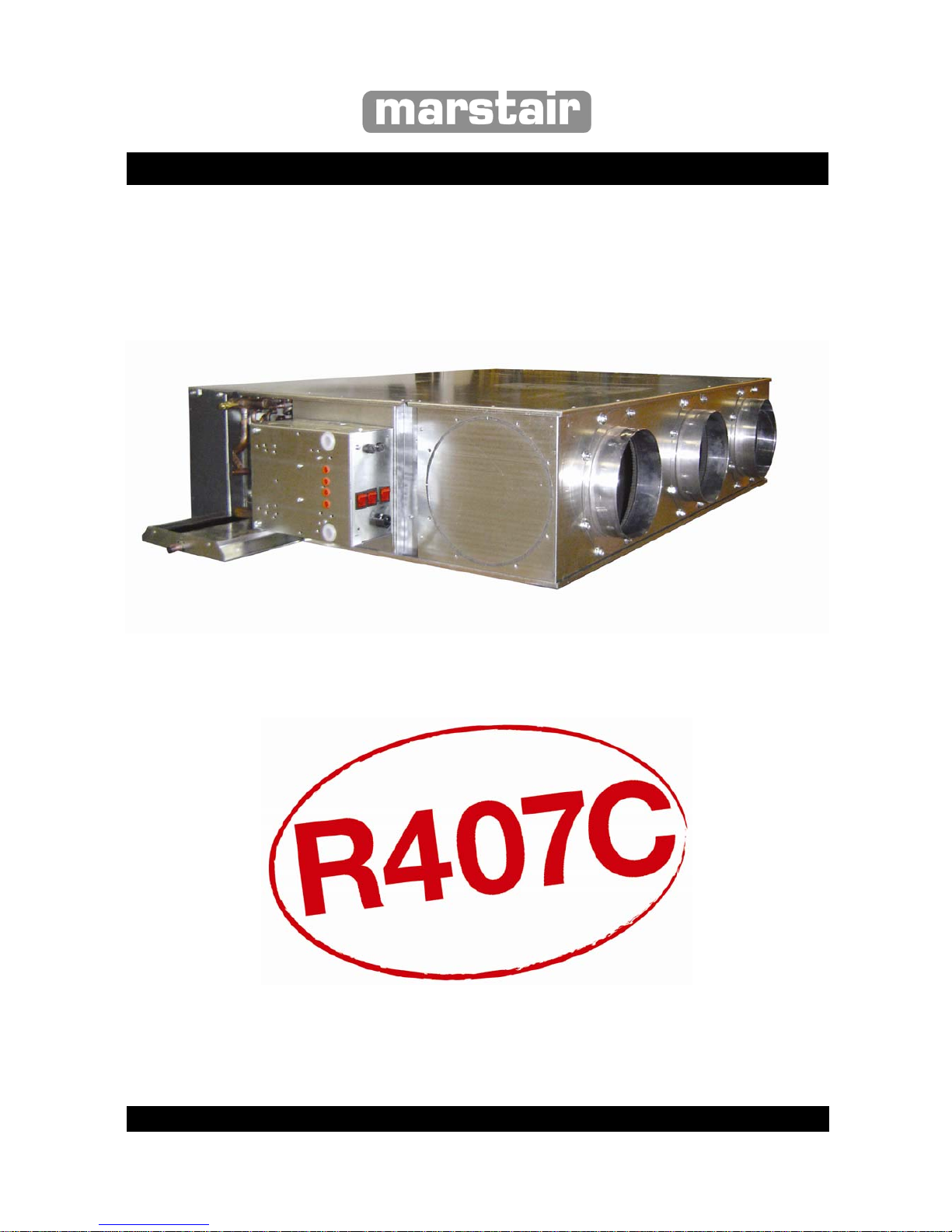
INSTALLATION INSTRUCTION
566 SERIES DXD/H FAN COIL UNITS
56608008-03
Heronhill - for all your Marstairs requirements
Tel: 01823 665660
www.heronhill.co.uk
Fax: 01823 665807
Page 2

GENERAL
56608008-03
1. TEV Ltd recommend that personnel working on this equipment be skilled and fully conversant with
the appropriate Air Conditioning, Refrigeration and Electrical practices and have sound knowledge
of current Industrial Safe Working practices.
2. These units are supplied with a holding charge of oxygen free nitrogen and polyolester oil.
Do not open the valves until the system is fully installed.
Do not mix oils and refrigerants.
3. These units contain live electrical components, moving parts and refrigerant under pressure.
Always site out of reach of children and protect from vandalism.
4. The data plate only gives information for the indoor unit. For system details add input power and
current of indoor and outdoor unit, including any heater load.
5. FUSES- for recommended fuse size see indoor unit instructions.
Heronhill - for all your Marstairs requirements
Tel: 01823 665660
www.heronhill.co.uk
Fax: 01823 665807
Page 3

LOCKNUTS
SCREWED
ROD
WASHERS
HANGING LUG DETAIL
DXD/H SPR FAN COIL UNIT INSTALLATION
DXD/H fan coil units are designed to be installed within a ceiling void. Air discharge should be via insulated ducting,
connected to 250mm diameter spigots (200mm diameter spigots also available) and to appropriately sized discharge
plenums/grilles. Ducting and discharge facilities are supplied by others and are not included with the fan coil units.
Similarly, return air arrangements, via ducting or to the ceiling void, must also be provided.
The installer must ensure that the mounting suspension points are capable of supporting the operating weight of the unit,
(refer to the table below).
UNIT FIXING
1. Before lifting the unit into position, mark out the four outer fixing points as shown below, and fit suspension rods of
appropriate length and diameter, (minimum recommended thread size M8). Two inner, central fixing points are
available for installer convenience. DO NOT lift the unit by its spigots, drain tray or electrics box when raising it
into position.
2. Lift the unit into position and secure with appropriate fixings (as shown).
The use of lock nuts will stabilize the unit.
NOTE: The drain tray is designed with a natural fall to ensure complete
drainage. It is essential, for the correct operation of the condensate
removal system, that the unit is square and level.
Heronhill - for all your Marstairs requirements
Tel: 01823 665660
www.heronhill.co.uk
Fax: 01823 665807
Page 4
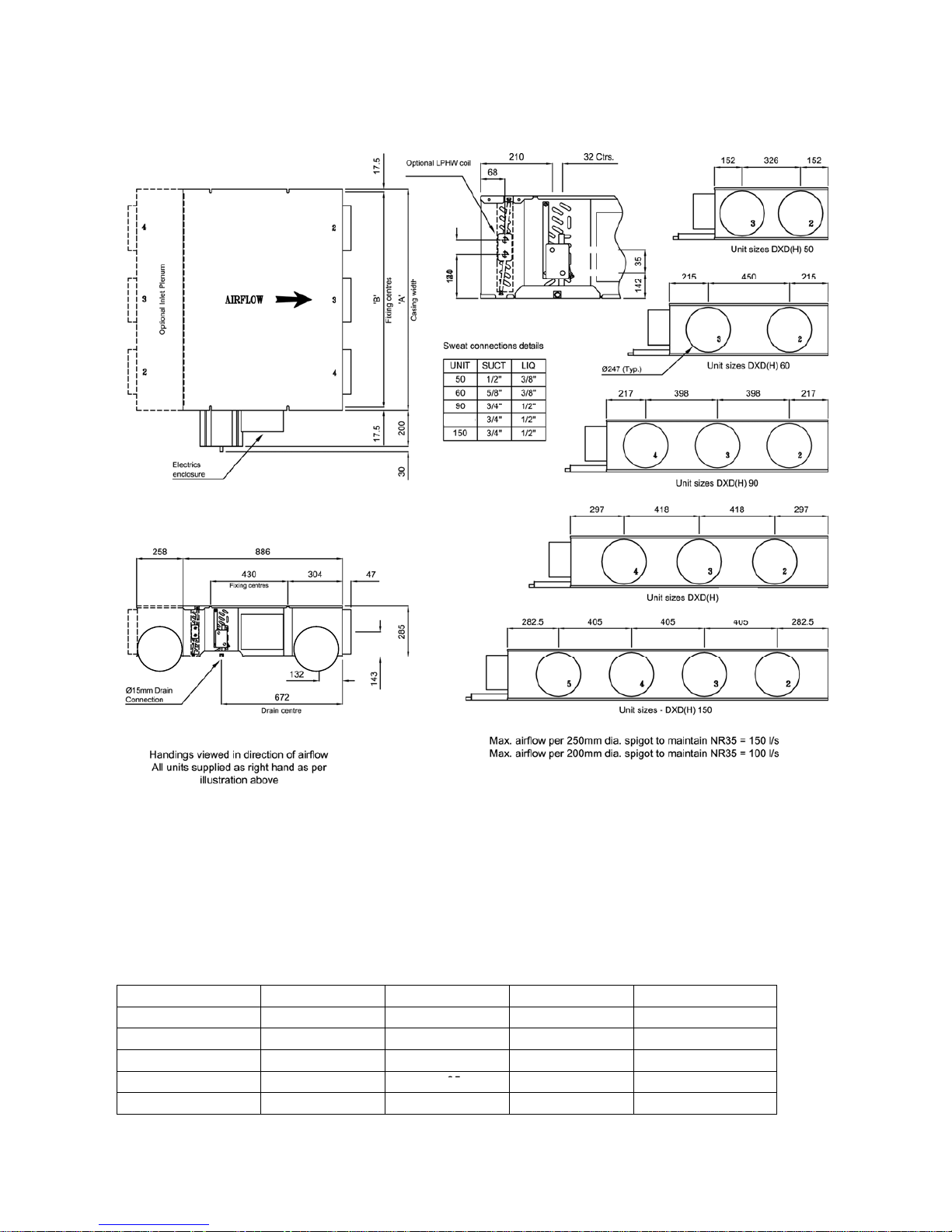
UNIT DIMENSIONS
1. All front spigots must be used.
2. A maximum of 30pa resistance is allowed (total of inlet and discharge added together).
DIMENSIONAL INFORMATION
UNIT MODEL Dim ‘A’ Dim ‘B’ SPIGOTS WEIGHT
(Approx Kg)
DXD(H) 50 630 595 2-3 42
DXD(H) 60 880 845 2-3 52
DXD(H) 90 1230 1195 2-3-4 69
DXD(H) 130 1430 1395 2-3-4 86
DXD(H) 150 1780 1745 2-3-4-5 103
130
130
Heronhill - for all your Marstairs requirements
Tel: 01823 665660
www.heronhill.co.uk
Fax: 01823 665807
Page 5
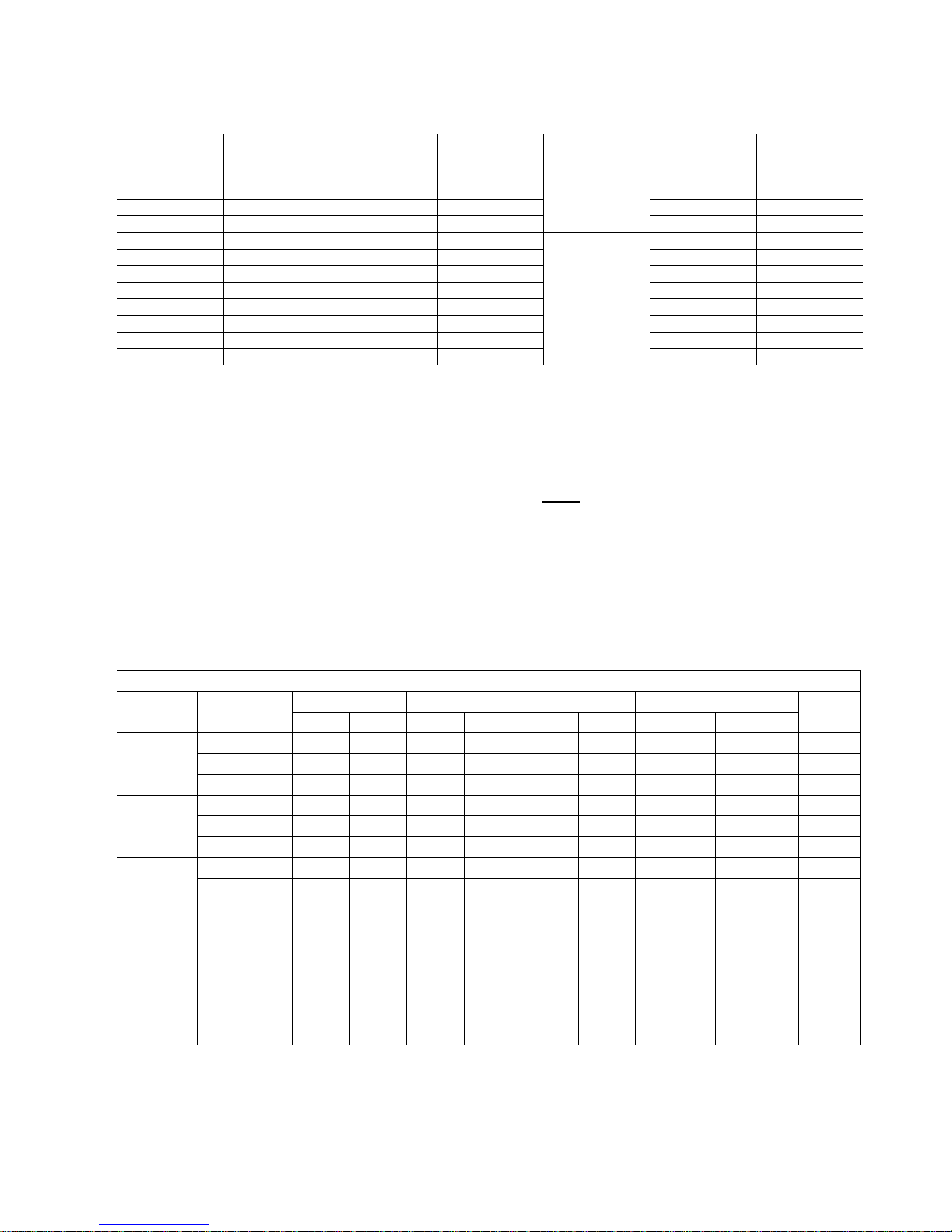
RESTRICTOR & EXPANSION DEVICES
* Restrictor change required - supplied loose in outdoor unit
** Heating expansion assembly - supplied loose in the indoor unit.
ELECTRICAL CONNECTIONS, CONTROLS and DATA
Mains, control and interconnecting cables must be supplied and fitted by the installer. Installer wiring must be carried out
in accordance with local and national codes. Cables must be size compatible with the recommended fuse for a given
system. An isolator switch should be positioned within easy reach of the unit.
If slave units are connected to a standard unit, isolation of any slave MUST
also isolate the standard unit.
The equipment MUST be earthed. Installers must supply a method of securing any solid sheathed cable.
DXD/H UNIT WIRING
Remove the electrics box cover (2 screws) and connect a suitably fused and isolated mains supply.
Site fitted controls should be connected as specified on the wiring diagram found on the inside face of the electric box
cover: typical wiring diagrams are shown on pages 5 and 6, but these are for reference only as many CWD units have a
unique configuration
ELECTRICAL DATA AND N.R.GUIDE
ELECTRICAL DATA
Input (watts) FLC (Amps) S.C. (Amps) Specific Fan Power
MODEL SPD
A’flow
(l/s)
AC EC/DC AC EC/DC AC EC/DC AC EC/DC
N.R.
GUIDE
1 160 93 53 0.57 0.46 1.71 1.38 0.58 0.33 35
2 170 98 62 0.59 0.53 1.77 1.59 0.58 0.36 37
DXD(H) 50
3 180 118 71 0.65 0.60 1.95 1.80 0.66 0.40 40
1 180 125 63 0.65 0.60 1.95 1.80 0.69 0.35 35
2 210 146 - 0.74 - 2.22 - 0.70 - 37
DXD(H) 60
3 225 177 - 0.80 - 2.40 - 0.79 - 40
1 310 196 83 1.18 0.80 3.54 2.40 0.63 0.27 35
2 360 236 112 1.30 1.13 3.90 3.39 0.66 0.31 37
DXD(H) 90
3 435 262 - 1.38 - 4.14 - 0.60 - 40
1 335 218 103 1.55 0.71 4.65 2.13 0.65 0.31 35
2 382 264 130 1.71 0.86 5.13 2.58 0.69 0.34 37
DXD(H) 130
3 462 294 184 1.77 1.21 5.31 3.63 0.64 0.40 40
1 425 290 140 2.08 0.91 6.24 2.73 0.68 0.33 35
2 477 330 179 2.20 1.06 6.60 3.18 0.69 0.38 37
DXD(H) 150
3 560 373 259 2.32 1.40 6.96 4.20 0.67 0.46 40
DXD DXDH MRC+ MHPUE
EXPANSION
ASSY
COOLING
RESTRICTOR
HEATING
RESTRICTOR
50 - 30 - 0.040 -
50 - 30 0.040 0.039
60 - 60 - 0.051 -
60 - 60
3/8”
0.055 0.053
90 - 90 0.063 -
- 90 - 90 0.067 0.058/
130 - 100 - 0.068 -
- 130 - 100 0.068 0.086**
130 - 130 - 0.071 -
- 130 - 130 0.076 0.086**
150 - 130 - 0.074* -
- 150 - 130
1/2”
0.080* 0.092**
Heronhill - for all your Marstairs requirements
Tel: 01823 665660
www.heronhill.co.uk
Fax: 01823 665807
Page 6
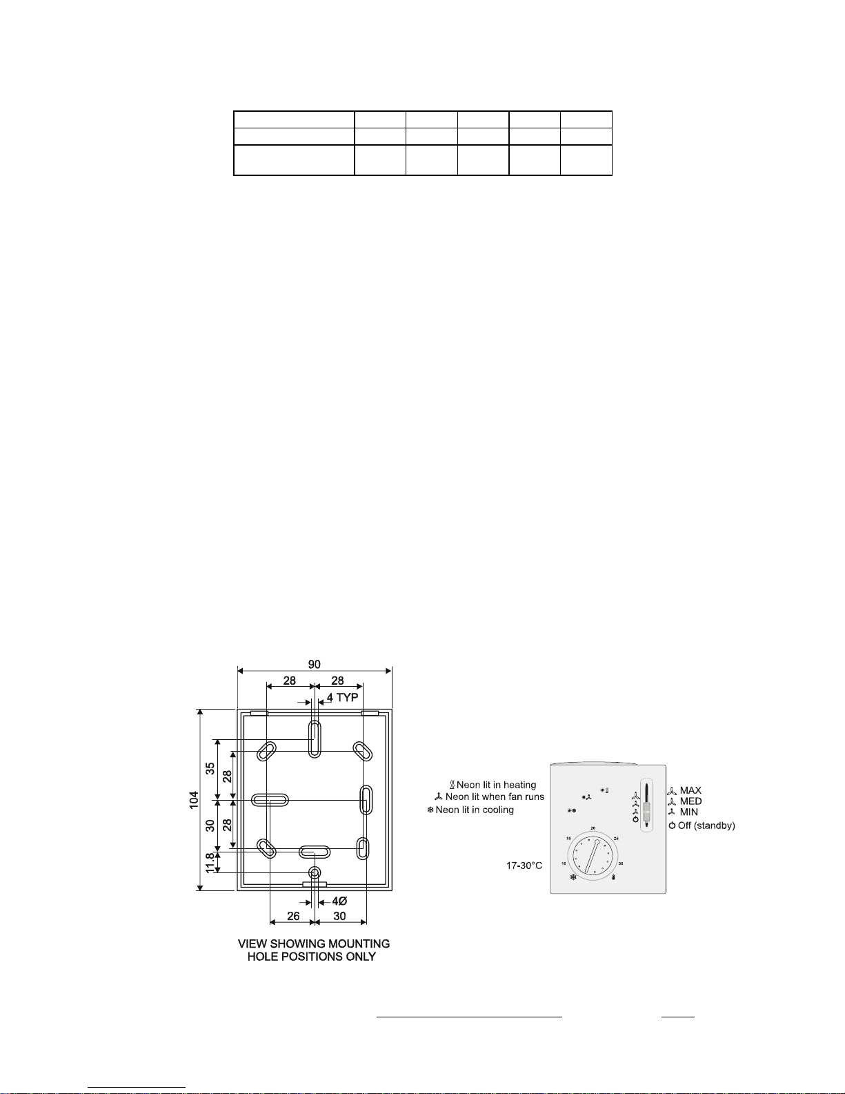
RECOMMENDED FUSE SIZES (Amps)
Model 50 60 90 130 150
STANDARD
5 5 10 10 10
STANDARD +
Electric Heating
16 16 16 20 20
DUCTWORK
Connect discharge ductwork to the spigots provided. Spigot positions are shown below. Spigots are designed to accept
250mm diameter ducting (200mm diameter spigots are available as an option).
The installation engineer must ensure that insulated ducting is used and that the complete spigot exterior is insulated up to
the unit casing to prevent condensation forming.
INSTALLATION OF A REMOTE CONTROLLER
Select a position to mount the thermostat taking into account the following comments:
a. The thermostat must be mounted on a flat surface within the area conditioned by the unit to which it is
connected.
b. Avoid draughts, heat from radiators, temperature variations from hot/cold water pipes and direct sunlight.
c. Avoid corners of the room where air is likely to stagnate.
d. Avoid direct air discharge from the unit onto the thermostat.
e. Avoid positions where the thermostat may be covered or obscured.
f. If the room contains pillars, mount on the side of the pillar furthest away from the unit.
If thermostat 97200211 (RCC 30) is used:-
The thermostat should be wired with 7 core double insulated cable, 0.5mm2 minimum, preferably in plastic conduit for
good appearance.
Using a flat-bladed screwdriver in the slot at the bottom of the casing lever off the cover.
Mount the backpanel directly to a wall or onto a plinth, using the fasteners supplied.
Wire between the remote controller and the unit as shown on the unit wiring diagram
: the table below is typical only:
*Optional return air sensor 97200212 can detect return air temperature at the unit rather than the controller.
Heronhill - for all your Marstairs requirements
Tel: 01823 665660
www.heronhill.co.uk
Fax: 01823 665807
Page 7
DIP switches at the bottom rear of the controller can be set on site to suit the application.
DIP switch
Function
ON position
OFF position
1
Fan control
Fan control is temperature dependent in all
operating modes
Fan control in normal operation is
temperature independent
2
Operating mode changeover
via external switch
Changeover between normal operation
and energy saving mode
Changeover between normal operation
and standby
3
Action of switch for externally
operated mode changeover
Changeover activated when contact of
switch is closed
Changeover activated when contact of
switch is open
4
Standby
Frost protection disabled
Frost protection enabled
5
Switching differential
1K in heating mode, 0.5K in cooling mode
4K in heating mode, 2K in cooling mode
6
Dead zone in normal operation 2K
5K
=
WHEN INSTALLATION HAS BEEN COMPLETED - CHECK:-
1. All pipework and joints for leaks
2. That all pipes and fittings are insulated
3. That terminals are tight and that no wire cores are exposed
4. That duct connections are air tight and insulated where necessary.
5. Filters are clean and undamaged
MAINTENANCE
A. Every 2 months
Inspect the filters and clean or replace as necessary
B. Every 6 months
Inspect and clean the fan rotors.
C. Every 12 months
1. Check the unit fixing
2. Ensure that the fan motor and fan deck fixings are tight.
3. Check the unit wiring for damage and ensure that all terminals are tight.
TEV Ltd.
Armytage Road, Brighouse,
West Yorkshire, HD6 1QF, UK.
Heronhill - for all your Marstairs requirements
Tel: 01823 665660
www.heronhill.co.uk
Fax: 01823 665807
Page 8

Tel: +44 (0) 1484 405630.
Fax: +44 (0) 1484 405620.
Email: [email protected]
Heronhill - for all your Marstairs requirements
Tel: 01823 665660
www.heronhill.co.uk
Fax: 01823 665807
 Loading...