


55208033-08
TECHNICAL MANUAL
DX CASSETTE 600E/M, 600E & 600L
Heronhill - for all your Marstair requirements
Tel: 01823 665660
www.heronhill.co.uk
Fax: 018123 665807

2/25
55208033-08
INDEX
CONTENTS
PAGE
General. 2
Unit part numbers, dimensions & weights. 3
Features, optional accessories & system matches 4
Performance data. 5
Airflows & discharge velocities. 6
Sound power & sound pressure levels. 6
Branch duct (spigot) data. 7
Electrical data: Loads & fuses 8-9
Installation.
10
Contents & dimensions. 10
Removal of chassis & mounting. 11
Pipework & restrictor sizes. 12
Remote controllers. 13-14
Fan speed selection & interconnecting wiring diagrams. 15-17
Reinstalling chassis & fascia. 18
Condensate drain piping. 19
User maintenace. 21
Fault finding. 22-23
Component identification. 24-25
GENERAL
1. TEV Ltd recommend that personnel working on this equipment be skilled and fully conversant with
the appropriate Air Conditioning, Refrigeration and Electrical practices and have sound knowledge
of current Industrial Safe Working practices.
2. These units consist of 600E/M cassettes using remote wired controllers, 600 L cassettes using
infrared controllers and 600 E cassettes using infrared controllers.
3. These units contain live electrical components, moving parts and refrigerant under pressure.
Always site out of reach of children and protect from vandalism.
4. The data plate only gives information for the 600 unit.
5. Refer to the outdoor unit manual / installation instructions for evacuating and adding refrigerant.
Heronhill - for all your Marstair requirements
Tel: 01823 665660
www.heronhill.co.uk
Fax: 018123 665807

3/25
55208033-08
PART NUMBERS
Fascia
55222000 (all models)
Fitted with 0.5m lift pump
Fitted with 5m condensate pump
600E/M model 20 40 60
20 40 60
Part number
55222001 55222002 55222003
55222004 55222005 55222006
600L model 20L 40L 60L
20L 40L 60L
part number
55222007 55222008 55222009
55222022 55222023 55222024
600E model 20E 40E 60E
20E 40E 60E
Part number
55222013 55222014 55222015
55222016 55222017 55222018
NOTE: The fascia is shipped separate from the chassis and they are ordered on separate part numbers.
DIMENSIONS AND WEIGHTS
UNPACKED (with fascia fiitted).
600
Model
20 40 60
Height mm
335 335 335
Width mm
675 675 675
Depth mm
675 675 675
Weight kg
21 23 25
PACKED
600 Chassis
600 Fascia
Model
20 40 60
20 / 40 / 60
Height mm
360 360 360 100
Width mm
810 810 810 760
Depth mm
610 610 610 760
Weight kg
22 24 26 4
Heronhill - for all your Marstair requirements
Tel: 01823 665660
www.heronhill.co.uk
Fax: 018123 665807

4/25
55208033-08
FEATURES AND OPTIONAL ACCESSORIES
STANDARD
600E/M 600L 600E
De-ice thermostat/sensor STD STD STD
3 fan speed combinations STD STD STD
Remote infrared control --- STD STD
Remote hard wired control STD --- STD
0.5m lift pump STD STD STD
5m condensate pump STD STD STD
Programmable timer --- STD STD
Long life cleanable filter STD STD STD
Remote temperature sensor STD --- ---
OPTIONS
NOTE: These kits are easier to fit before installation, some may also be factory fitted.
SYSTEM MATCHES
Air Conditioning Systems
Heat Pump Systems
600 (ALL)
MCU+ or DCU+
600L / 600E MHPUL / MHPUE / DHPUE
20 15 20 15
20 20 40 30
20 30 60 50
40 30
40 40
40 50
60 40
60 50
60 60
NOTE: Table above is for 600 units matched with Marstair outdoor units.
Heronhill - for all your Marstair requirements
Tel: 01823 665660
www.heronhill.co.uk
Fax: 018123 665807

5/25
55208033-08
PERFORMANCE DATA (kW)
NOTE THAT THERE ARE 3 SPEED RANGES OF LOW, MEDIUM AND HIGH
Range 3 = highest for maxium duties
Range 2 = medium for normal operations
Range 1 = lowest for minimum noise levels
UK CONDITIONS
ROOM 21°C/15°C
AMBIENT 27°C/19°C
EUROVENT
(NEMA)
ROOM
27°C/19°C
AMB 35°C/24°C
TROPICAL
ROOM
29°C/19°C
AMB 46°C/24°C
RANGE 3
LOW MEDIUM HIGH HIGH HIGH
RANGE 2
LOW MEDIUM HIGH
RANGE 1 LOW MEDIUM HIGH
600
(ALL)
MCU+
or
DCU+
TOT SHR SENS TOT SHR SENS TOT SHR SENS TOT SHR SENS TOT SHR SENS TOT SHR SENS TOT SHR SENS
20 15 1.77 0.75 1.33 1.82 0.80 1.46 1.87 0.85 1.59 1.91 0.92 1.75 1.94 1.00 1.94 2.13 1.00 2.13 2.05 1.00 2.05
20 20 2.28 0.69 1.58 2.35 0.72 1.70 2.40 0.76 1.83 2.45 0.81 1.99 2.50 0.88 2.19 2.65 0.93 2.47 2.28 1.00 2.28
20 30 N/A* 2.63 0.70 1.84 2.71 0.73 1.97 2.78 0.77 2.14 2.85 0.83 2.35 3.03 0.86 2.61 2.37 1.00 2.37
40 30 3.13 0.67 2.09 3.29 0.68 2.25 3.40 0.71 2.41 3.52 0.74 2.61 3.60 0.79 2.84 3.86 0.81 3.14 3.06 1.00 3.06
40 40 3.50 0.66 2.30 3.69 0.67 2.47 3.84 0.69 2.63 3.98 0.71 2.83 4.09 0.75 3.06 4.27 0.77 3.30 3.84 0.93 3.57
40 50 N/A* 4.59 0.66 3.01 4.83 0.67 3.22 5.05 0.69 3.47 5.27 0.72 3.78 5.66 0.72 4.08 4.73 0.89 4.20
60 40 3.60 0.66 2.39 3.79 0.68 2.58 3.92 0.70 2.76 4.06 0.73 2.98 4.18 0.78 3.25 4.33 0.81 3.52 3.87 0.99 3.84
60 50 4.35 0.65 2.82 4.66 0.66 3.06 4.89 0.67 3.26 5.14 0.68 3.51 5.35 0.71 3.81 5.72 0.72 4.09 4.80 0.88 4.20
60 60 N/A* 4.97 0.65 3.24 5.24 0.66 3.45 5.51 0.67 3.71 5.78 0.70 4.02 6.26 0.69 4.32 5.18 0.84 4.36
* Cannot be used on low speed
Rated at BS2852: Part 1: 1982: UK condition C; NEMA condition A; Tropical condition B
HEAT PUMP
a. Cooling (MAX speed outdoor unit fan)
UK CONDITIONS
ROOM 21°C/15°C
AMBIENT 27°C/19°C
EUROVENT (NEMA)
ROOM 27°C/19°C
AMBIENT 35°C/24°C
RANGE 3
LOW MEDIUM HIGH HIGH
RANGE 2
LOW MEDIUM HIGH
RANGE 1 LOW MEDIUM HIGH
600 (ALL)
MHPUL
MHPUE
DHPUE
TOT SHR SENS TOT SHR SENS TOT SHR SENS TOT SHR SENS TOTAL SHR SENS TOTAL SHR SENS
20 15 1.77 0.75 1.33 1.82 0.80 1.46 1.870.85 1.59 1.91 0.92 1.75 1.94 1.00 1.94 2.23 1.00 2.23
40 30 3.13 0.67 2.09 3.29 0.68 2.25 3.400.71 2.41 3.52 0.74 2.61 3.60 0.79 2.84 3.86 0.81 3.14
60 50 4.35 0.65 2.82 4.66 0.66 3.06 4.890.67 3.26 5.14 0.68 3.51 5.35 0.71 3.81 5.72 0.72 4.09
b. Heating (Room 20°C/12°C, outdoor unit fan at MAX speed)
HEATING OUTPUT AT 7°C AMBIENT
(EUROVENT)
HEATING OUTPUT AT -1°C AMBIENT
RANGE 3 LOW MEDIUM HIGH LOW MEDIUM HIGH
RANGE 2 MEDIUM HIGH MEDIUM HIGH
RANGE 1 HIGH HIGH
600 (ALL)
MHPUL
MHPUE
DHPUE
kW COP kW COP kW COP kW COP kW COP kW COP
20 15 2.06 2.50 2.07 2.52 2.13 2.60 1.58 2.10 1.68 2.20 1.72 2.23
40 30 2.92 2.70 2.98 2.75 3.46 3.23 2.30 2.30 2.40 2.40 2.60 2.60
60 50 5.48 2.48 5.68 2.58 5.71 2.89 4.42 2.31 4.64 2.31 4.75 2.59
Heronhill - for all your Marstair requirements
Tel: 01823 665660
www.heronhill.co.uk
Fax: 018123 665807

6/25
55208033-08
AIRFLOWS
RANGE 3
LOW SPEED MEDIUM SPEED HIGH SPEED
RANGE 2
LOW SPEED MEDIUM SPEED HIGH SPEED
RANGE 1 LOW SPEED MEDIUM SPEED HIGH SPEED
600 (ALL) m3/s m3/s m3/s m3/s m3/s
20 0.12 0.146 0.173 0.209 0.256
40 0.12 0.146 0.173 0.209 0.256
60 0.12 0.146 0.173 0.209 0.256
DISCHARGE VELOCITIES
SOUND POWER and SOUND PRESSURE
speed 1 = lowest, speed 5 = highest
SOUND POWER LEVELS
Frequency Hz
SOUND PRESSURE LEVELS
600 (ALL) SPEED 125 250 500 1K 2K 4K dBA
dBA NC
1 56.3 48.3 45.5 39.0 36.6 35.8 47 26 18
2 58.8 51.9 50.2 44.9 41.4 37.5 52 31 23
3 61.6 57.8 55.6 53.8 48.5 44.4 58 37 31
4 62.9 60.1 57.6 56.3 51.3 46.8 61 40 34
20
5 67.0 65.6 62.9 61.3 57.6 53.0 66 45 39
1 55.7 49.7 46.4 39.2 37.2 35.7 48 27 19
2 57.5 53.6 50.9 45.1 42.3 39.8 52 31 24
3 61.9 59.0 56.2 54.2 48.9 44.2 59 38 32
4 63.1 62.0 58.3 56.6 51.6 46.7 61 40 34
40
5 68.0 67.3 63.5 61.9 57.5 52.8 67 46 40
1 55.5 51.1 47.8 41.8 41.1 40.0 50 29 22
2 58.8 54.8 52.0 47.5 46.2 42.3 54 33 26
3 62.1 59.2 56.4 53.6 49.9 43.2 59 38 31
4 64.1 61.2 58.5 55.6 51.7 45.4 60 39 33
60
5 69.4 66.5 63.1 60.6 56.5 51.6 66 45 39
Sound Power Levels were obtained in conformance with BS 4196: Part 5: 1981. Values are shown in dB with a standard reference of 1 pW.
Sound Pressure Levels are dB relative to 2 x 10
-5
N/m2 and are calculated from results measured in anechoic conditions. Values relate to a
position of 3m away from the centre line of the unit, 1m down.
Heronhill - for all your Marstair requirements
Tel: 01823 665660
www.heronhill.co.uk
Fax: 018123 665807

7/25
55208033-08
BRANCH DUCT
The graphs below show the amount of conditioned air passed by a single branch duct.
FAN SPEED RANGE 1 FOR MINIMUM NOISE LEVELS
As shown on the graphs above, branch duct airflow can be be increased by blanking off the fascia side to
which the branch duct has been connected.
FAN SPEED RANGE 2 FOR NORMAL NOISE LEVELS
FAN SPEED RANGE 3 FOR MAXIMUM NOISE LEVELS
Heronhill - for all your Marstair requirements
Tel: 01823 665660
www.heronhill.co.uk
Fax: 018123 665807

8/25
55208033-08
ELECTRICAL DATA
Cooling data rated at EUROVENT (NEMA) conditions 27°C / 19.4°C indoor; 35°/24°C ambient.
Heating data rated at 20°C/12°C indoor; 7°C/6°C ambient
With MCU+
1 Ph 230V 50Hz 3 Ph 400V 50Hz
MODEL
COMBINATION
INPUT
FULL LOAD
AMPS
SYSTEM
MAX.
STARTING
CURRENT
INPUT
FULL LOAD
AMPS
SYSTEM
MAX.
STARTING
CURRENT
Cooling Heating Cooling Heating Cooling Heating Cooling Heating
600 (ALL) MCU+ kW kW AMPS AMPS AMPS kW kW A/PH A/PH* A/PH
20 15 1.2 2.0 6.4 8.3 23 -- -- -- -- -20 20 1.4 2.0 7.4 8.3 28 -- -- -- -- -20 30 1.7 2.0 8.6 8.3 37 1.7 2.0 4.1 8.3 19
40 30 1.7 2.0 8.6 8.3 37 1.7 2.0 4.1 8.3 19
40 40 2.2 2.0 10.7 8.3 51 2.1 2.0 5.3 8.3 23
40 50 2.1 2.0 9.4 8.3 59 2.0 2.0 4.7 8.3 27
60 40 2.2 2.0 10.7 8.3 51 2.1 2.0 5.3 8.3 23
60 50 2.1 2.0 9.4 8.3 59 2.0 2.0 4.7 8.3 27
60 60 2.5 2.0 10.5 8.3 63 2.4 2.0 4.7 8.3 33
With DCU+
1 Ph 230V 50Hz 3 Ph 400V 50Hz
MODEL
COMBINATION
INPUT
FULL LOAD
AMPS
SYSTEM
MAX.
STARTING
CURRENT
INPUT
FULL LOAD
AMPS
SYSTEM
MAX.
STARTING
CURRENT
Cooling Heating Cooling Heating
Cooling Heating Cooling Heating
600 (ALL) DCU+ kW kW AMPS AMPS AMPS kW kW A/PH A/PH* A/PH
20 15 1.4 2.0 6.6 8.3 25 -- -- -- -- --
20 20 1.5 2.0 7.4 8.3 29 -- -- -- -- --
20 30 1.8 2.0 9.0 8.3 37 1.9 2.0 4.1 8.3 19
40 30 1.9 2.0 9.0 8.3 37 1.9 2.0 4.1 8.3 19
40 40 2.4 2.0 11.3 8.3 51 2.4 2.0 5.2 8.3 24
40 50 3.0 2.0 11.8 8.3 52 2.5 2.0 5.0 8.3 23
60 40 2.4 2.0 11.3 8.3 51 2.4 2.0 5.2 8.3 24
60 50 3.0 2.0 11.8 8.3 52 2.5 2.0 5.0 8.3 23
60 60 3.2 2.0 15.1 8.3 61 3.2 2.0 6.4 8.3 26
With MHPUL/MHPUE
1 Ph 230V 50Hz 3 Ph 400V 50Hz
INPUT FULL LOAD AMPS INPUT FULL LOAD AMPS
MODEL
COMBINATION
STD.
MODEL
+ELECT
Heating
STD.
MODEL
+ELECT
Heating
SYSTEM
MAX.
STARTING
CURRENT
STD.
MODEL
+ELECT
Heating
STD.
MODEL
+ELECT
Heating
SYSTEM
MAX.
STARTING
CURRENT
600L / E MHPUL/E kW kW AMPS AMPS AMPS kW kW A/PH A/PH* A/PH
20 15 1.2 3.1 6.4 14.7 24 -- -- -- -- --
40 30 1.7 3.4 8.6 16.4 44 1.7 3.5 4.1 12.2 27
60 50 2.1 4.1 9.4 17.2 67 2.0 3.8 4.7 12.3 35
With DHPUE
1 Ph 230V 50Hz 3 Ph 400V 50Hz
INPUT FULL LOAD AMPS INPUT FULL LOAD AMPS
MODEL
COMBINATION
STD.
MODEL
+ELECT
Heating
STD.
MODEL
+ELECT
Heating
SYSTEM
MAX.
STARTING
CURRENT
STD.
MODEL
+ ELECT
Heating
STD.
MODEL
+ ELECT
Heating
SYSTEM
MAX.
STARTING
CURRENT
600E DHPUE kW kW AMP S AMPS AMPS kW kW A/PH A/PH* A/PH
20 15 1.4 3.3 4.9 12.9 24 -- -- -- -- --
40 30 1.8 3.7 8.9 16.9 45 1.8 3.7 4.1 12.1 27
60 50 2.5 4.4 11.8 19.8 59 2.5 4.3 5.4 13.2 32
Heronhill - for all your Marstair requirements
Tel: 01823 665660
www.heronhill.co.uk
Fax: 018123 665807

9/25
55208033-08
ELECTRICAL LOADS [ 230V 50Hz 1Ph (A) OR 400V 50Hz 3PhN (A/Ph)]
600 (ALL)
20 40 60
FAN MOTOR
0.5 0.5 0.5
LIFT PUMP (10 watts)
9mA 9mA 9mA
CONDENSATE PUMP (27.6 watts)
12.5mA 12.5mA 12.5mA
ELECTRIC HEATER (1kW) 4.2 4.2 4.2
ELECTRIC HEATER (2Kw) 8.3 8.3 8.3
FUSES
The system and its supply/interconnecting wiring must be protected by fuses, preferably High Rupture
Current (HRC) motor rated types (to BS EN60269) or miniature circuit breakers to (BS EN60898) or local
codes having similar time lag characteristics, that allow starting of the compressor yet still afford close
overcurrent protection under running conditions. The ratings below are for HRC motor rated fuses.
S= Standard units (no heaters) H= Electric heaters fitted
FUSES FOR ALL-ELECTRONIC SYSTEMS HAVING SEPARATE SUPPLIES
Provided that both indoor and outdoor units are electronic (ie. 600E matched with MHPUE or DHPUE) and
control cables between them are data cables, the units may be independently supplied and fused .
600
20E 40E 60E
1Ph Cool Only
5 5 5
1Ph with Electric Heating
10 10 10
FUSES FOR SYSTEMS WITH 1 PH
230V OUTDOOR UNITS (A)
600
20 40 60
MCU+
S H1 H2 S H1 H2 S H1 H2
15 16 16 16
20 16 16 16
30 16 16 16 16 16 16
40 20 20 20 20 20 20
50 16 16 16 16 16 16
60 20 20 20
DCU+ S H1 H2 S H1 H2 S H1 H2
15 16 16 16
20 16 16 16
30 16 16 16 16 16 16
40 20 20 20 20 20 20
50 25 25 25 25 25 25
60 25 25 25
MHPUE (L) S H1 H2 S H1 H2 S H1 H2
15 16 16 16
30 16 20 20
50 16 25 25
DHPUE S H1 H2 S H1 H2 S H1 H2
15 16 16 16
30 16 25 25
50 20 32 32
FUSES FOR SYSTEMS WITH 3PH
400V OUTDOOR UNITS (A/Ph)
600
20 40 60
MCU+
S H1 H2 S H1 H2 S H1 H2
30 10 10 10 10 10 10
40 10 10 10 10 10 10
50 10 10 10 10 10 10
60 10 10 10
DCU+ S H1 H2 S H1 H2 S H1 H2
30 10 10 10 10 10 10
40 10 10 10 10 10 10
50 10 10 10 10 10 10
60 16 16 16
MHPUE S H1 H2 S H1 H2 S H1 H2
30 10 16 16
50 10 16 16
DHPUE S H1 H2 S H1 H2 S H1 H2
30 10 16 16
50 10 20 20
MHPUL S H1 H2 S H1 H2 S H1 H2
30 10 16 16
50 10 16 16
Heronhill - for all your Marstair requirements
Tel: 01823 665660
www.heronhill.co.uk
Fax: 018123 665807

10/25
55208033-08
30
306
≥
580 x 580
610
300
675 x 675
187.5 187.5
INSTALLATION
CONTENTS
DIMENSIONS
Heronhill - for all your Marstair requirements
Tel: 01823 665660
www.heronhill.co.uk
Fax: 018123 665807

11/25
55208033-08
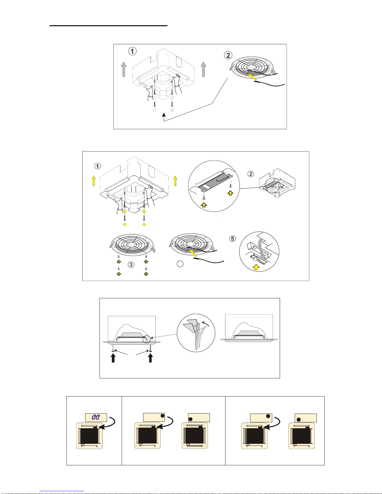
REMOVAL OF CHASSIS
600L & 600E
600E/M
MOUNTING
Heronhill - for all your Marstair requirements
Tel: 01823 665660
www.heronhill.co.uk
Fax: 018123 665807

12/25
55208033-08
PIPEWORK
HEATPUMP CONDITIONS
= NO RESTRICTOR CHANGE
NEEDED
Heat pump cooling conditions
MHPUE
IMAGE
600
COOLING
RESTRICTOR
FITTED
UK
CONDITIONS
NEMA
CONDITIONS
Heating
restrictor
fitted into the
expansion
assembly
15 20 033
035
30 40 040
039
50 60 052 051 051 041
Heat pump cooling conditions
DHPUE
IMAGE
600
COOLING
RESTRICTOR
FITTED
UK
CONDITIONS
NEMA
CONDITIONS
15 20 032
027
30 40 039
037
50 60 049
041
Heronhill - for all your Marstair requirements
Tel: 01823 665660
www.heronhill.co.uk
Fax: 018123 665807

13/25
55208033-08
REMOTE CONTROLLER
ON
Fan control is
temperature
dependent in
all operating
modes
Changeover
between
normal
operation and
energy saving
mode
Changeover
activated
when contact
of switch is
closed (NO)
Frost
protection
disabled
1K in heating
mode, 0.5K in
cooling mode
2K
OFF
Fan control in
normal
operation is
temperature
independent
Changeover
between
normal
operation and
standby
Changeover
activated when
contact of
switch is
opened (NC)
Frost
protection
enabled
4K in heating
mode, 2K in
cooling mode
5K
Function
Fan control
Operating
mode
changeover via
external switch
Action of
switch for
externally
operated mode
changeover
Standby
Switching
differential
Dead zone in
normal
operation
Switch 1 2 3 4 5 6
█ =Factory setting
Heronhill - for all your Marstair requirements
Tel: 01823 665660
www.heronhill.co.uk
Fax: 018123 665807

14/25
55208033-08
Heronhill - for all your Marstair requirements
Tel: 01823 665660
www.heronhill.co.uk
Fax: 018123 665807

15/25
55208033-08
600
600
POWER - TO SUIT SUPPLY FUSE
INTERNAL
SIGNAL - 230 V (0.75 - 2.5 mm²)
SIGNAL - 230 V ( - 2.5 mm²)
0.5
C
PENLPE N L
PE N L
C
3
PENL1 L2 L3
L / L1
3 PE N L
C
PE N L
FUSED SUPPLY (230V 1Ph 50Hz)
FUSED SUPPLY (400V 3Ph 50Hz)
N 7 53 4
L Q2Q3 Q1Y11 Y21NMB1
OPTIONAL REMOTE RETURN AIR SENSOR
(97200212)
97200212
6 N 72 53 4
30
25
20
15
10
L Q2Q3 Q1Y11 Y21NMB1
6
1Ph MCU+ / DCU+ 3Ph MCU+ / DCU+
30
25
20
15
10
LOW
MEDIUM
HIGH
Factory
Settings
FAN SPEED SELECTION
INTERCONNECTING WIRING
Heronhill - for all your Marstair requirements
Tel: 01823 665660
www.heronhill.co.uk
Fax: 018123 665807

16/25
55208033-08
230 V 50 Hz
<10 V DATA
+
0.75mm² MAX
230 V 50 Ø
<10 V DATA
MHPUE / DHPUE
OR INDEPENDENT FUSED SUPPLY
PE
PENNL1 L1
1Ø MHPUE / DHPUE
PCBA
DATA
OK
PENL1
1Ø DCU+ / MCU+
600E
600E
600E
600E
L1NPE
3 PE N L1
C PE N
DATA
21
FUSED SUPPLY (230V 1Ø 50Hz) FUSED SUPPLY (230V 1Ø 50Hz)
3Ø DCU+/ MCU+
PENL1 L2 L33 PE N L2L2L1
L1
C
PE N
FUSED SUPPLY (400V 3Ø 50Hz)
L2
DATA
21
OR INDEPENDENT FUSED SUPPLY
L1
3Ø MHPUE / DHPUE
PENL1L1 L3PE N
PCBA
DATA
OK
FUSED SUPPLY (400V 3Ø 50Hz)
L2 L2
L1
55200301 EMC TERMINATION GLAND
BMS
BMS +
ALARM
NETWORK
x 3
x 1 x 1
x 2
x 2
x 1
x 1
53800402
<10 V
DATA
Heronhill - for all your Marstair requirements
Tel: 01823 665660
www.heronhill.co.uk
Fax: 018123 665807

17/25
55208033-08
NOTE: Refer to page 9 for fuse ratings.
230 V 50 Hz
<10 V DATA
+
0.75mm² MAX
230 V 50 Ø
<10 V DATA
MHPUE / DCUE / DHPUE
PENL1
1 MCU+ / DCUE
ø
PE N L1
PE N L
3
FUSED SUPPLY (230V 1Ø 50Hz)
600L
600L
600L
600L
600L
600L
600L
600L
3 MCU+ / DCUE
ø
PENL1 L2 L33 PE N L2 L1
L
PE N
FUSED SUPPLY (400V 3Ø 50Hz)
3 MHPUL
ø
OK
PENL1 L2 L3PE N L2 L1
L
PE N
SS
S S
1 3
7
FUSED SUPPLY (400V 3Ø 50Hz)
PE PENNL1 L1
1 MHPUL
ø
OK
NPE
SS
S S
1
1
1
3
C
C
7
RV
RV
FUSED SUPPLY (230V 1Ø 50Hz)
L
C
RV
C
RV
Heronhill - for all your Marstair requirements
Tel: 01823 665660
www.heronhill.co.uk
Fax: 018123 665807
18/25
55208033-08
x 4
FITTING THE FASCIA
600 L & 600 E
4
600E/M
DI4F
D
I4F
☺
☺
CFD
C
FD
☺
600E/M 600 E600 L
REINSTALLING THE CHASSIS
Heronhill - for all your Marstair requirements
Tel: 01823 665660
www.heronhill.co.uk
Fax: 018123 665807

19/25
55208033-08
CONDENSATE DRAIN PIPING
Heronhill - for all your Marstair requirements
Tel: 01823 665660
www.heronhill.co.uk
Fax: 018123 665807

20/25
55208033-08
(Cold)
USER MAINTENANCE
ISOLATE THE UNIT ELECTRICALLY BEFORE COMMENCING ANY WORK
We recommend that in order to maintain maximum efficiency of this unit, it’s important that the filter behind
the return air grille is cleaned regularly.
THE UNIT SHOULD ALWAYS BE USED WITH A FILTER. FAILURE TO DO SO WILL CAUSE A
DECLINE IN UNIT PERFORMANCE AND MAY RESULT IN MALFUNCTION.
It is recommended that in order to prolong life and maintain performance of the unit, it is regulary serviced by
a TEV installer / dealer.
Heronhill - for all your Marstair requirements
Tel: 01823 665660
www.heronhill.co.uk
Fax: 018123 665807
21/25
55208033-08
FAULT FINDING
CONDITION POSSIBLE CAUSE ACTION
A Indoor fan motor will not run No electric supply at socket or switched fuse box
Check fuse rating and replace if necessary. Check
for loose electrical connections
Unit wiring fault Check wiring and connections
Fan motor capacitor defective Replace if faulty
Fan motor defective Replace if faulty
Internal fuse blown Clear fault and replace fuse
B Inadequate cooling or heating Dirty evaporator fins/filter Clean if blocked
Evaporator motor not running As in section A
Refrigerant shortage or excess
Check for leaks. Repair, evacuate and recharge or
check for high head pressure and recover refrigerant
if necessary
Faulty or incorrectly set thermostat Replace if faulty
Dirty condenser Clean if necessary
Faulty compressor Replace
LP cutout circuit open (if LP fitted) Check as refrigerant shortage or excess
C Compressor and outdoor fan motor LP cutout circuit open (if LP fitted) Check as above
will not run No electric supply at socket or switch fuse box
Check fuse rating and replace if necessary. Check
for loose electrical connection.
Unit wiring fault Check wiring and connections
Capacitor, thermostat, relay or overload defective Replace if faulty
Compressor failure Replace if faulty
Controls not set properly Check and rectify
Off cycle delay operating If applicable, wait 3 minutes
High condensate level detected See G
Compressor runs, outdoor fan doesn't Pressure at sensor <200psig Normal: or short of gas
D System runs for long periods and will Unit underrated for conditioned area Check heat load against capacity
not cycle Thermostat not operating correctly Check wiring, position of phial and operation
Refrigerant shortage
Check for leaks. Recover, repair, evacuate and
recharge
Indoor coil dry or partly sweating Dirty condenser Clean fins if necessary
E Indoor coil frosting Refrigerant shortage
Check for leaks. Recover, repair, evacuate and
recharge
Dirty evaporator fins/filter Clean if blocked
Running in cool ambient without a head pressure
controller
Fit head pressure controller
If room temperature is also low Thermostat set too low or cooling permanently Reset or replace
F Noisy unit Fan fouling cowl (outdoor unit) Realign fan
Worn motor bearing Replace motor
Casing or piping vibration Check cause and rectify
Loose parts or mounting Find and tighten
Bent fan blade Replace fan
G Water leaking from unit Blocked drain or filter Clear obstruction
Units with lift pump or condensate pump No supply to pump or loose connection Secure the supply
Pumping slowly Check drain pipes; if clear, replace pump
Pump windings shorted Replace pump
Fouled sensor (5m condensate pump only) Clean sensor
H Pump always runs Faulty sensor or pcb Replace sensor or pcb
I No heating Controls not set for heating Reset
Unit wiring fault Check wiring and connections
Dirty evaporator fins/filter Clean
Faulty thermostat Check for signal; replace if faulty
Faulty heater element Replace
Faulty heater cutout Replace, (check for short circuiting)
Reversing valve jammed A light tap may free it; preferably replace
J
Overload tripped on three phase
units
High voltage supply Max rated voltage 254v -- check supply
Compressor failure Replace
Fuses blown
Replace fuses and investigate reason for fuses
blowing
K Outdoor unit does not operate No mains supply
Check fuse rating and replace. Check for loose
electrical connections
Supply below 187V Check supply
Isolator switched off Turn isolator on
Internal fuse blown Check fuse and replace
Data wires disconnected Reconnect data wires
No command signal Check indoor unit
Off cycle delay operating Wait in cooling for 3 minutes
Heronhill - for all your Marstair requirements
Tel: 01823 665660
www.heronhill.co.uk
Fax: 018123 665807

22/25
55208033-08
SPECIFIC FAULT DIAGNOSIS FOR L UNITS
CONDITION POSSIBLE CAUSE ACTION
Check for alarms
i LEDs flashing - see table below
ii
If NO external connections are made to alarm terminal 5, the presence of an alarm condition can be tested for by checking for mains voltage at
terminal 5; full mains voltage = Alarm; less than mains voltage = Clear.
The outdoor unit can be caused to operate for test purposes by temporarily linking live directly to terminal 3
(up to 20 seconds delay)
L Outdoor unit runs continually at high Charge link still fitted Remove charge link
speed MHPUL in heating Normal
Minimum speed adjustment set too high Reset minimum speed
If all external devices test O.K. the outdoor unit pcb must be replaced
M No LED's lit or flashing Unit commanded to be OFF Transmit 'ON'
No mains supply or internal fuse blown. (Fuse F2
on internal control board blown during configuring)
Check electrical supply and fuses
Fan motor plug disconnected Reconnect fan motor plug
Motor internal thermal protector operated Check motor and rectify
Cables to fascia not connected Reconnect
Circuit board fault Check circuit board and replace
High water level Check pump circuit (if fitted)
N All LED's lit, one flashing Temperature sensor problem See table below
Resistor problem (non MHPUL) Check resistor connected
Outdoor sensor problem (MHPUL)
Replace outdoor unit sensor/check
interconnecting wiring
P
Indoor unit continues after stop/off
Overrun of 30 seconds in heating Normal
Q
Unit will not respond to infrared commands.
Battery discharged Replace battery
Handset corrupted Reset
R
Unit does not switch on/off at
intended times
Power cut has occurred
Send any command from the handset to
synchronise the timer
S
Unit not running in intended
mode/temperature
Power has been shut off for three or more days,
unit is exercising default programme
Use handset retransmit button
T
Fan does not run at the intended
speed
Heat Pumps Only
Fan runs at low speed until indoor coil is warm,
then changes to intended speed
U Short cycles between cool and heat System oversized for room Use cool or heat programmes NOT 'Auto'
V
First operation, room is overcooled
or overheated by 2°C
Set point temperature reverts to normal after
deadband is reached or 20 minutes of
operation
Normal
W Handset will not transmit Heating commands Incorrectly configured - see page 23
Any commands Battery flat
X Compressor runs on Automatic minimum run time of 1.5 minutes Normal
HANDSET
If the handset fails to respond to button operations, disconnect and then reconnect the battery.
The previous programme state is retained in the memory for a few seconds provided none of the user buttons are pressed.
LED STATUS AND ALARM INDICATIONS
Cool Dry Fan Heat DIAGNOSTICS
D I 4 F
Green Red Red Amber
OFF OFF OFF OFF
No power, manual OFF, timed OFF, condensate
high level, fault in condensate control
ON OFF ON OFF Cooling mode selected
ON OFF ON BLINKS AUTO - predominantly cooling
OFF OFF ON ON Heating mode selected
BLINKS OFF ON ON AUTO - predominantly heating
OFF OFF ON OFF Fan mode selected
OFF ON ON OFF Dry mode selected
OFF OFF OFF BLINKS Outdoor unit defrosting
Diagnostics
OFF OFF BLINKS x 4 OFF Room sensor missing
OFF OFF BLINKS x 4 OFF Indoor coil sensor missing
OFF BLINKS BLINKS x 4 OFF Heat pump only, outdoor coil sensor missing
BLINKS OFF BLINKS x 1 OFF Compressor overload
Heronhill - for all your Marstair requirements
Tel: 01823 665660
www.heronhill.co.uk
Fax: 018123 665807

23/25
55208033-08
SPECIFIC FAULT DIAGNOSIS FOR E UNITS
A fully electronic system comprising 600 E with MHPUE or DCUE communicates between the units by digital codes. Signals are transmitted every 10
seconds, therefore a delay of up to 10 seconds could occur before the system responds to a command. Similarly if the communication link is broken, the
outdoor unit will shut down within 15 seconds. To reset: Switch the mains off to both indoor and outdoor units to reset the microprocessor; the current
programme is retained in the indoor pcb memory.
Check for alarms i.e.
i Audible alarm or LEDs flashing - see table below
ii
If NO external connections are made to alarm terminal 5, the presence of an alarm condition can be checked for by testing continuity between L and
5; Alarm = 220ohms, Clear = open circuit. WARNING: All parts of the circuit are at high voltage, if any external connections are made to terminal 5,
the continuity meter will be damaged
The outdoor unit can be forced to operate for test purposes by temporarily linking live directly to terminal 3
(up to 20 seconds delay)
L Outdoor unit runs Charge link JP6 still fitted Remove JP6 charge link
continually at high speed MHPUE in heating Normal
Minimum speed adjustment set too high Reset minimum speed
If all external devices appear O.K. the pcb may need to be replaced
M No LED's lit or flashing No mains supply or internal fuse blown Check electrical supply and fuses
Fan motor plug disconnected Reconnect fan motor plug
Motor internal thermal protector operated Check motor and rectify
Ribbon cable to fascia not connected Reconnect
Receiver pcb fault Check circuit board and replace
N
Regular audible pulsed signal -
all LED's lit
Indoor temperature sensor problem
Disconnect data link to identify which unit, if fault
clears it is outdoor unit
Outdoor sensor problem Replace outdoor unit sensor
O
Indoor unit continues after stop/off
command
Overrun of 30 seconds in heating NORMAL
P
Unit will not respond to infrared
commands.
No audible answer signal
Handset not plugged into wall bracket (if
appropriate). Fault in connections between wall
bracket and indoor unit
Plug in correctly and check connections
Battery discharged Replace battery
Operating in charge mode Remove charge link from outdoor unit
Q
Unit answers infrared commands
with double audible signal
Communications not yet established. Wait 2 minutes
from power up
If electric heater is known to be fitted, double signal
indicates open circuit element or thermal protector
Demanded mode not available
Double signal in response to on/off command
indicates under time control
R
Sounder beeps and LED(s) flash 0.5s
ON, 0.5s OFF
Warning of alarm status See table below
S
All LED's lit and continuous audible
signal
Microprocessor fault Replace indoor unit pcb assembly
T Short cycles between cool and heat System oversized for room
Use cool or heat programmes NOT 'Auto' and set to
lower speed
HANDSET
If the handset fails to respond to button operations, disconnect and then reconnect the battery.
The previous programme state is retained in the memory.
LED STATUS AND ALARM INDICATIONS
Status display LED
Flash Rate
ON/OFF
(seconds)
Sounder Condition Status
Red Amber Green
C
ON OFF In Operation Normal
C F
ON OFF Heating Demand Normal
C
D
ON OFF Cooling Demand Normal
C
0.5 / 5.0 OFF Standby Normal
C
0.5 / 15 OFF Clock Controlled Standby Normal
C
2 x 0.5 / 15 OFF Setback Normal
C
0.5 / 0.5 OFF Filter Clean Advisable Normal
Alarm indications
F
0.5 / 0.5 BEEPS Network Warning Call Engineer
D 0.5 / 0.5 BEEPS High Condensate Level Call Engineer
C F
0.5 / 0.5 BEEPS Low Pressure Warning Call Engineer
C
D
0.5 / 0.5 BEEPS High Pressure Warning Call Engineer
C F D
0.5 / 0.5 BEEPS
Contactor Overload
Operated
Call Engineer
F D
0.5 / 0.5 BEEPS Outdoor Fan Fail Call Engineer
C F D
ON BEEPS Sensor Fault Call Engineer
Heronhill - for all your Marstair requirements
Tel: 01823 665660
www.heronhill.co.uk
Fax: 018123 665807

24/25
55208033-08
COMPONENT IDENTIFICATION
CHASSIS ASSEMBLY
1 Top panel
2 Suspension bracket
3 Capacitor
4 Fan motor
5 5m condensate pump
6
5m condensate pump PCB
and filter
7 Heat exchanger
8 Coil blanking panel
9 Electric box cover
10 External electrics box
11 Chassis
12 Fresh air cover
13 Fan
14 Coil bracket
15 Heater bracket/clip
16 Fan cowl
17 Fan guard
18 Heater element
19 Heater cut out
20 Thermal fuse
21 Internal electrics cover
22 PCBA
23 Receiver board
24 Threaded bung
25 Pipe panel
26 Lift pump
27 Float switch
28 Lift pump PCB bracket
29 Lift pump condensate PCBA
30 Motor mounts
Heronhill - for all your Marstair requirements
Tel: 01823 665660
www.heronhill.co.uk
Fax: 018123 665807

25/25
55208033-08
TEV LTD, ARMYTAGE ROAD, BRIGHOUSE, WEST YORKSHIRE, HD6 1QF. + 44 (0) 1484 405600 +44 (0) 1484 405620
sales@marstair.com www.marstair.com
TEL: FAX:
EMAIL: WEB:
FASCIA ASSEMBLY
1
LED lens/cover
8
Vane bearing
2
Fascia
9
Vane connector
3
Grille
10
Vane motor
4
Filter
11
Double yoke
5
Badge
12
Spider
6
Air deflector vane
13
Actuator arm
7
Vane end cap
Heronhill - for all your Marstair requirements
Tel: 01823 665660
www.heronhill.co.uk
Fax: 018123 665807
 Loading...