

Page 1
-1-
TECHNICAL MANUAL
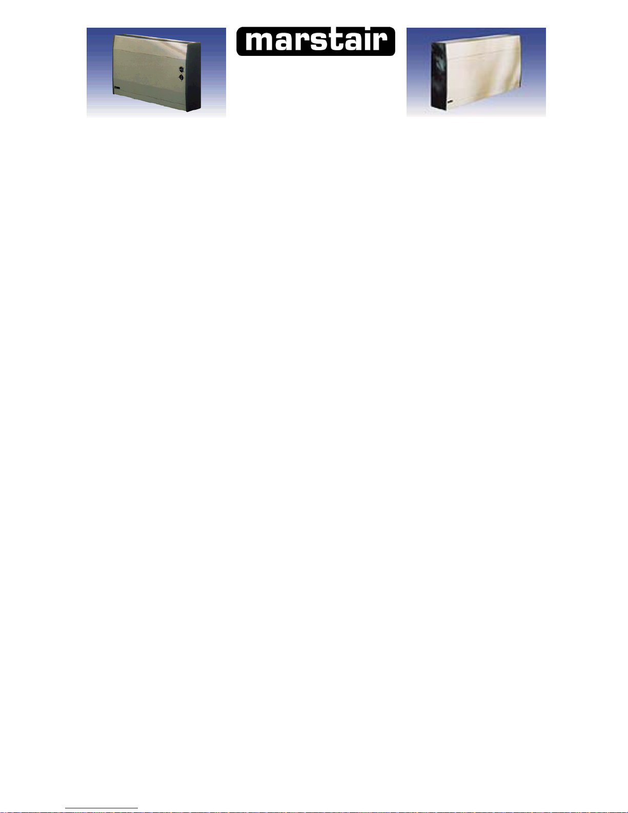
for HL/HLR WALL MOUNTED
SPLIT SYSTEMS
(with CEILING MOUNTED OPTION)
This manual provides technical and installation information for HL/HLR WALL MOUNTED split systems comprising:
INDOOR UNIT 526 series HL
527 series HLR
MATCHED WITH 550 series MCU or MCU+ condensing units
551 series MHPUE heat pump units.
INDEX PAGE
GENERAL Part numbers, dimensions and weights 2 - 3
Unit features/accessories 3
SELECTION Unit combinations, performance data 4
Airflows, sound pressure levels 5
ELECTRICAL Electrical data, recommended fuse sizes 6 - 7
UNIT HL/HLR 8
INSTALLATION MCU(+) and MHPUE units 9 - 10
Pipework, restrictors 10 - 12
Condensate removal, air deflection 12
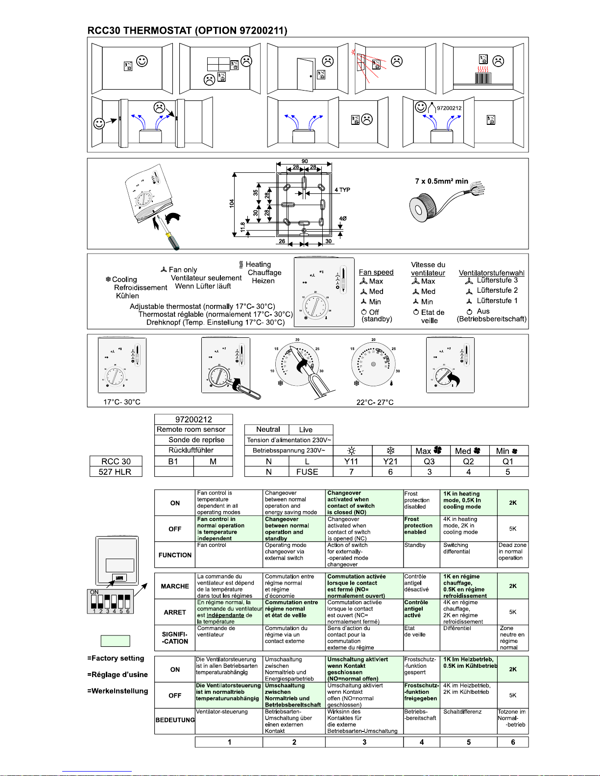
HLR remote controller 13
Electrical connections 14
HLR conversion to air conditioner mode 14
Evacuating and charging 15
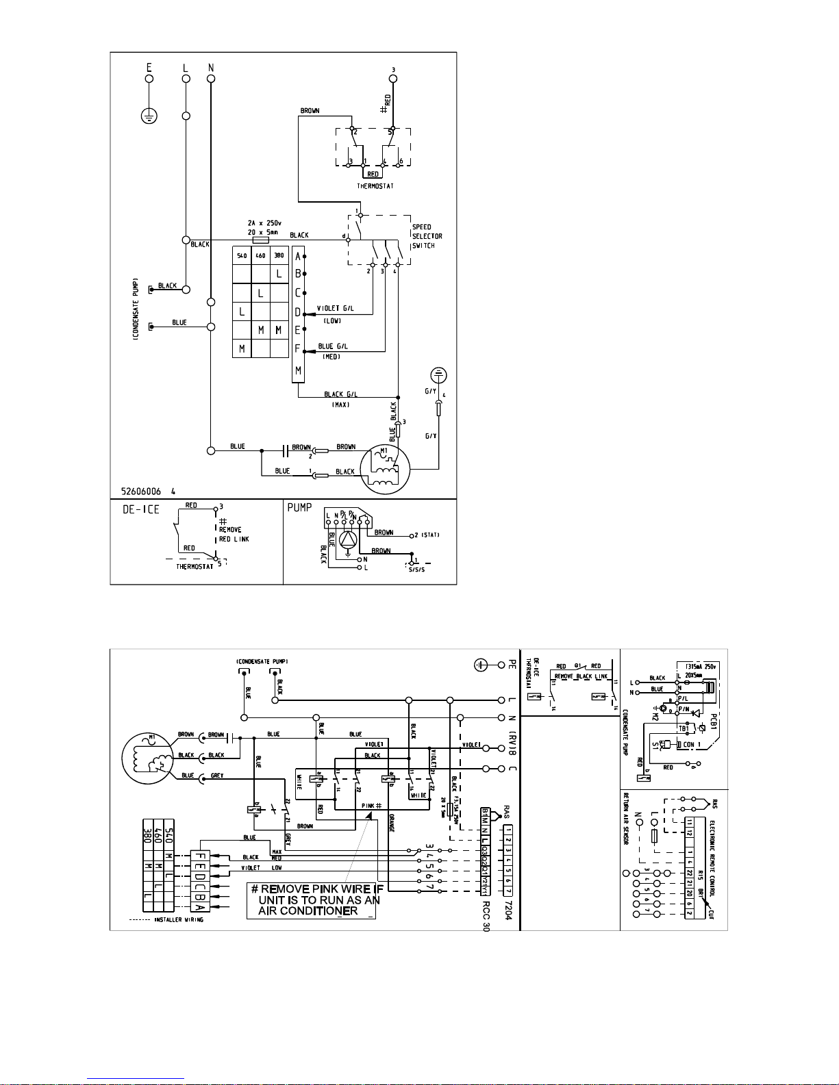
WIRING HL/HLR units 16
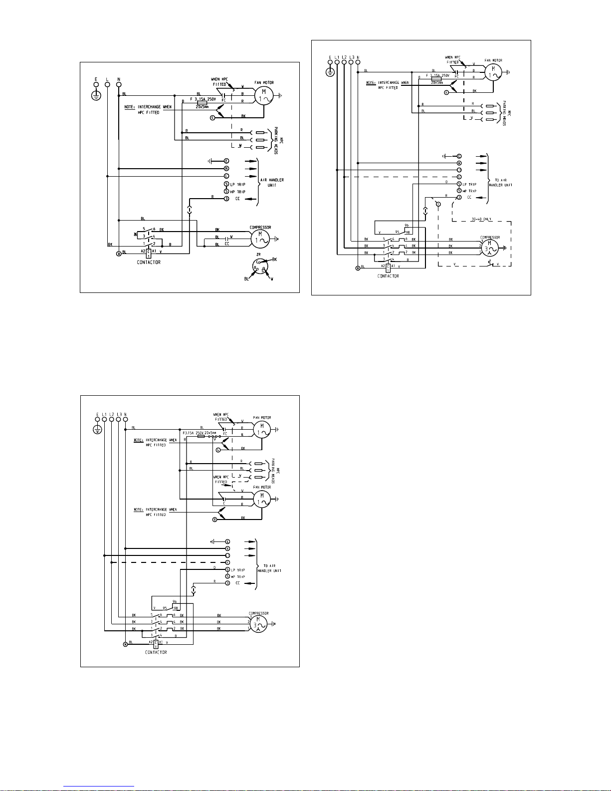
DIAGRAMS MCU(+) 17 - 18
MHPUE 19 - 20
Interconnection 21 - 23
OPERATION HL/HLR 24 - 25
MAINTENANCE User maintenance 25
HL/HLR KITS Ceiling mounting 26
Condensate pump 27 - 28
LPHW coil 29
De-ice thermostat 30
FAULT FINDING All units 31
TEV Ltd.,
Armytage Road, Brighouse,
West Yorkshire. HD6 1QF, UK.
Tel: +44 (0) 1484 405600
Fax: +44 (0) 1484 405620 52708017-06
Email: [email protected]
Page 2
-2-
TEV LIMITED - HL/HLR SPLIT SYSTEMS
The HL/HLR range of split systems comprises the 526 series HL indoor unit with in-built electromechanical controls, the 527
series HLR indoor unit with hard wired remote control, the 550 series outdoor condensing units and the 551 series heat pump
outdoor units.
By choosing appropriate combinations, the installer can provide:
AIR CONDITIONERS with a cooling range of 7.9 - 13.8 kW,
or HEAT PUMP systems with a cooling range of 7.9 - 12.8 kW, and a heating range of 9.1 - 13.2 kW with an outdoor
temperature of 7°C
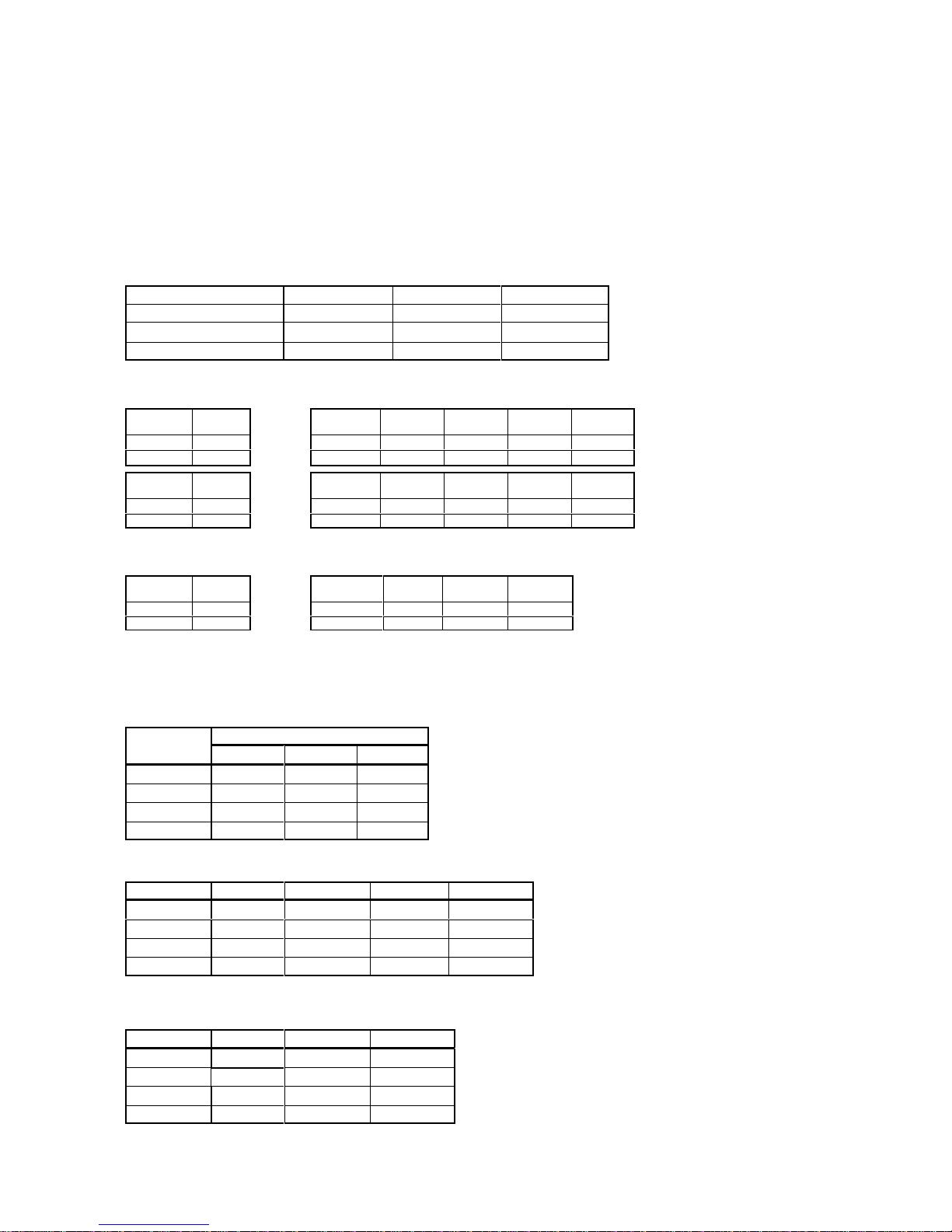
PART NUMBERS
526/527 Series HL/HLR INDOOR UNITS
HL Models 380 460 540
Part Number
52600010 52600009 52600007
HLR Models 380 460 540
Part Number
52700020 52700021 52700022
550 Series CONDENSING UNITS (MCU/MCU+)
MCU 1Ph
Scroll
MCU 90
MCU 3Ph
Scroll
MCU 90 MCU 100 MCU 130 MCU 165
R407C
55022052
R407C
55022058 55022059 55022060 55022062
R22
55022073
R22
55022079 55022080 55022081
55022083
MCU+ 1Ph
Scroll
MCU+ 90
MCU+ 3Ph
Scroll
MCU+ 90 MCU+ 100 MCU+ 130 MCU+ 165
R407C
55022009
R407C
55022016 55022017 55022018 55022020
R22
55022031
R22
55022037 55022038 55022039 55022041
551 Series HEAT PUMP UNITS (MHPUE)
MHPUE 1Ph
Scroll
MHPUE 90
MHPUE 3Ph
Scroll
MHPUE 90 MHPUE 100 MHPUE 130
R407C
55122008
R407C
55199014 55199015 55199016
R22
55122026
R22
55199032 55199033 55199034
UNPACKED DIMENSIONS AND WEIGHTS
HL/HLR INDOOR UNITS
Model HL/HLR
380 460 540
HEIGHT mm
786 786 786
WIDTH mm
1170 1320 1520
DEPTH mm
288 288 288
WEIGHT kg
58 62 69
CONDENSING UNITS
Model MCU(+) 90 MCU(+) 100 MCU(+) 130 MCU(+) 165
HEIGHT mm
820 820 1070 1070
WIDTH mm
1000 1000 1000 1000
DEPTH mm
350 350 425 425
WEIGHT kg
73 (76*) 81 101 103
* Single phase
HEAT PUMP OUTDOOR UNITS
Model MHPUE 90 MHPUE 100 MHPUE 130
HEIGHT mm
680 820 1070
WIDTH mm
905 1000 10001000
DEPTH mm
350 425 425
WEIGHT kg
75 (77*) 101 102
* Single phase
PACKED DIMENSIONS AND WEIGHTS
Page 3
-3-
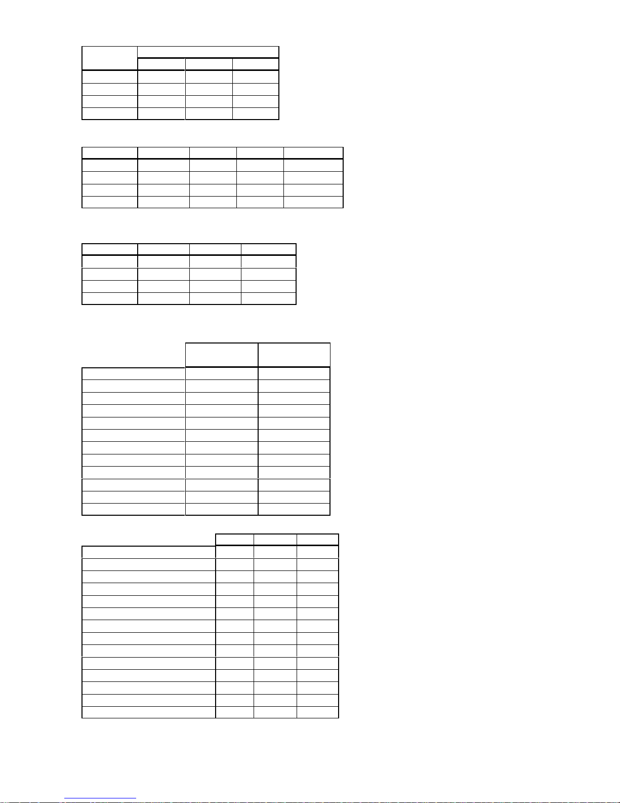
HL/HLR INDOOR UNITS
Model HL/HLR
380 460 540
HEIGHT mm
850 850 850
WIDTH mm
1210 1360 1560
DEPTH mm
305 305 305
WEIGHT kg
63 74 82
CONDENSING UNITS
Model MCU(+) 90 MCU(+) 100 MCU(+) 130 MCU(+) 165
HEIGHT mm
820 820 1080 1080
WIDTH mm
109 1090 1090 1090
DEPTH mm
390 390 465 465
WEIGHT kg
75 (78*) 83 105 107
* Single phase
HEAT PUMP OUTDOOR UNITS
Model MHPUE 90 MHPUE 100 MHPUE 130
HEIGHT mm
820 1080 1080
WIDTH mm
1090 1090 1090
DEPTH mm
390 465 465
WEIGHT kg
77 (79*) 105 106
* Single phase
FEATURES/ACCESSORIES
INDOOR UNITS
HL HLR
Manual air deflection
**
De-ice thermostat
**
3 fan speeds
STD STD
Remote hard wired control
*STD
Programmable timer
**
Condensate pump
**
Ceiling mounting kit
**
Floor mounting kit
**
LPHW coil
**
Long life washable filter
STD STD
Fresh air inlet facility
STD STD
Air deflectors
**
OUTDOOR UNITS
MCU MCU+ MHPUE
CSR hard start (1 phase)
** *
PTC hard start (1 phase)
** *
Fan speed head pressure control
*STDSTD
LP cutout auto
*STDSTD
HP cutout auto
* STD ---
HP cutout auto (with manual
--- --- STD
Isolator
** *
3 minute start time delay
*STDSTD
Wall mounting brackets
** *
Contactor
STD STD STD
Overload (standard on 3Ph)
** *
MHPUE condensate drain
--- --- *
Low ambient start
--- --- STD
Volt free relay
** *
Key: * = site option. STD = standard. --- = not available
Page 4
-4-
PRODUCT SELECTION
Combinations of indoor unit and condensing/heat pump unit can be chosen to give either air conditioning or heat pump
systems.
UNIT COMBINATIONS
Air Conditioning Systems Heat Pump Systems
HL/HLR MCU(+) HL/HLR MCU(+) HLR MHPUE
380 100 380 90 380 90
460 130 460 100 460 100
540 165 540 130 540 130
AIR CONDITIONER PERFORMANCE DATA
(All duties in kW)
UK CONDITIONS
ROOM 21°C/15°C
AMBIENT 27°C/19°C
EUROVENT (NEMA)
ROOM 27°C/19°C
AMB 35°C/24°C
TROPICAL
ROOM 29°C/19°C
AMB 46°C/24°C
MODEL
COMBINATIONLOW MIN SPEED MAX SPEED MAX SPEED EVAP MAX SPEED EVAP
HL/HLR+ MCU(+) TO SHR SENS TOT SH SEN TOTAL SHR SENS TOTAL SHR SENS
380 + 90 6.95 0.75 5.19 7.39 0.83 6.14 7.9 0.83 6.6 7.00 1.00 7.00
380 + 100 7.16 0.74 5.29 7.69 0.82 6.27 8.5 0.80 6.8 7.47 1.00 7.47
460 + 100 8.49 0.71 6.05 9.37 0.82 7.64 10.0 0.82 8.2 8.73 1.00 8.73
460 + 130 10.4 0.68 7.02 11.48 0.75 8.60 12.3 0.78 9.6 10.86 0.93 10.04
540 + 130 11.0 0.69 7.63 12.02 0.79 9.46 12.8 0.83 10.6 11.15 0.92 10.27
540 + 165 11.9 0.68 8.14 13.19 0.76 10.00 13.8 0.80 11.0 12.26 0.95 11.66
For medium speed duties, interpolate between minimum speed and maximum speed duties.
Rating conditions are to BS2852: Part 1: 1982: UK condition C; NEMA condition A; Tropical condition B.
HEAT PUMP PERFORMANCE DATA
a. Cooling, (kW, max speed outdoor unit fan).
UK CONDITIONS EUROVENT (NEMA)
ROOM 21°C/15°C
AMBIENT 27°
C/19°C ROOM 27°C/19°C AMBIENT 35°C/24°C
MIN SPEED INDOOR FAN MAX SPEED INDOOR FAN MAX SPEED INDOOR FAN
HL/HLR TOTAL SHR SENS TOTAL SHR SENS TOTAL SHR SENS
380 6.95 0.75 5.19 7.39 0.83 6.14 7.9 0.83 6.6
460 8.49 0.71 6.05 9.37 0.82 7.64 10.0 0.82 8.2
540 11.02 0.69 7.63 12.02 0.79 9.46 12.8 0.83 10.6
b. Heating, (Room 20°C/12°C with outdoor unit fan running at maximum speed).
HEATING OUTPUT AT 7°C AMBIENT HEATING OUTPUT AT -1°C AMBIENT
MAX SPEED INDOOR FAN MAX SPEED INDOOR FAN
HL/HLR kW COP kW COP
380 9.1 2.9 7.8 3.0
460 11.6 3.7 10.0 3.5
540 13.2 4.0 10.6 3.4
Page 5
-5-
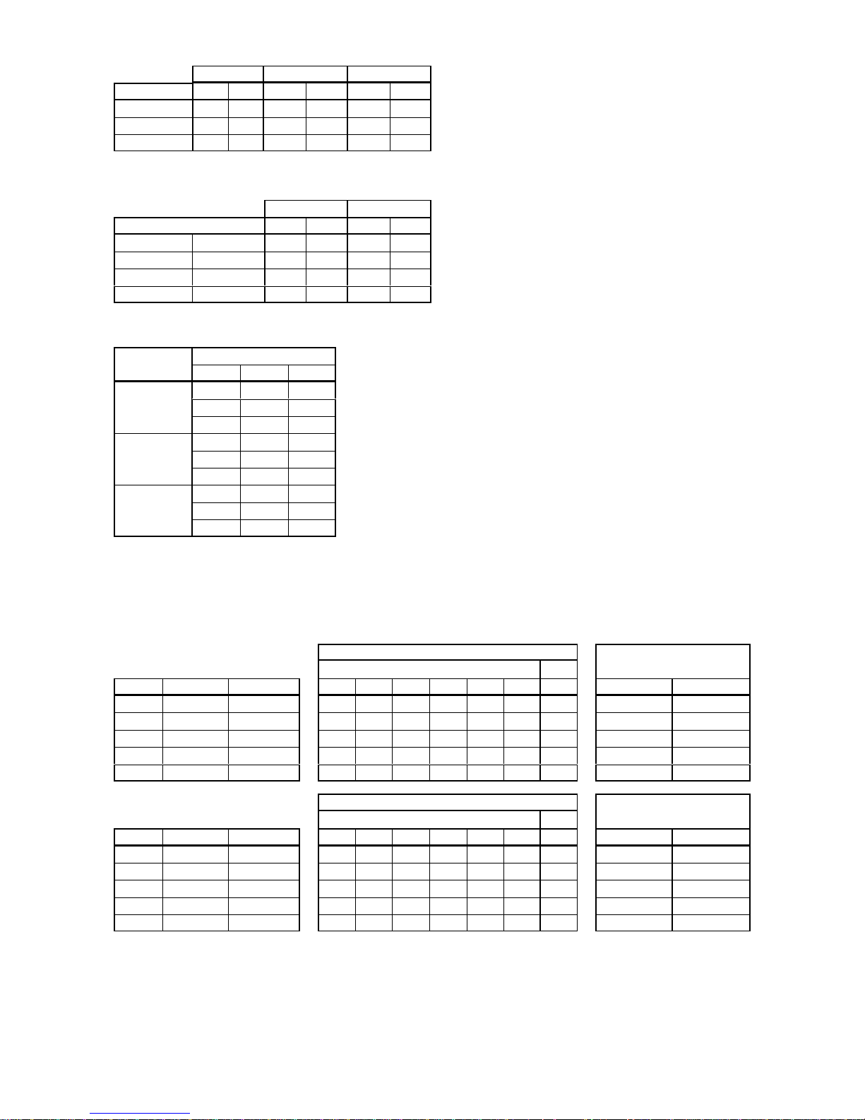
AIRFLOWS HL/HLR UNITS
Minimum Medium Maximum
HL/HLR CFM m
3
/s CFM m3/s CFM m3/s
380 805 0.38 1000 0.47 1145 0.54
460 850 0.40 1100 0.52 1400 0.66
540 1000 0.47 1290 0.61 1650 0.78
AIRFLOWS OUTDOOR UNITS
MIN Speed MAX Speed
Model CFM m
3
/s CFM m3/s
MCU(+) 90 --
1440 0.68 2420 1.14
MCU(+) 100 MHPUE 90
1440 0.68 2420 1.14
MCU(+) 130 MHPUE 100
2840 1.34 3690 1.74
MCU(+) 165 MHPUE 130
2840 1.34 3690 1.74
SOUND PRESSURE LEVELS HL/HLR UNITS
Sound Pressure Levels
MODEL Speed dBA NC
380
Min
50 42
Med
53 47
Max
57 51
460
Min
47 41
Med
53 47
Max
59 53
540
Min
48 42
Med
53 48
Max
59 53
Sound Pressure Levels are dB relative to 2 x 10
-5
N/m2 and are calculated from the results under anechoic conditions and are
quoted as an average of all points on a hemisphere of a radius of 3m away from the centre of the unit.
SOUND POWER and SOUND PRESSURE LEVELS
550/551 SERIES MCU, MCU+ and MHPUE
MAXIMUM SPEED
SOUND POWER LEVELS
SOUND PRESSURE
LEVELS
Frequency Hz
MCU(+) MHPUE Compressor 125 250 500 1K 2K 4K dBA dBA NC
90 90
Scroll 81.8 71.8 69.2 68.6 63.1 57.4 72.8 52.3 47
100 --
Scroll 79.4 73.7 71.5 68.5 63.8 58.1 73.4 52.9 47
-- 100
Scroll 79.0 69.7 68.6 65.9 61.2 55.2 71.0 50.5 44
130 130
Scroll 73.0 70.3 70.0 68.8 65.0 56.7 72.6 52.1 47
165 --
Scroll 73.1 70.3 70.1 68.9 65.5 57.5 73.1 57.2 51
MINIMUM SPEED
SOUND POWER LEVELS
SOUND PRESSURE
LEVELS
Frequency Hz
MCU(+) MHPUE Compressor 125 250 500 1K 2K 4K dBA dBA NC
90 90
Scroll 79.0 65.4 64.9 61.5 58.5 53.7 67.6 47.1 40
100 --
Scroll 75.3 69.4 70.9 63.7 59.7 53.6 70.4 49.9 46
-- 100
Scroll 67.1 67.9 65.0 61.2 56.3 51.0 66.9 46.4 40
130 130
Scroll 65.4 66.7 68.1 66.1 63.1 53.0 70.0 49.5 44
165 --
Scroll 65.5 66.9 67.3 65.1 64.2 54.0 72.6 52.6 47
Sound Power Levels were obtained in full accordance with the direct method of ISO 3741: 1988. Quantities are shown in dB with
a standard reference of 1 pW.
Sound Pressure Levels are dB relative to 2 x 10
-5
N/m2 and are calculated from the results under free field conditions and are quoted
as an average of all points on a sphere of a radius of 3m away from the centre of the unit (in cooling mode); (add 3dBA or 3NC for
units at an intersection of a wall, add 1dBA or 1NC for high level wall mounted units).
Page 6
-6-
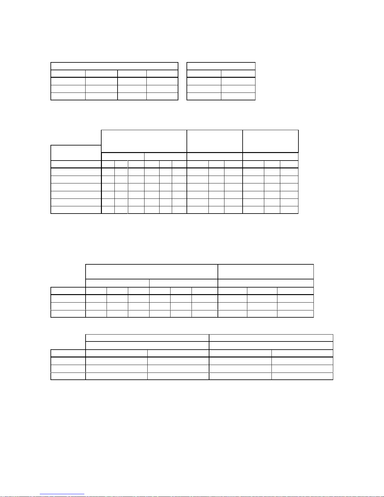
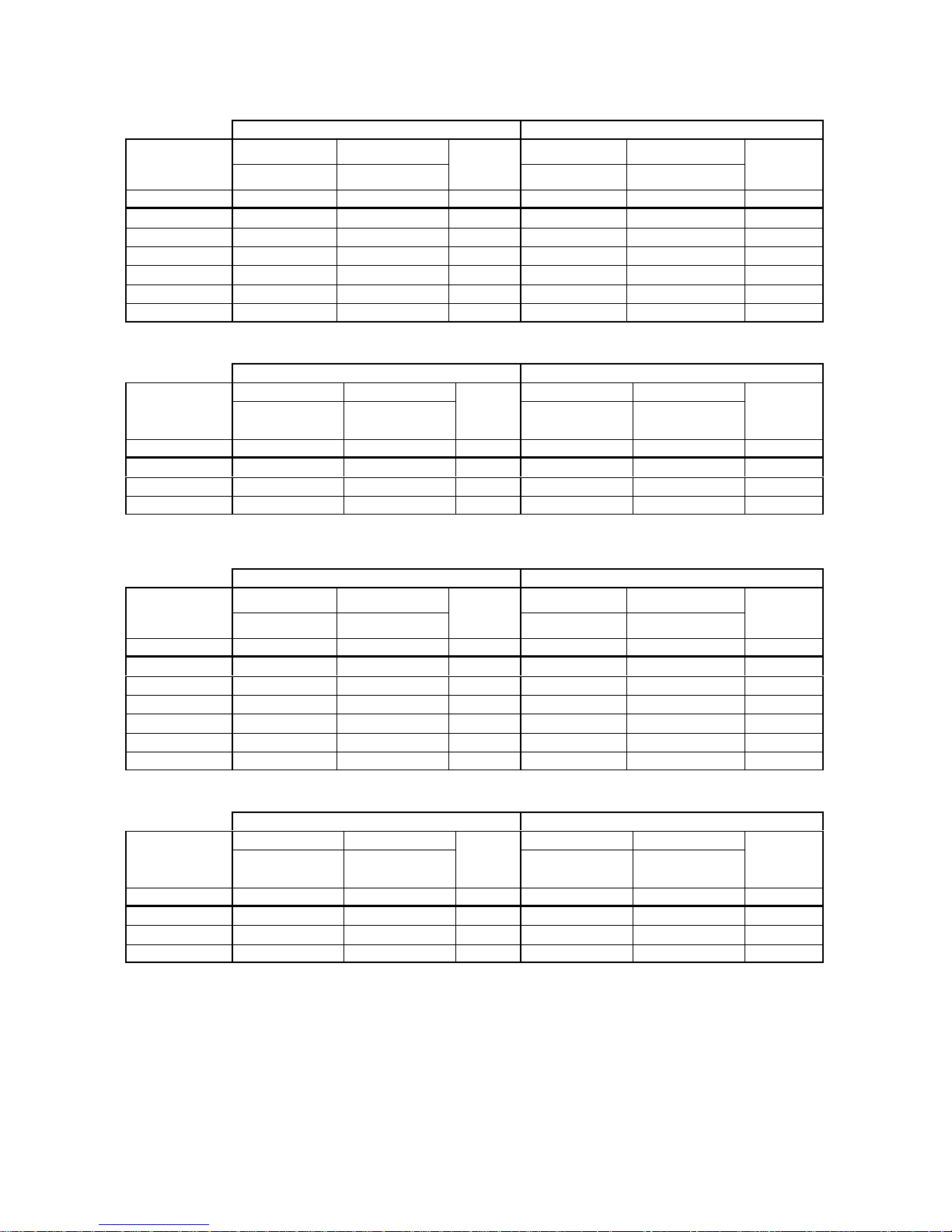
ELECTRICAL DATA (Cooling Data rated at EUROVENT (NEMA) conditions)
(Heating Data rated at 20°C/12°C indoor; 7°C/6°C ambient)
a) R22 Air Conditioning Systems
Single Phase Supply 230Volts - 50Hz Three Phase Supply 400 Volts - 50Hz
MODEL
COMBINATION
INPUT FULL LOAD AMPS
SYSTEM
MAX.
STARTING
CURRENT
INPUT FULL LOAD AMPS
SYSTEM
MAX.
STARTING
CURRENT
Cooling Cooling Cooling Cooling
HL/HLR + MCU(+) kW AMPS AMPS kW A/PH A/PH
380 + 90 4.3 17.5 116 4.3 8.3 50
380 + 100 -- -- -- 4.3 8.4 53
460 + 100 -- -- -- 4.3 8.5 53
460 + 130 -- -- -- 4.9 9.0 64
540 + 130 -- -- -- 4.9 9.2 64
540 + 165 -- -- -- 6.3 11.1 73
b) R22 Heat Pump Systems
Single Phase Supply 230Volts - 50Hz Three Phase Supply 400 Volts - 50Hz
MODEL
COMBINATION
INPUT FULL LOAD AMPS
SYSTEM
MAX.
STARTING
CURRENT
INPUT FULL LOAD AMPS
SYSTEM
MAX.
STARTING
CURRENT
STD.
MODEL
STD.
MODEL
STD.
MODEL
STD.
MODEL
HL/HLR + MHPUE kW AMPS AMPS kW A/PH A/PH
380 + 90 4.3 17.5 114 4.3 8.3 60
460 + 100 -- -- -- 4.3 8.7 63
540 + 130 -- -- -- 4.9 9.2 74
c) R407C Air Conditioning Systems
Single Phase Supply 230Volts - 50Hz Three Phase Supply 400 Volts - 50Hz
MODEL
COMBINATION
INPUT FULL LOAD AMPS
SYSTEM
MAX.
STARTING
CURRENT
INPUT FULL LOAD AMPS
SYSTEM
MAX.
STARTING
CURRENT
Cooling Cooling Cooling Cooling
HL/HLR + MCU(+) kW AMPS AMPS kW A/PH A/PH
380 + 90 4.4 18.2 116 4.4 8.4 50
380 + 100 -- -- -- 4.6 8.5 53
460 + 100 -- -- -- 4.6 8.6 53
460 + 130 -- -- -- 4.9 9.1 64
540 + 130 -- -- -- 4.9 9.3 64
540 + 165 -- -- -- 6.5 11.1 73
d) R407C Heat Pump Systems
Single Phase Supply 230Volts - 50Hz Three Phase Supply 400 Volts - 50Hz
MODEL
COMBINATION
INPUT FULL LOAD AMPS
SYSTEM
MAX.
STARTING
CURRENT
INPUT FULL LOAD AMPS
SYSTEM
MAX.
STARTING
CURRENT
STD.
MODEL
STD.
MODEL
STD.
MODEL
STD.
MODEL
HL/HLR + MHPUE kW AMPS AMPS kW A/PH A/PH
380 + 90 4.4 18.2 114 4.4 8.4 60
460 + 100 -- -- -- 4.6 8.7 63
540 + 130 -- -- -- 4.9 9.3 74
Page 7
-7-
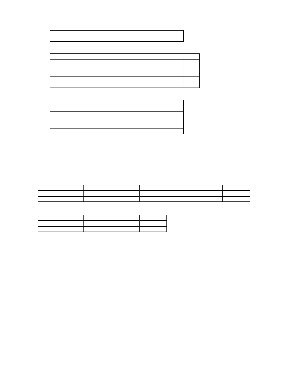
Electrical Loads (At 230 Volts 50 Hz 1Ph or 400 Volts 50 Hz 3PhN)
HL/HLR
380 460 540
FAN MOTOR
1.3 1.4 1.6
MCU(+)
90 100 130 165
FAN MOTOR
1.0 1.0 1.2 1.2
R407C COMPRESSOR (1 PHASE) NOMINAL FLA
15.9------
R407C COMPRESSOR (3 PHASE) NOMINAL FLA
6.1 6.2 6.7 8.5
R22 COMPRESSOR (1 PHASE) NOMINAL FLA
15.2------
R22 COMPRESSOR (3 PHASE) NOMINAL FLA
6.0 6.1 6.4 8.3
MHPUE
90 100 130
FAN MOTOR
1.0 1.2 1.2
R407C COMPRESSOR (1 PHASE) NOMINAL FLA
15.9 -- --
R407C COMPRESSOR (3 PHASE) NOMINAL FLA
6.1 6.2 6.7
R22 COMPRESSOR (1 PHASE) NOMINAL FLA
15.2 -- --
R22 COMPRESSOR (3 PHASE) NOMINAL FLA
6.0 6.1 6.4
Recommended Fuse Sizes (R22 and R407C systems)
The system and its supply/interconnecting wiring must be protected by fuses, preferably High Rupture Current (HRC)
motor rated types (to EN 60269) or miniature circuit breakers (to EN 60898) or local codes having similar time lag
characteristics, that allow starting of the compressor yet still afford close overcurrent protection under running
conditions. The ratings below are for HRC motor rated fuses.
Air Conditioners
HL/HLR + MCU(+) 380 + 90 380 + 100 460 + 100 460 + 130 540 + 130 540 + 165
1 Phase cool only
32 -- -- -- -- --
3 Phase cool only
16 16 16 16 16 20
Heat Pumps
HL/HLR + MHPUE 380 + 90 460 + 100 540 + 130
1 Phase cool only
32 -- --
3 Phase cool only
16 16 20
Page 8
-8-
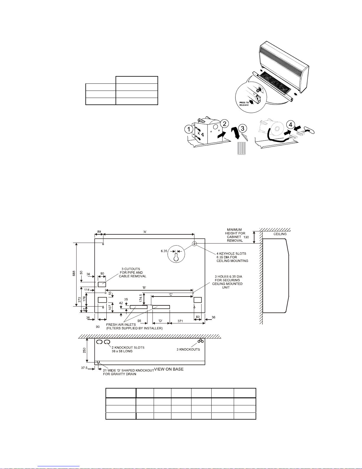
HL/HLR Installation
An envelope containing important user information is supplied with the indoor unit. Please pass this to the end user.
Indoor Unit Cabinet Removal
1. Press the filter tray at both sides to spring it and the filter out (Fig.1).
2. Remove the two outer self tap screws then release the quarter turn fasteners.
3. Pivot the cabinet forward from the bottom and lift upwards to clear the
chassis top flange and remove, this will reveal the polystyrene fan scrolls
which should NOT be removed.
Fig. 1
Weight (kg)
HL/HLR 380
61
HL/HLR 460
62
HL/HLR 540
69
4. The unit is shipped with a bracket to protect the
motor during transit. Remove and discard
the bracket, and fit the motor wiring plug and
socket as shown.
Mounting
1. It is generally easier to fit kits prior to mounting the unit and brazing the pipework.
2. Ensure that the wall or ceiling will accept the operating weight of the unit.
3. Mark off the mounting holes as Fig.2 and drill holes to suit M6 rawlbolt shields or equivalent fasteners.
Allow 130mm minimum from ceiling to holes for cabinet removal on wall mounted units.
Allow 150mm at the base plate (wall or ceiling mounted) to maintain design airflows.
4. If a fresh air facility is required, apertures must be prepared as shown in Fig.2. This must be suitably lined and screened
on the internal wall to prevent brick dust from entering the unit, (apertures are 35mm high), filters are fitted as standard.
5. Mount the unit and secure the fixings. On ceiling mounted uni ts t wo extra holes are provided for screws to prevent
movement on the keyhole slots.
6. Check the unit is square and level. Use the extra self tap screws to additionally secure ceiling mounted cabinets.
Fig. 2
Model 'A' 'B' 'C' 'D'
No. of
air inlets
No. of
spaces
HL/HLR 380
961 921 461 250 2 1
HL/HLR 460
1111 1071 536 300 2 1
HL/HLR 540
1311 1271 626 240 3 2
Page 9
-9-
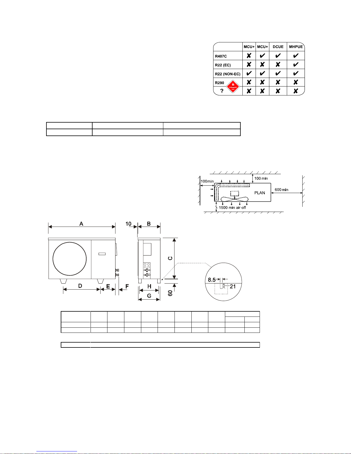
MOUNTING HOLES
550 Series CONDENSING UNITS and 551 Series HEAT PUMP OUTDOOR UNITS INSTALLATION
These outdoor units are for use in systems which use expansion devices.
MCU = standard condensing unit MCU+ = standard condensing unit + FSC + LP MHPUE = electronic heat pump outdoor unit
Some units are supplied with a number of loose restrictors which may be
required, depending on the indoor unit it is matched with and whether the unit
is to be run in NEMA conditions; refer to page 11.
The installer needs:
2 open ended spanners for securing the flare fittings
A 4 or 5mm Allen Key for the valves (dependant on valve type).
Note: It is easier to fit kits prior to mounting the unit.
These units are designed to stand on a flat surface. If the unit is to be wall mounted the following kits are available.
(TEV cannot accept liability for installers own mounting arrangements).
Model MCU(+) 90 - 100/MHPUE 90 MCU(+) 130 - 165/MHPUE 100 - 130
Mounting Bracket Kit
55021100 55021101
Whether floor or wall mounted, it is essential that the mounting surface is capable of supporting the unit weight (shown over).
Leave space around the unit for air circulation and access for installation and maintenance.
MOUNTING: MCU(+) 90 - 100 and MHPUE 90
All dimensions are in
millimetres.
MODEL ABCDEFGH
Weight (kg)
1 Ph 3
MCU(+) 90
1000 350 760 495 250 70 345 325 76 73
MCU(+) 100
1000 350 760 495 250 70 345 325 -- 81
MHPUE 90
1000 350 760 495 250 70 345 325 77 75
Page 10
-10-
B
60
A10
C
D
E
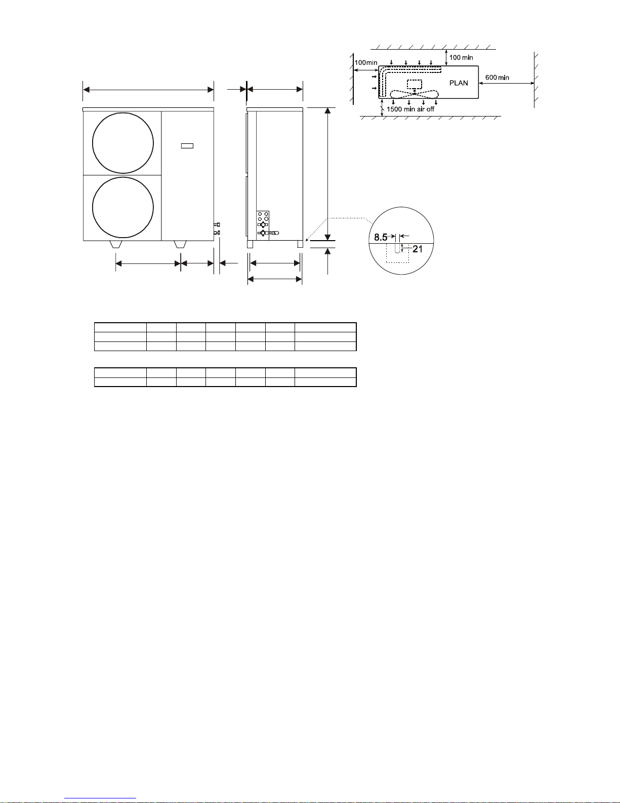
MOUNTING HOLES
417
397
425
MOUNTING: MCU(+) 130 - 165 and MHPUE 100 - 130
All dimensions are
in millimetres.
MODEL A B C D E Weight (kg)
MCU(+) 130
1000 1020 495 251 100 101
MCU(+) 165
1000 1020 495 251 100 103
MHPUE 100
1000 1020 495 251 100 101
MHPUE 130
1000 1020 495 251 100 102
APPLICATION
1. To maximise performance, pipe runs should be kept as short as possible, avoiding sharp bends. However,
individual pipe runs to a maximum of 80m, including 20m lift, are permissible provided good refrigeration practice is
followed.
Published performance duties are based on 7.5m pipe runs. Correctly sized pipes for each installation, and fitting
the correct expansion orifice (restrictor) will result in no significant loss of capacity on extended pipe runs.
a) Pipe sizes are based on:-
Minimum of 3.8 m/s (750 fpm) suction gas velocity for horizontal or downflow.
Minimum of 7.6 m/s (1500 fpm) suction gas velocity for upflow.
Maximum of 15.2 m/s (3000 fpm) suction gas.
b) Where vertical risers exceed 3m, oil traps must be formed in the pipe. This will help ensure that oil returns to
the compressor. Typically fit an oil trap every 3m with a trap at the bottom of the riser.
2. Add 25 grams of refrigerant oil (Polyolester Oil) for every 350 grams of charge added to systems with pipe runs
exceeding 25m, up to a maximum of 300 grams; preferably by slowly pumping into the suction side with the unit
running, after charging the system.
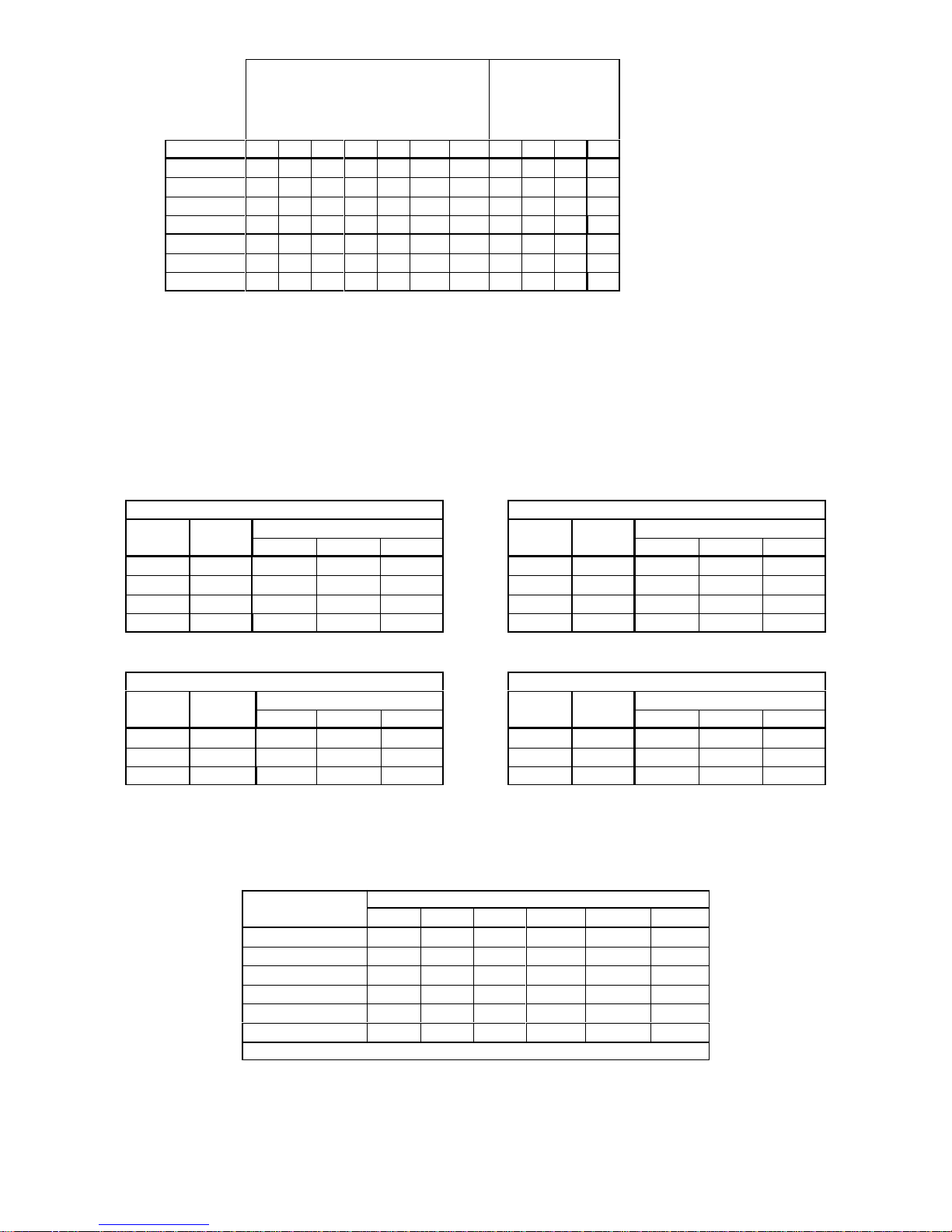
3. The maximum pipe lengths to be used for each pipe size and outdoor unit are shown in the table opposite. Use of
these sizes and lengths is recommended in order to achieve optimum system performance.
Page 11
-11-
MAXIMUM EQUIVALENT LENGTH OF
SUCTION LINE
PIPES (M)
EXPANSION
LINES
UNIT 3/8 1/2 5/8 3/4 7/8 1-1/8 1-3/8 3/8 1/2 5/8 3/4
MCU(+) 90
10 25 55 80 20 80
MCU(+) 100
7.52245 80 1580
MCU(+) 130
15 30 80 12 60 80
MCU(+) 165
8 18 60 80 7.5 40 80
MHPUE 90
25 55 80 20 60 80
MHPUE 100
22 45 80 15 50 80
MHPUE 130
15 30 80 12 60 80
RESTRICTORS
Outdoor units are supplied with cooling restrictors fitted in an expansion assembly; refer to the following tables for any
restrictor changes: those ticked do not require changing.
Where appropriate,the alternative restrictor is supplied in either the indoor or the outdoor unit.
A capillary is fitted to HLR units for refrigerant control during a heat pump heating cycle.
RESTRICTOR MATCHES
AIR CONDITIONING AT UK CONDITIONS AIR CONDITIONING AT NEMA CONDITIONS
3 = NO RESTRICTOR CHANGE NEEDED RESTRICTOR CHANGE NEEDED
MCU(+)
Restrictor
Fitted
HL/HLR
MCU(+)
Restrictor
Fitted
HL/HLR
380 460 540 380 460 540
90
63
3
90
63 066
100
68
33
100
68 071 71
130
0.071
33
130
71 74 074
165
79
3
165
79 083
HEAT PUMP COOLING AT UK CONDITIONS HEAT PUMP COOLING AT NEMA CONDITIONS
3 = NO RESTRICTOR CHANGE NEEDED RESTRICTOR CHANGE NEEDED
MHPUE
Restrictor
Fitted
HL/HLR
MHPUE
Restrictor
Fitted
HL/HLR
380 460 540 380 460 540
90
67
3
90
67 070
100
68
3
100
68 71
130
76
3
130
76 080
3 = no change needed
4. In calculating equivalent lengths of pipe runs, the effect of bends and fittings mu st b e taken into account. The table
below covers the fittings most likely to be encountered in this type of installation. The equivalent lengths of all the
fittings in a pipe run must be added together and the total added to the actual length of pipe in the run, in order to
calculate the total equivalent length.
Pipe Size (outside diameter in inches)
Fitting 3/8 1/2 5/8 3/4 7/8 1-1/8
45° Bend
0.12 0.15 0.18 0.21 0.24 0.3
90° Bend R/d = 1
0.37 0.43 0.49 0.55 0.61 0.79
90° Bend R/d = 1.5
0.24 0.27 0.30 0.37 0.43 0.52
180° Bend C/d = 1.5
0.73 0.91 1.10 1.28 1.46 1.83
180° Bend C/d = 2.5
0.46 0.55 0.64 0.76 0.85 1.07
90° Elbow
0.67 0.85 1.04 1.25 1.46 1.89
R = Radius of bend d = Diameter of tube C = Centres of bend
Fitting losses, in equivalent straight lengths of pipe (metres).
5. Use the shortest possible route, avoiding sharp bends.
6. Fully insulate both the suction and expansion lines, including the expansion device, since both lines may sweat.
Page 12
-12-
Refrigeration Installation
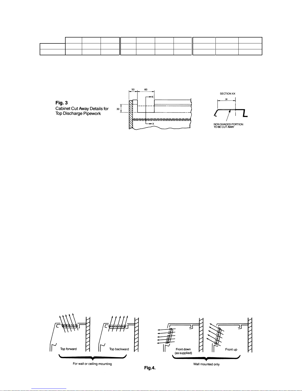
1. The refrigerant connections are terminated on the left hand side of the indoor coil and the lower front of the right end
panel on outdoor units; (indoor units are brazed connections, outdoor units are flare fittings).
Units are supplied with the following pipes: (HL are the same as HLR models; MCU+ are the same as MCU models).
HLR 380 HLR 460 HLR 540 MCU 90 MCU 100 MCU 130 MCU 165 MHPUE 90 MHPUE 100 MHPUE 130
Expansion
1/2" 1/2" 1/2" 1/2" 1/2" 1/2" 1/2" 1/2" 1/2" 1/2"
Suction
5/8" 5/8" 5/8" 5/8" 3/4" 3/4" 3/4" 3/4" 3/4" 3/4"
2. Using a tube cutter, remove sealed ends of suction and expansion pipes on the indoor unit. This will release a small
holding charge of dry nitrogen.
3. Pipe exit will normally be via knockouts in the base or cutouts in the back panel.
Alternatives are:
For top left hand exit, turn your pipework through 180° and exit via the gap provided in the back panel. The cabinet
will need to be locally notched as Fig. 3 - do not completely cut away as this will weaken the structure.
BOTTOM RIGHT HAND EXIT can be achieved by running pipework underneath the scroll attached to the back panel.
Remove the lower grille (4 screws) for access, fit suitable lengths of insulation to the pipework and braze in. It is
recommended that the liquid and suction lines be kept to ½" and 5/8" respectively until exit, when the full pipe size can
be run. Exit is preferably made via notches to be cut to suit in the right hand side panel.
4. It is recommended that the drip tray is removed during brazing to prevent if being melted. Remove the top two screws
on the front scroll, and remove drip tray and the support bracket together.
5. Connect pipework between units ensuring:
a) Only refrigeration quality copper is used.
b) The ends are capped on tubes and parts when not working on them to prevent moisture or dirt entering the
system.
c) If pipes are brazed, use a copper phosphorous alloy containing 5% silver, ensuring that dry nitrogen is passed
through the components involved to prevent oxidation.
d) The suction and expansion lines are fully insulated, including inside the cabinet of the indoor unit up to the drip
deflector. Bend pipework back to ensure it is over the drip tray; if in doubt, use non-drip tape.
e) The system is leak tested and evacuated before final charging.
6. If a sight glass is fitted to aid charging it must be positioned before the expansion device on the outdoor unit.
Condensate Drain
The condensate drain connection is at the left hand end of the drain tray. A ½" O.D. plastic drain pipe is provided in the
drain tray sump for connection with non-kink plastic tubing secured with a suitable clip. Should it be necessary for the
drain pipe to go through the bottom of the unit a knockout is provided at the left hand end of the base plate.
The drain line must have a constant fall to open drain using a ''U' trap if required. Check that the water will run freely and
that there are no leaks.
Details of ceiling mounted drain and fitting of optional condensate pump are provided on pages 25 to 27.
Discharge Grille position
The discharge grille is supplied for front down discharge. The alternatives are achieved by:
i) Remove and retain grille and blanking panel screws (12 in total).
ii) Slacken but do not remove all other fixing screws.
iii) Remove blanking panel.
iv) Remove grille.
v) Slide blanking panel into new position and fix.
vi) Clip panel location bracket under return edge of blanking panel and screw down into return edge of front panel.
Page 13
-13-
Page 14

-14-
ELECTRICAL CONNECTIONS
Supply, control and connecting cables are fitted by the installer.
Installer wiring should be carried out in accordance with local and national codes.
Cables must be size compatible with the recommended fuse for a given system. (see page 7 for fuse ratings).
A double pole isolator switch should be positioned adjacent to the indoor unit.
The equipment must be earthed.
Systems should have the supply taken to the outdoor unit; a single phase supply (L1), is run back to the indoor unit.
Power should be connected to the outdoor unit for 4 hours to allow the lubricating oil to be heated prior to compressor
start up.
INDOOR UNIT WIRING
The connections for internal wiring for indoor units are made at the right hand side of the unit. Mains supply should be
routed to the terminal blocks in the unit through the slots behind the fan motor if brought from below.
Cable grips are provided above the terminal block to give a secure installation.
Note that the electrics assembly can be quickly removed if required by removing 2 screws from the evaporator flange and
springing the electrics mounting plate free of locating slots in the rear panel. These screws and washers form the earth
connection to the air handler and must be securely re-fitted.
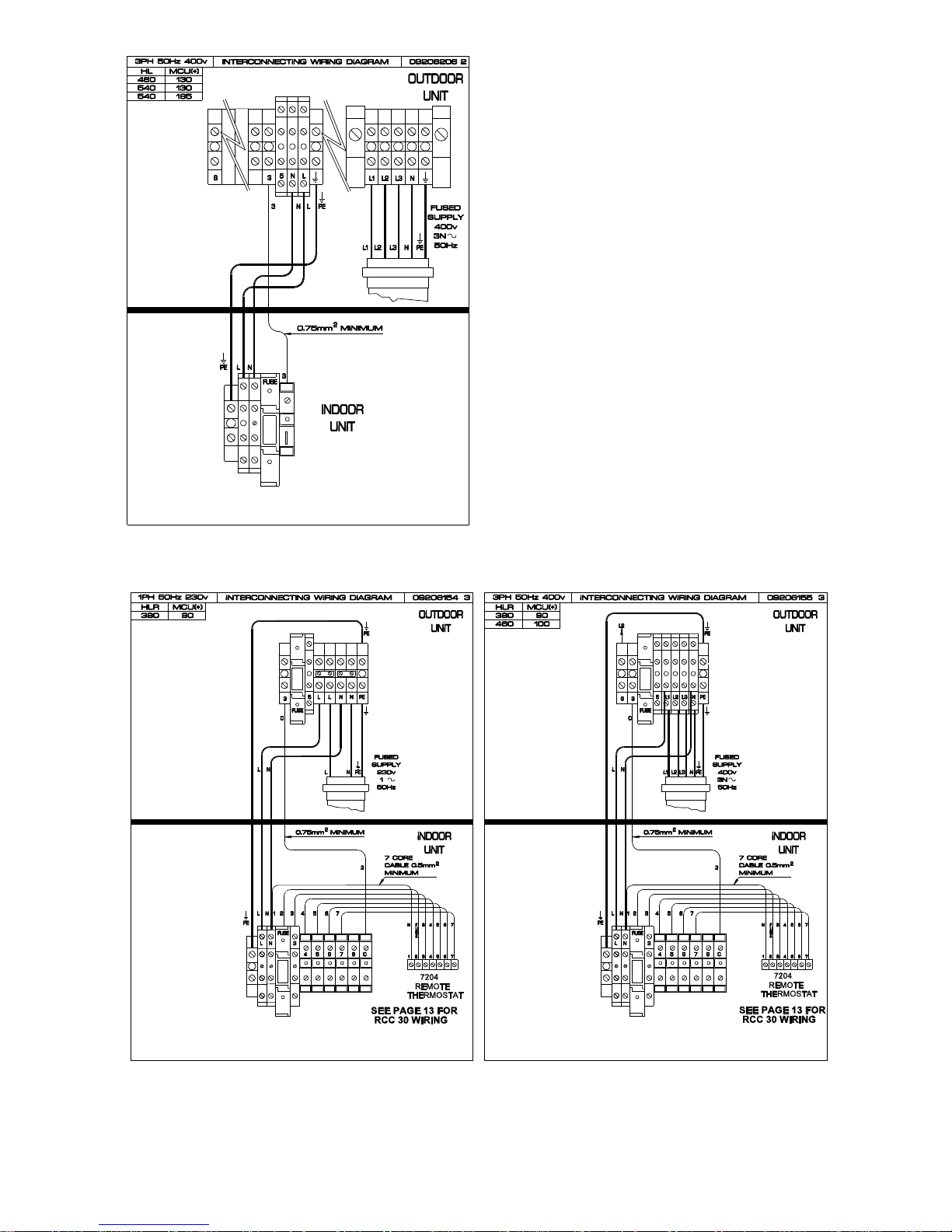
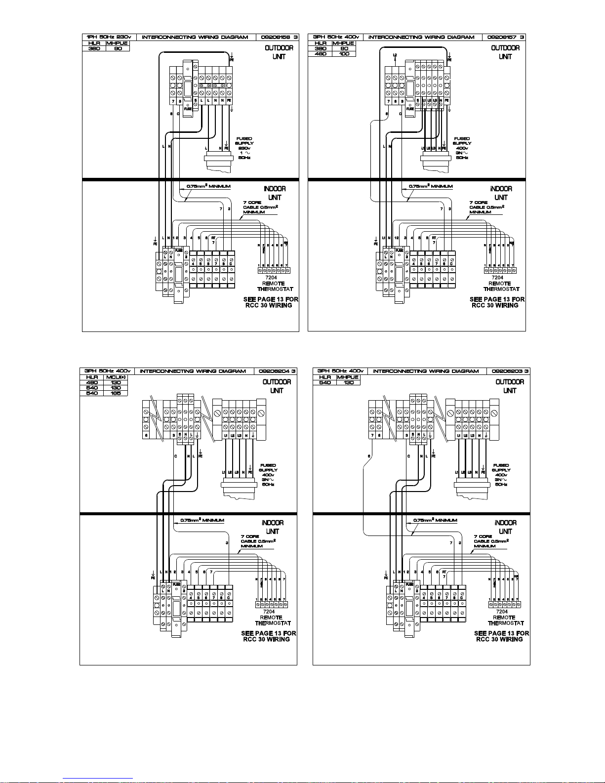
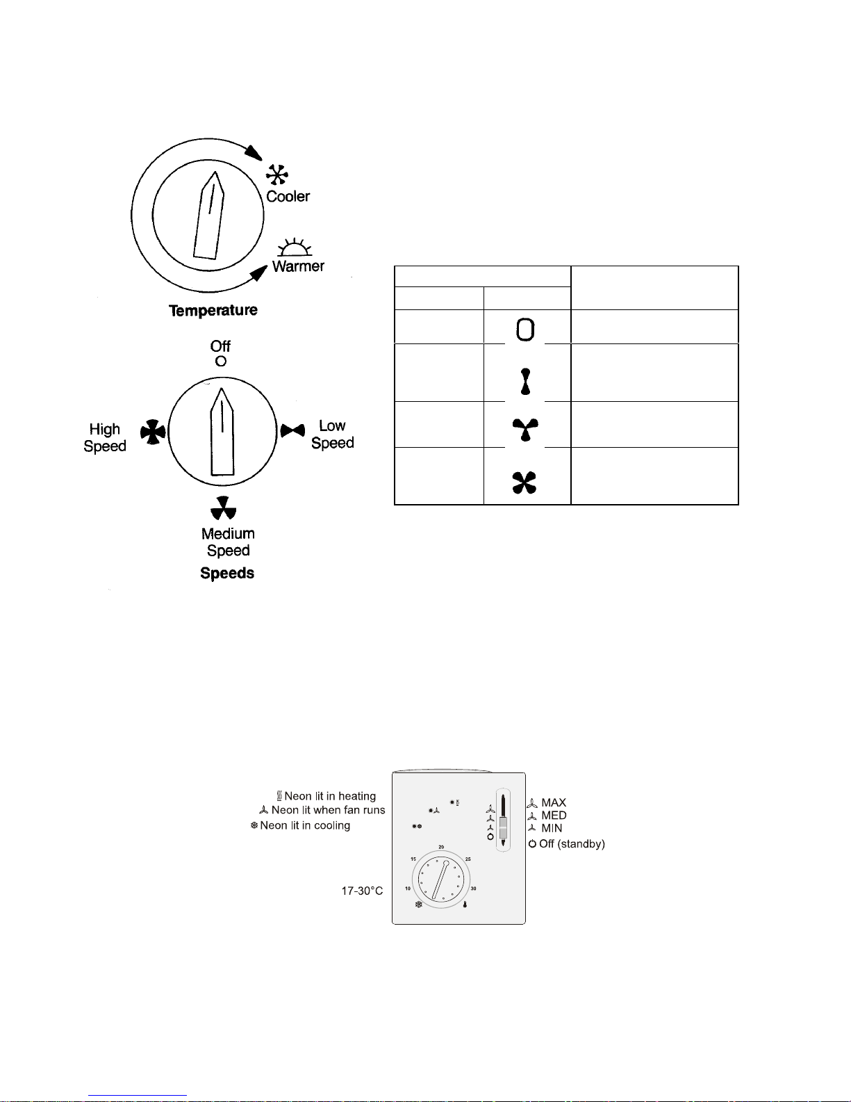
Make sure all connections are secure and all wires are clear of rotating parts. Interconnect as shown on pages 21 to 23.
CONVERSION OF HLR INDOOR UNIT FOR AIR CONDITIONER USE
The HLR indoor unit is supplied wired for use as a heat pump.
For air conditioner mode, remove the pink link between relay 1 terminal 14 and relay 2 terminal 22.
OUTDOOR UNIT WIRING
Cable entry for the outdoor unit electrics is through the cabinet to a terminal block.
MCU+, MHPUE and DCUE units are supplied wired via a head pressure controller to give maximum control. Ensure
that all connections are secure and that both units are earthed.
MCU unit fan motors have a high speed (black) wire and a low speed (red) wire; the speed not being used is w ired into
a dummy terminal. They are supplied wired for low fan speed, which is suitable for temperate climates. If continuous
running is expected at ambient temperatures of 35°C or higher, change to high speed by interchanging the black and red
wires, i.e. black to fused terminal, red to terminal 4 (single fan units) or terminals 4 and 8 (double fan units).
SCROLL COMPRESSOR ROTATION
On 3 Phase units it is possible for the scroll compressor to run backwards. This becomes obvious on start u p; the
compressor will not develop a normal running pressure differential and the top will not become warm. It may be
excessively noisy. If this happens, switch off the mains power and exchange any two of the phases supplying the unit.
This will correct the rotation of the compressor.
DATA PLATES
Because of the ability to match indoor and outdoor units, the data plates only give information on either an indoor or
outdoor unit. To obtain the system details, input power and currents from indoor and outdoor units should be added.
FIRE LINK
In order to automatically switch off the fan in the event of a fire, it is necessary to fit an external switch (240V, 3A, closed
to run, volt free contact) to:-
HLR units
: in the installer wire between terminal block terminal 2 and the Marstair remote control thermostat terminal
2(96000320) or L (97200211)
HL units
: in the internal (black) wire between the fuse and rotary switch terminal 'd'. This external switch should be
operated by the building's fire alarm or BMS system.
Page 15
-15-
EVACUATING
Connect a vacuum pump to the service ports on the outdoor unit valves and evacuate the interconnecting pipework and
indoor unit to 1000 microns (1 Torr) or better and allow to be held for a minimum of 15 minutes.
After evacuating the indoor unit and interconnecting pipework, open the outdoor unit valves using a 5mm Allen key. The high
and low side pressures should equalise within a minute.
Run the system for a few minutes to allow it to stabilize.
If a manual HP cutout is fitted, ensure that the reset button is depressed (in the compressor compartment, outdoor unit).
MHPUE units: if no extra refrigerant is to be added REMOVE link JP6 (in the electrics box, outdoor unit, identified by a white
label), otherwise the unit will always run at full speed.
ADDING REFRIGERANT
Each outdoor unit is charged with refrigerant, as below:-
MCU(+)90 MCU(+) 100 MCU(+) 130 MCU(+) 165 MHPUE 90 MHPUE 100 MHPUE 130
FACTORY CHARGE (g)
(sufficient for up to 7.5m
runs at UK conditions)
R407C 2060 2520 4170 4540 2260 3380 4470
R22 1960 2400 3970 4320 2330 3490 4610
1. Ensure the refrigerant being added is the same refrigerant that the system was originally charged with.
2. Refrigerant should be introduced with the system in the AIR CONDITIONING MODE (including heat pumps).
3. Refrigerant should be charged through the Schrader valve on the indoor unit, or the service port on the suction
service valve on the outdoor unit.
4. Indoor and outdoor units should be run at maximum fan speed during charging:
Set the indoor unit to operate in cooling mode at maximum speed.
MHPUE are supplied with link JP6 fitted on the outdoor unit pcba; this is only for charging, overriding alarms
and running the MHPUE fan at maximum speed during the charging process.
(Do not forget to remove it once charging is complete: see 10)
MCU+ outdoor units are fitted with head pressure control; before charging, isolate the unit and transfer the
blue wire on the head pressure control from terminal 4 to terminal 1.
(Do not forget to transfer it back once charging is complete: see 10)
5. All systems with pipe runs longer than 7.5m (UK or NEMA) require added refrigerant.
As a guide, add:- 1/2" Expansion line add 30 g/m; 5/8" Expansion line add 48 g/m.
6. Further refrigerant needs to be added if the system is to be run at NEMA conditions (27°C/19°C indoor, 35°C
ambient) :-
MCU(+)90 MCU(+) 100 MCU(+) 130 MCU(+) 165 MHPUE 90 MHPUE 100 MHPUE 130
Extra refrigerant required
for NEMA conditions (g)
R407C 115 145 250 200 180 250 200
R22 110 140 240 190 190 260 210
7. Run the system for a few minutes to allow it to stabilize.
8. If a sight glass is fitted, it should be just clear of bubbles (flooded).
9. Indications of incorrect charge are:-
Undercharged unit: The top few tubes of the evaporator are dry and there are (possibly) slight signs of
frosting at the inlet to the evaporator coil.
Overcharged unit: The suction line 'sweats' all the way back to the compressor.
10. MHPUE units: once refrigerant has been added, REMOVE link JP6 (in the electrics box, outdoor unit, identified by a
white label), otherwise the unit will always run at full speed.
MCU(+) units: once refrigerant has been added, transfer the blue wire on the head pressure control back
from terminal 1 to terminal 4.
11. MHPUE units: a random start delay of up to 1 minute occurs when mains is first applied. A 3 minute delay occurs
between successive compressor operations on all systems incorporating MHPUE units, or MCU(+) units fitted with a
3 minute timer kit.
Page 16
-16-
HL WIRING DIAGRAM
HLR WIRING DIAGRAM
Page 17
-17-
MCU WIRING DIAGRAMS
1 Phase MCU 90 3 Phase MCU 90 to 100
3 Phase MCU 130 to 165
Page 18
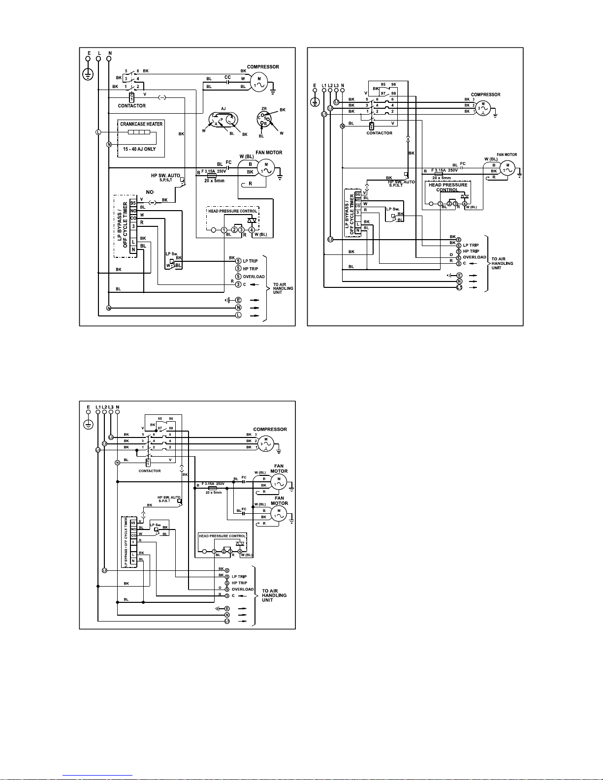
-18-
MCU+ WIRING DIAGRAMS
1 Phase MCU+ 90 3 Phase MCU+ 90 to 100
3 Phase MCU+ 130 to 165
Page 19
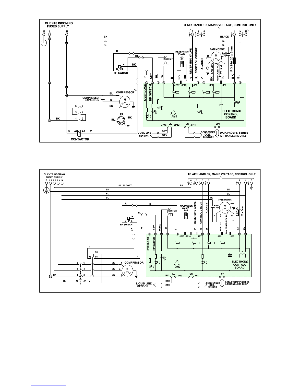
-19-
MHPUE WIRING DIAGRAMS
1 Phase MHPUE 90
3 Phase MHPUE 90
Page 20
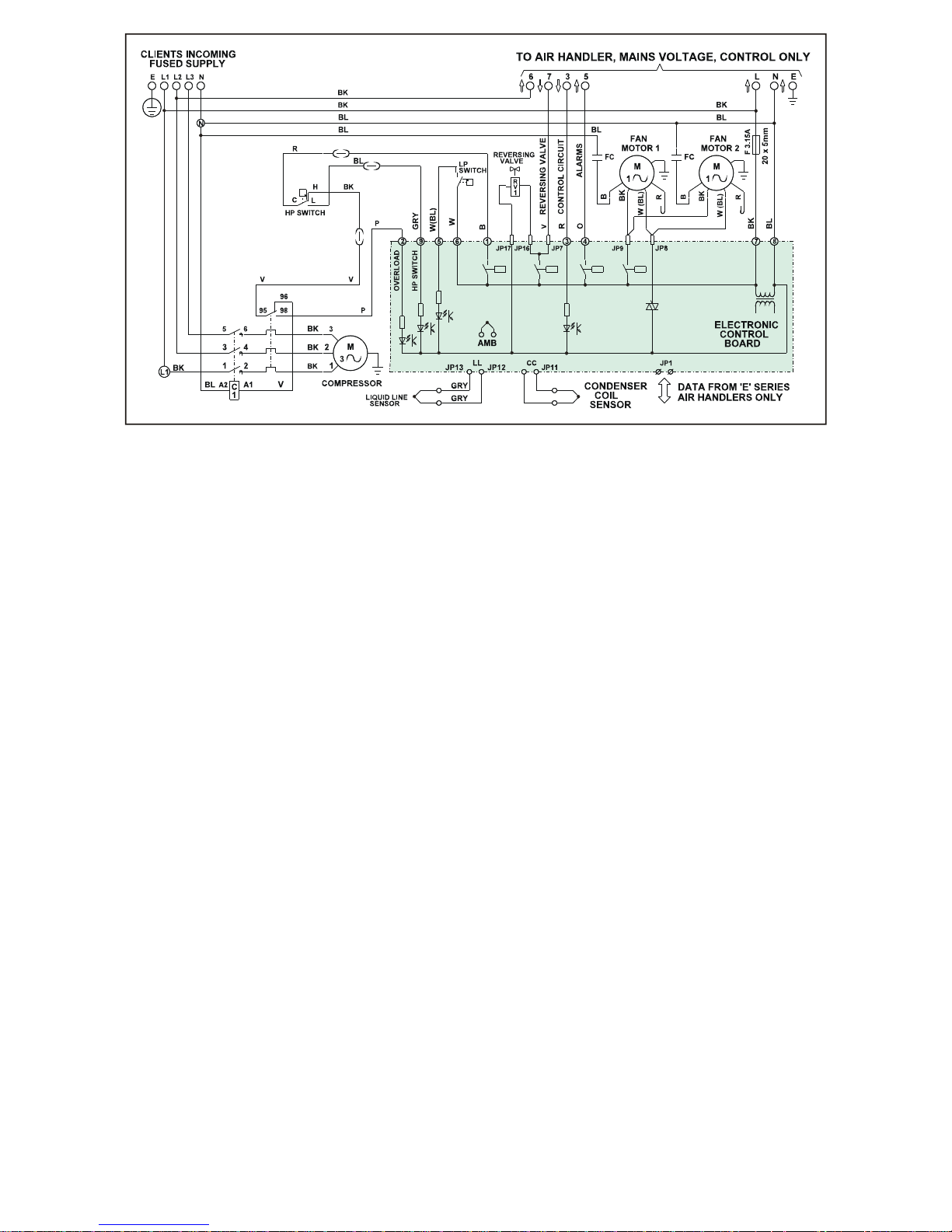
-20-
3 Phase MHPUE 100 to 130
Page 21
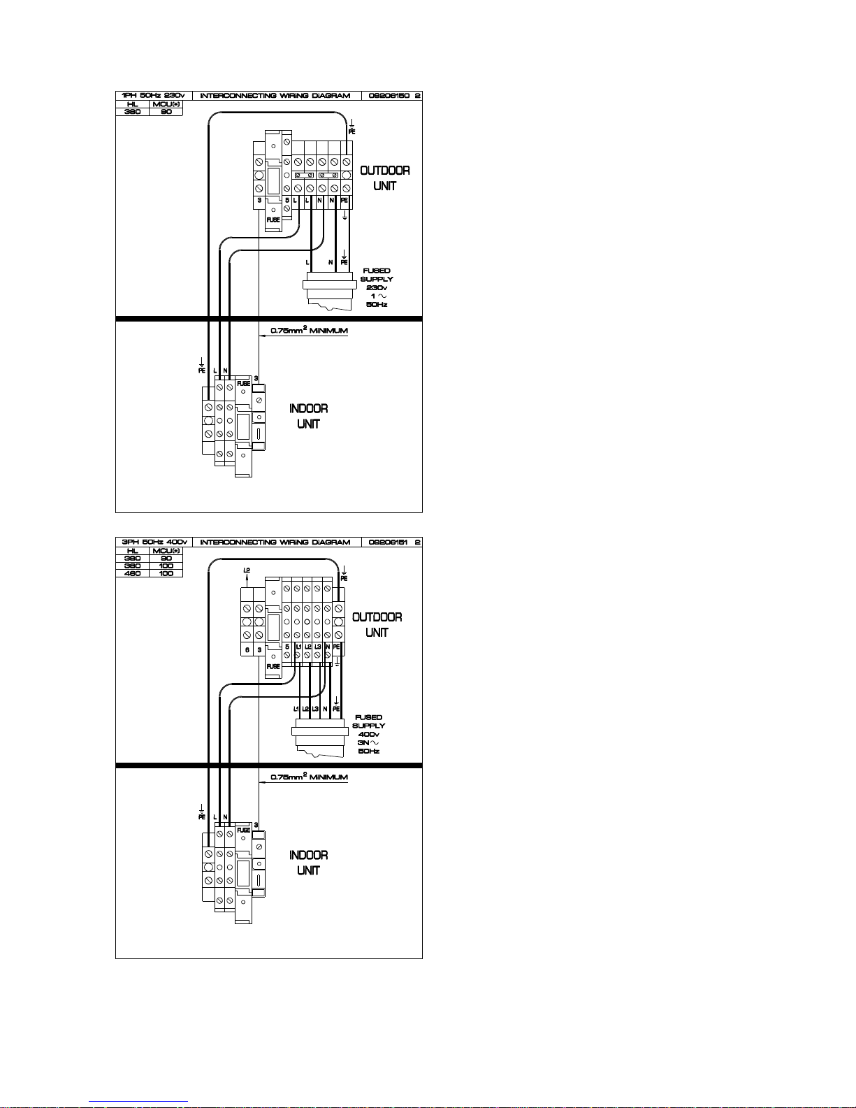
-21-
HL INTERCONNECTING WIRING DIAGRAMS
HL 380 + 1 Phase MCU(+) 90
HL 380 to 460 + 3 Phase MCU(+) 90 to 100
Page 22
-22-
HL 460 to 540 + 3 Phase MCU(+) 130 to 165
HLR INTERCONNECTING WIRING DIAGRAMS
HLR 380 + 1 Phase MCU(+) 90 HLR 380 to 460 + 3 Phase MCU(+) 90 to 100
Page 23
-23-
HLR 380 + 1 Phase MHPUE 90 HLR 380 to 460 + 3 Phase MHPUE 90 to 100
HLR 460 to 540 + 3 Phase MCU(+) 130 to 165 HLR 540 + 3 Phase MHPUE 130
Page 24
-24-
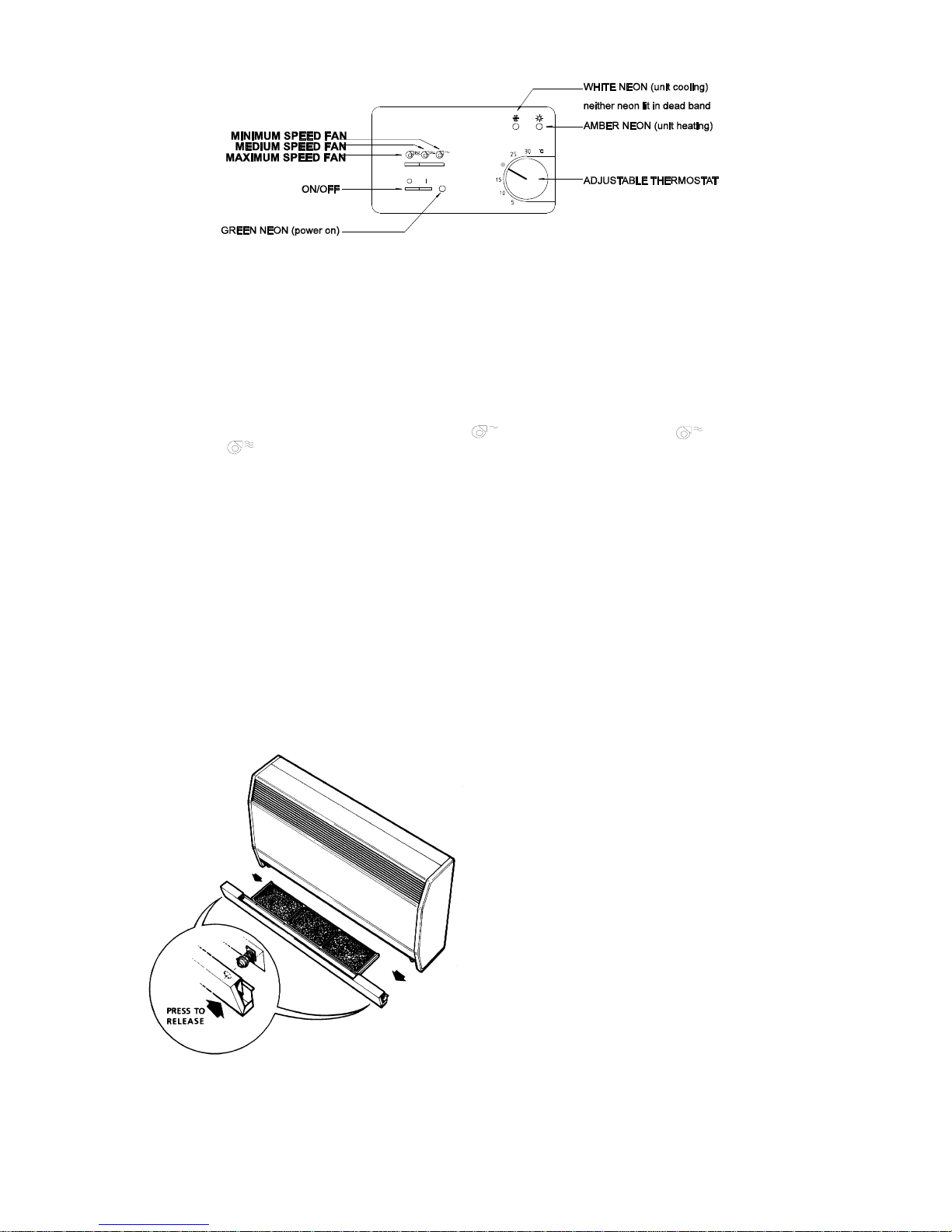
HL OPERATING INSTRUCTIONS (using Speed Selector Switch and Thermostat)
The switches to operate the fan speed and thermostat control are located on the right hand side.
The upper knob selects temperature, which is automatically
controlled by an internal thermostat that senses return room air.
Lower room temperatures can be maintained by turning the knob
clockwise, further towards the snow flake. (Minimum is
approximately 19°C room temperature).
Similarly, higher room temperatures can be maintained by turning
the knob anticlockwise, further towards the sun.
The lower knob selects the fan speed required, or the Off position.
Knob Position
Effect
Upper Lower
Any
Unit Switched Off
As
Set
Minimum fan speed with auto
control for normal room
temperature and lowest sound
level
As
Set
Medium fan speed with auto
control
As
Set
Maximum fan speed giving
rapid change of room
temperature
HLR OPERATING INSTRUCTIONS FOR 97200211 (RCC30)
Page 25
-25-
HLR OPERATING INSTRUCTIONS FOR 96000320 (7204)
REMOTE CONTROLLER
Controls to operate the fan speeds and thermostat are on the front face of the controller.
ON/OFF AND FAN SPEEDS
The switches on the left hand side control the ON/OFF and fan speed operations.
The lower left hand switch is the ON/OFF control. The green neon is lit when the switch is 'ON'.
The upper left hand switch operates the fan speeds.
The fan speed switch gives minimum fan speed at position , medium fan speed at position and maximum fan
speed at position .
TEMPERATURE CONTROL
The right hand knob selects temperature, which is automatically controlled by the thermostat in the remote control
housing; the range is factory set from 17°C to 30°C.
By turning anti-clockwise, lower room temperatures are maintained; by turning clockwise, higher temperatures.
The white neon is lit when the unit is in cooling mode.
The amber neon is lit when the unit is in heating mode (if the system includes a heat pump outdoor unit).
Neither neon is lit when the thermostat is between cooling and heating.
User Maintenance
Isolate at the mains before commencing any maintenance work.
In order to maintain maximum efficiency it is important that the filter behind the return grille is cleaned regularly; this will
normally be every two to three weeks.
SWITCH OFF THE UNIT AND ALLOW THE FAN TO
STOP
Remove the filter from the housing.
Wash the filter (in tepid water) and dry before use.
Alternatively tap the filter gently to remove dust or vacuum
clean.
THE UNIT SHOULD ALWAYS BE USED WITH A
FILTER. FAILURE TO DO SO WILL CAUSE A
DECLINE IN UNIT PERFORMANCE AND MAY
RESULT IN MALFUNCTION.
We recommend that in order to prolong the life and
maintain performance of your 'Marstair' units you arrange
a regular service contract with your TEV Ltd.
installer/dealer.
Page 26
-26-
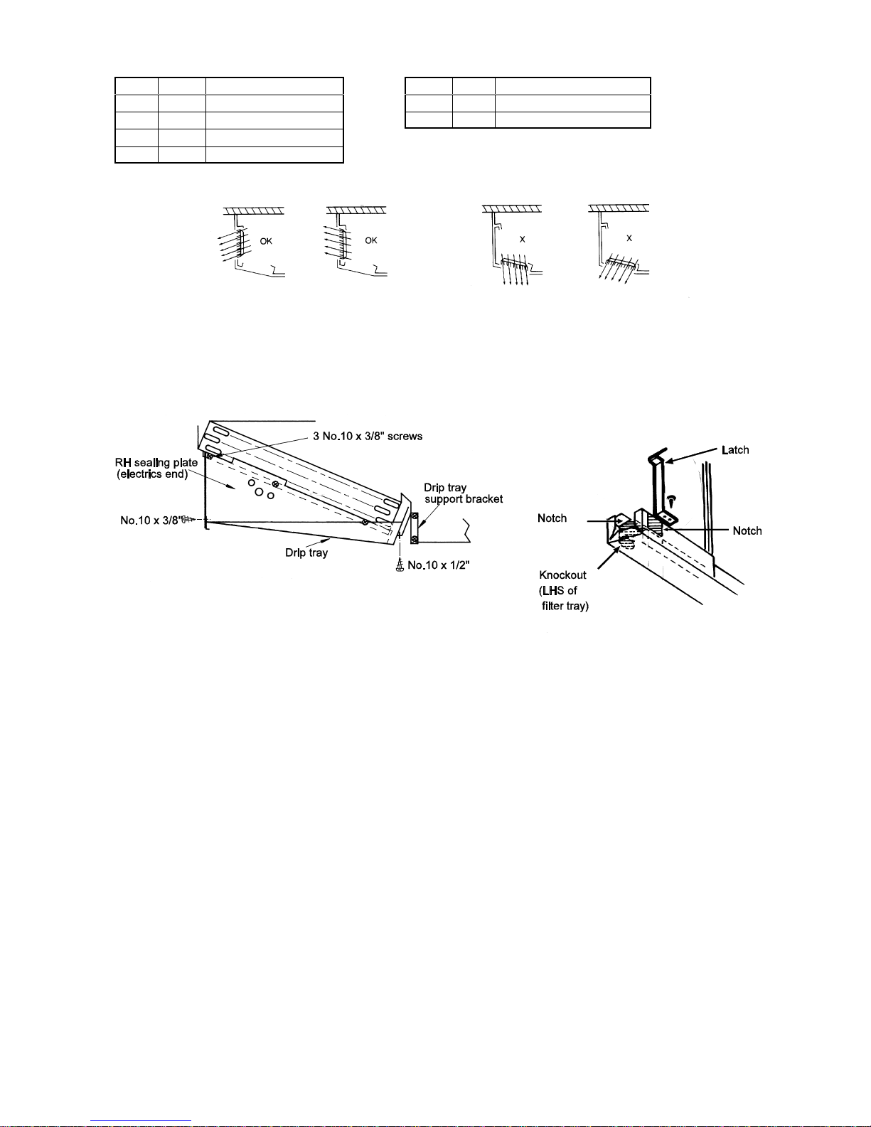
CEILING MOUNTING KITS - 52600230 to 233
This kit converts HL (526) and HLR (527) indoor units for ceiling mounting.
ITEM QTY DESCRIPTION ITEM QTY DESCRIPTION
1 1 Ceiling Mounting Drip Tray 5 1 No. 10 x 1/2" Screw
2 1 Left Hand Sealing Plate 6 1 Sensor Bracket
3 1 Right Hand Sealing Plate
4 2 Latch for Filter Carrier
Ceiling mounted units can only have top discharge on the air off grille.
1 Remove the filter tray, release the fasteners and lift off the cabinet.
2 Remove and keep the 4 off No. 10 x 3/8" screws securing the insulation plate to the sealing plates and the 6 off No.
10 x 3/8" screws securing the sealing plates to the coil. Transfer the six grommets from the old sealing plates to the new
sealing plates.
3 With the black faces of the new sealing plates innermost, secure them to the coil using 6 off No. 10 x 3/8" screws.
Fig. 1.
Fig. 2.
4 Remove the three No. 10 x 3/4" screws from the ends of the drip tray support bracket and extract the plastic drip tray.
5 Secure the indoor unit in position and braze all pipework
6 Fit the drip tray so that the rear flange is held in position by the drip tray support bracket and refit the three No. 10 x 3/4"
drip tray support bracket screws, (Fig. 1).
7 Use two of th e r e t ained No. 10 x 3/8" screws to secure the drip tray to the lugs at the front of the sealing plates. Use
the No. 10 x 1/2" screw provided in the kit to secure the centre of the rear flange to the centre of the drip tray support
bracket, (Fig. 1).
8 If a gravity drain is to be used, pull off the plastic cap from the drain spout, ensure that the drain pipe is kept as low as
possible within the unit and has a constant fall to an open drain. A knockout is provided in the filter tray for cabinet exit.
9 Using four No. 6 x 3/8" screws, secure the two filter carrier retention latches to the rear of the filter carrier, (Fig. 2).
10 Leak test the drip tray and ensure the effectiveness of the gravity drain, (if fitted), before refitting the cabinet; use the
quarter turn fasteners and self tapping screws for additional security. Press the latches towards the filter to fit/release
the filter tray
Page 27
-27-
CONDENSATE PUMP KIT 52600240
This kit is for use on all HL/HLR units for the removal of condensate where gravity drain is not practicable or desirable.
The pump is capable of overcoming a resistance equivalent to 5 metres lift.
The sensor is arranged so that residual condensate in the sump is kept to a minimum.
The kit includes an overflow protection circuit which will prevent further cooling and condensate production if a high
condensate level occurs.
ITEM QTY DESCRIPTION ITEM QTY DESCRIPTION
1 PUMP ASSEMBLY CONSISTING OF: 2 C O N TR O L B O ARD ASSEMBLY
CONSISTING OF:
1Pump
2 Grommet 1 Control Board
2 Hose 4 Mounting Foot
1 Green/Yellow Cable 1 Plastic Cover
1 Bracket
3
4 Cable Tie
1 Connector
4
2 No. 6 Screw
2 Cable Tie
5
1 Sensor Block (with filter)
It is preferable to fit this kit prior to installing the unit; the following
instructions refer to bench fitting.
ISOLATE THE SYSTEM ELECTRICALLY PRIOR TO INSTA LLATION OF
THIS KIT
WALL MOUNTED UNITS
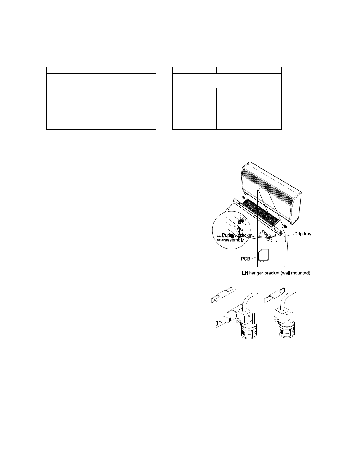
1 Remove the filter tray, release the fasteners and remove the cabinet,
(Fig. 1).
2 Locate and secure the pcb assembly in the left hand hanger bracket,
(Fig. 2).
3 Remove the rubber boots from the black and blue cables running
across the front of the unit and connect to the pcb, black to L, blue to
N.
4 Cut the loop of the red cable (brown on HL u nits) running across the
front of the unit, bare back by 5mm and connect to terminal TB1 on the
pcb.
5 Using 2 x No. 6 screws, supplied loose, secure the pump/bracket
assembly to the left hand hanger bracket at the angle shown in Fig. 2.
Use one of the screws to con nect the earth (green/yellow) cable
ring terminal between the pump bracket and the hanger bracket.
6 Ease off the edge clips and remove the sensor bracket from the drip
tray. The sensor/filter assembly is supplied fitted to a transition bracket.
a If the unit has been supplied with a sensor bracket w ith screws
fitted, align the holes in the transition bracket with those in the
sensor bracket and connect together with the No. 6 screws (Fig.
3a).
b If the unit has been supplied with a sensor bracket with notches
(no screws) fitted, unhook the sensor/filter from the transition
bracket and discard the transition bracket. Hook the sensor/filter to
the unit sensor bracket (Fig. 3b).
Refit the sensor bracket.
7 Push the bottom hose from the pump onto one of the sensor spouts.
8 Connect the red cables from the pump onto the pcb terminals P/L and
P/N. Secure the plastic pcb cover to the red cables.
9 The pump top hose is supplied fitted with a connector suitable for
joining to 8mm bore plastic hose to give condensate outlet. If 1/4"
diameter copper is to be used, the connector should be discarded and
the hose pushed directly onto the copper for at least 20mm, and be
secured with a cable tie.
NOTE: If the condensate outlet pipe bore is less than 8mm and
the outlet is below the level of the sump, syphoning may occur
which will lead to noise on pumping. To ensure quiet running fit
an air break no further than 200mm below the level of the drain
tray by pumping into a larger diameter pip e than that from the
pump.
10 See opposite for application and testing.
Fig. 1.
Fig. 2.
Fig. 3a. Fig. 3b.
Page 28
-28-
CEILING MOUNTED UNITS
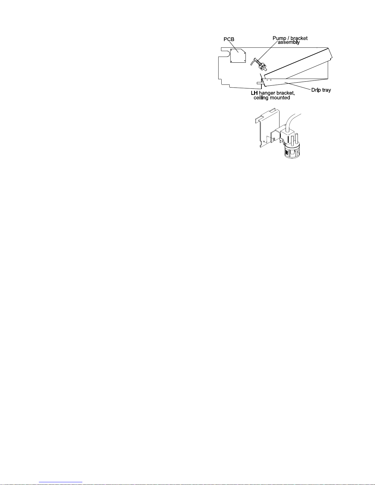
1 Remove the filter tray, release the fasteners and remove the cabinet,
(Fig. 1).
2 Locate and secure the pcb assembly in the left hand hanger bracket,
(Fig. 4).
3 Remove the rubber boots from the black and blue cables running
across the front of the unit and connect to the pcb, black to L, blue to
N.
4 Cut the lo op of the red cable (brown on HL units) running across the
front of the unit, bare back by 5mm and connect to terminal TB1 on the
pcb.
5 Using 2 x No. 6 screws, supplied loose, secure the pump/bracket
assembly to the left hand hanger bracket at the angle shown in Fig. 4.
Use one of the screws to connect the earth (green /yellow) cable
ring terminal between the pump bracket and the hanger bracket.
6 Remov e the sensor bracket from the ceiling mounted drip tray. The
sensor block is supplied fitted to a transition bracket. Hook this bracket
onto the two screws in the sensor bracket and fasten the screw s. Refit
the sensor block to the drip tray.
7 Push the bottom hose from the pump onto the sensor spout.
8 Connect the red cables from the pump onto the pcb terminals P/L and
P/N. Secure the plastic pcb cover to the red cables.
9 The pump top hose is supplied fitted with a connector suitable for
joining to 8mm bore plastic hose to give condensate outlet. If 1/4"
diameter copper is to be used, the connector should be discarded and
the hose pushed directly onto the copper for at least 20mm, and be
secured with a cable tie.
NOTE: If the condensate outlet pipe bore is less than 8mm and
the outlet is below the level of the sump, syphoning may occur
which will lead to noise on pumping. To ensure quiet running fit
an air break no further than 200mm below the level of the drain
tray by pumping into a larger diameter pipe t han that from the
pump.
Fig. 4.
Fig. 5.
TESTING THE PUMP AND CONTROL
a Connect a suitably fused supply to the unit (refer to the unit installation instructions). Allow approximately one
minute for the controls and sensor to stabilize.
b Slowly add water to the condensate tray sump until the pump runs. Initially the pump will be noisy until the air
in the hose has been expelled. It is possible that, on this first cycle, the pump will run dry for a short period
(indicated by noise).
c Add more water to the sump and the pump will cycle in the normal manner.
d With the system in cooling mode, continue adding water to the sump until it reaches the higher of the sensor
probes. The cooling cycle will shut down, and the pump continue to run, until the water has dropped below the
level of this probe.
NOTE: Whenever the electr ical supply to a unit fitted with a condensate pump and controls is interrupted, a delay of
up to 1 minute will occur before the compressor or the pump will start when the supply is reinstated.
TROUBLE SHOOTING
Unit will not cool No mains supply to the control board.
Pump does not run Fuse on control board blown (315 mA x 20mm)
Sensor disconnected from control board
Cooling is interrupted Restriction in pump flow allowing level to rise and trip overflow circuit
Check for blockage or kink in hoses.
Condensate at high level -- tripping overflow circuit
Filter blocked -- remove and clean
Excessive pump noise Air leak in hoses and/or joints
Pumping without water in sump -- control board fault
Loose connection between sensor and control board
Loose fuse, intermittent mains supply to control board.
Debris in pump or bottom hose
Water syphoning due to lack of air break
Application Notes
1 The pump will work against a 5m head. Flow rate is highest with minimum head.
2 Long lengths of drain pipe should not be exposed to the outdoor ambient, otherwise freezing of condensate may occur
during winter operation.
3 It is not advisable to have the outlet of the drain well below the position of the pump, otherwise the syphon effect may
open the pump valves.
4 For normal applications, i.e., where the drain is level or above the pump or within 3 feet below it, no extra check valves
are needed; the pump has its own internal check valves.
5 Ensure that no hose is kinked, as this could seriously affect the pump performance.
Page 29
-29-
LOW PRESSURE HOT WATER COIL KIT
This kit provides LPHW heating for HL (526) and HLR (527) indoor units.
A control valve is not provided in this kit.
Since the coil is upstream of the evaporator, a de-ice thermostat is not necessary on the LPHW coil. It is, however, highly
recommended to fit a de-ice thermostat to the evaporator to protect the LPHW coil.
UNIT SIZE KIT PART NUMBER Item Qty Description
HL/HLR 380 52600227 1 1 LPHW coil assembly
HL/HLR 460 52600226 2 7 Grommet strip
HL/HLR 540 52600224
Fitting the LPHW coil is best done prior to installing the unit.
1 Remove the unit cabinet and lay the unit on its backpanel.
2 Remove the three No. 10 electrics tray retaining screws and spring the tray free.
3 Remove the four No. 10 evaporator coil retaining screws and lift the coil away complete with sealing plates and the
insulation plate.
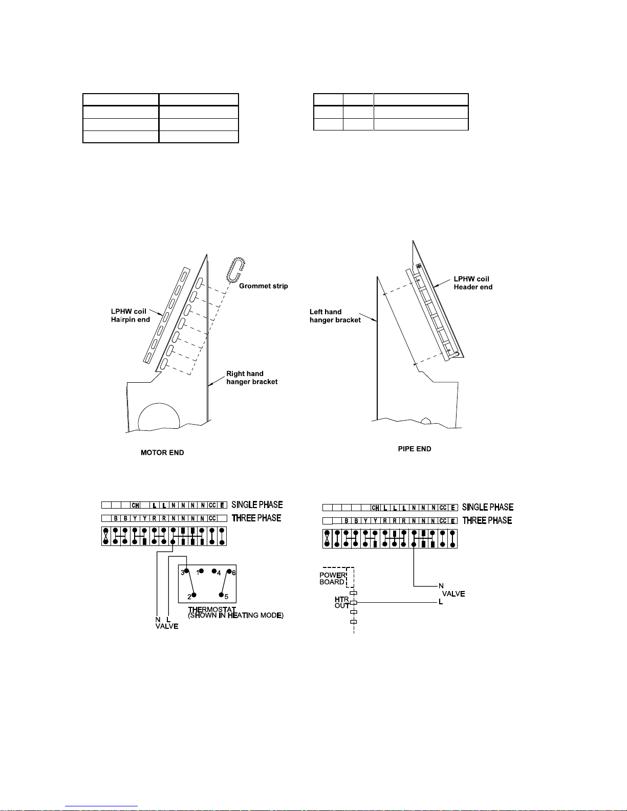
4 Remove and discard the blanking plate from the left hand hanger bracket.
5 Remove the tape covering the slots in the right hand hanger bracket and fit the grommet strips in place, (Fig. 1).
6 Position the end of the LPHW coil into these slots and secure the left hand end plate to the left hand hanger bracket,
(Fig. 2).
Fig. 1. Fig. 2.
7 Replace the evaporator assembly and electrics plate.
8 If a valve is to be fitted, connect to the indoor unit as shown in either Fig. 3, (HL) or Fig. 4, (HLR).
Fig. 3 526 Models Fig. 4 527 Models.
Page 30
-30-
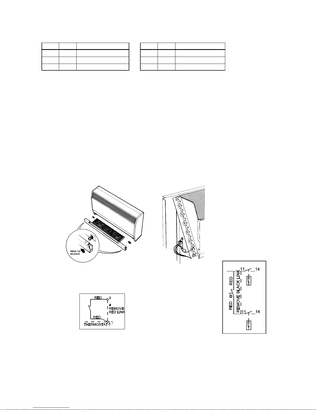
EVAPORATOR DE-ICE THERMOSTAT KIT 52600242
This kit stops the compressor running during cooling mode if the indoor coil starts to ice up, (due to lack of charge, blocked
filter or over condensing).
This kit MUST be fitted to all HL/HLR units w ith LPHW coils fitted, to provide protection against the hot water system freezing.
ITEM QTY DESCRIPTION ITEM QTY DESCRIPTION
1
1 De-ice Thermostat
4
2N
o.
10 x 3/8 Screw
2
1 Mounting Bracket
5
2 Cable Tie
3
1 Red Cable
6
2 Cable Clamp
ISOLATE THE UNIT ELECTRICALLY PRIOR TO INSTALLATION OF THE KIT.
1 Remove the filter tray (Fig. 1), release the cabinet retaining screws and remove the cabinet.
2 Screw the thermostat to the left hand hanger bracket using the 2 x N
o.
10 x 3/8 Screws.
3 Insert the thermostat phial into the hole in the left hand end of the fin block to a depth of at least 150mm; neatly coil the
excess capillary without kinking it.
4 Route the cables along the ledge beneath the drip tray using the self adhesive cable clamps to secure them; pass the
cables through the flexi-grommetted hole into the electrics tray.
5 The cables are supplied to suit HL/HLR 540 models. On all other models, gather the exc ess c able and secure neatly
with a cable tie.
6 For HL units: Refer to Fig. 3. Remove and discard the red cable between the heat/cool thermostat terminal 5 and
the terminal block. Cut the termination off the end of one of the de-ice thermostat cables and bare back
by approximately 10mm to allow it to fit terminal 3. Connect the other cable to the heat/cool thermostat
terminal 5.
7 For HLR units: Refer to Fig. 4. Remove and discard the black cable as indicated. Connect the de-ice thermostat
cables across the vacated terminals.
Fig. 1. Fig. 2.
Fig. 3. Fig. 4.
Page 31
-31-
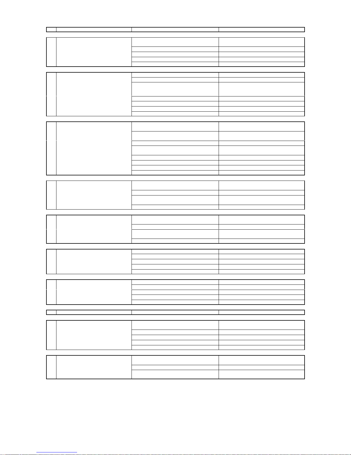
FAULT FINDING
CONDITION POSSIBLE CAUSE ACTION
A Indoor fan motor will not run
No electric supply at socket or switched fuse
box
Check fuse rating and replace if necessary.
Check for loose electrical connections
Unit wiring fault Check wiring and connections
Fan motor capacitor defective Replace if faulty
Fan motor defective Replace if faulty
Internal fuse blown Clear fault and replace fuse
B Inadequate cooling or heating
Dirty evaporator fins/filter Clean if blocked
Evaporator motor not running As in section A
Refrigerant shortage or excess
Check for leaks. Repair, evacuate and
recharge or check for high head pressure and
recover refrigerant if necessary
Faulty thermostat or incorrectly set Replace if faulty
Dirty condenser Clean if necessary
Faulty compressor Replace
LP cutout circuit open (if fitted) Check as refrigerant shortage or excess
C
Compressor and outdoor fan motor
will not run
LP cutout circuit open (if fitted) Check as above
No electric supply at socket or switch fuse box
Check fuse rating and replace if necessary.
Check for loose electrical connection.
Unit wiring fault Check wiring and connections
Capacitor, thermostat, relay or overload
defective
Replace if faulty
Compressor failure Replace if faulty
Controls not set properly Check and rectify
Off cycle delay operating If applicable, wait 3 minutes
High condensate level detected See G
D
System runs for long periods and
will not cycle
Unit underrated for conditioned area Check heat load against capacity
Thermostat not operating correctly Check wiring, position of phial and operation
Refrigerant shortage
Check for leaks. Recover, repair, evacuate
and recharge
Indoor coil dry or partly sweating Dirty condenser Clean fins if necessary
E Indoor coil frosting
Refrigerant shortage
Check for leaks. Recover, repair, evacuate
and recharge
Dirty evaporator fins/filter Clean if blocked
Running in cool ambient without a head
pressure controller
Fit head pressure controller
If room temperature is also low Thermostat set too low or cooling permanentlyReset or replace
F Noisy unit
Fan fouling cowl (outdoor unit) Realign fan
Worn motor bearing Replace motor
Casing or piping vibration Check cause and rectify
Loose parts or mounting Find and tighten
Bent fan blade Replace fan
G Water leaking from unit
Blocked drain Clear obstruction
Units with condensate pump No supply to pump or loose connection Secure the supply
Fouled sensor Clean sensor
Pumping slowly Check drain pipes; if clear, replace pump
Pump windings shorted Replace pump
H Pump always runs
Faulty sensor or pcb Replace sensor or pcb
I
No heating (Heat pump systems
only)
Controls not set for heating Reset
Unit wiring fault Check wiring and connections
Dirty evaporator fins/filter Clean
Faulty thermostat Check for signal; replace if faulty
Reversing valve jammed A light tap may free it; preferably replace
J
Overload tripped on three phase
units
High voltage supply Max rated voltage 254v -- check supply
Compressor failure Replace
Fuses blown
Replace fuses and investigate reason for
fuses blowing
 Loading...