

Page 1

MT80 2D Mini Imager+MTD20 Decoder Baord, Integration Guide, V0.7
MMTT8800
((22DD MMiinnii IImmaaggeerr))
MMTTDD2200
((DDeeccooddeerr BBooaarrdd))
IInntteeggrraattiioonn GGuuiidde
e
Version 0.7 DATE: 2018/11/15
Page 2

MT80 2D Mini Imager+MTD20 Decoder Baord, Integration Guide, V0.7
TABLE OF CONTENTS
11.. IINNTTRROODDUUCCTTIIOONN .................................................................................................................................................................................. 11
11--11.. BBlloocckk DDiiaaggrraamm .................................................................................................................................................................. 11
11--22.. EElleeccttrriicc IInntteerrffaaccee ............................................................................................................................................................ 22
11--22--11.. PPiinn AAssssiiggnnmmeenntt .......................................................................................................................................... 22
22.. SSPPEECCIIFFIICCAATTIIOONNSS .............................................................................................................................................................................. 66
22--11.. IInnttrroodduuccttiioonn ............................................................................................................................................................................ 66
22--22.. TTeecchhnniiccaall SSppeecciiffiiccaattiioonnss .................................................................................................................................. 66
22--33.. IInntteerrffaaccee ........................................................................................................................................................................................ 99
22--33--11.. UUAARRTT IInntteerrffaaccee ............................................................................................................................................ 99
22--33--22.. UUSSBB HHIIDD IInntteerrffaaccee .................................................................................................................................... 99
22--33--33.. UUSSBB VVCCPP IInntteerrffaaccee ................................................................................................................................ 99
22--44.. OOppeerraattiioonn MMeetthhoodd .................................................................................................................................................... 1100
22--55.. MMeecchhaanniiccaall DDiimmeennssiioonn .................................................................................................................................... 1100
22--66.. CCoonnnneeccttoorr SSppeecciiffiiccaattiioonn .............................................................................................................................. 1111
33.. IINNSSTTAALLLLAATTIIOONN .................................................................................................................................................................................. 1122
33--11.. EElleeccttrroossttaattiicc DDiisscchhaarrggee CCaauuttiioonnss .................................................................................................. 1122
33--22.. MMeecchhaanniiccaall DDiimmeennssiioonn .................................................................................................................................... 1122
33--33.. WWiinnddooww MMaatteerriiaallss .................................................................................................................................................... 1133
33--44.. WWiinnddooww SSppeecciiffiiccaattiioonnss .................................................................................................................................... 1144
33--55.. WWiinnddooww CCaarree .................................................................................................................................................................... 1155
44.. RREEGGUULLAATTIIOONNSS .................................................................................................................................................................................. 1155
55.. DDEEVVEELLOOPPMMEENNTT KKIITT .................................................................................................................................................................. 1166
66.. VVEERRSSIIOONN HHIISSTTOORRYY .................................................................................................................................................................... 1177
Page 3
MT80 2D Mini Imager+MTD20 Decoder Baord, Integration Guide, V0.7
___________________________________________________________________________________
1
11.. IINNTTRROODDUUCCTTIIOON
N
The MT80 Mini Imager+MTD20 Decoder Board is designed for 1D Barcode and QR
Code scanning with easy integration. Due to its small size MT80+MTD20 is ideal for
integration into data terminals and other small mobile devices.
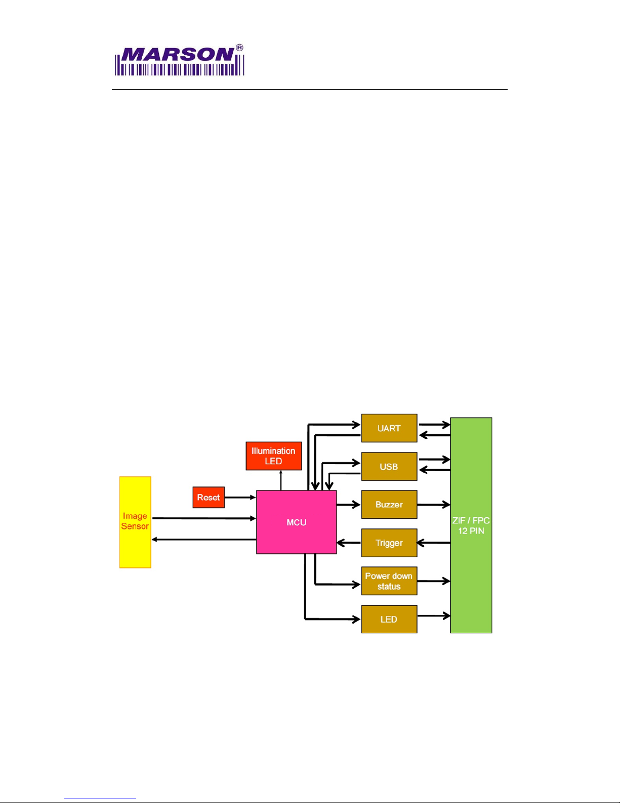
The MT80 Mini Imager consists of 1 illumination LED, 1 aimer LED and a high-quality
image sensor with a microprocessor on MTD20 Decoder Board that contains powerful
firmware to control all aspects of operations and enable communication with the host
system over the standard set of communication interfaces.
Two interfaces, UART & USB, are available. UART interface communicates with the
host system over TTL-level RS232 communication; USB interface emulates a USB
HID Keyboard device and communicates with the host system over USB.
11--11.. BBlloocckk DDiiaaggrraamm
Page 4
MT80 2D Mini Imager+MTD20 Decoder Baord, Integration Guide, V0.7
___________________________________________________________________________________
2
11--22.. EElleeccttrriicc IInntteerrffaaccee
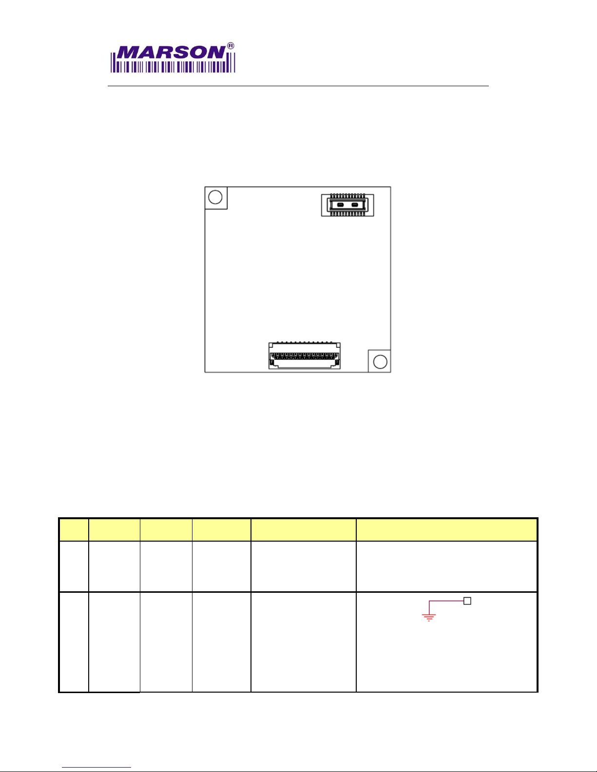
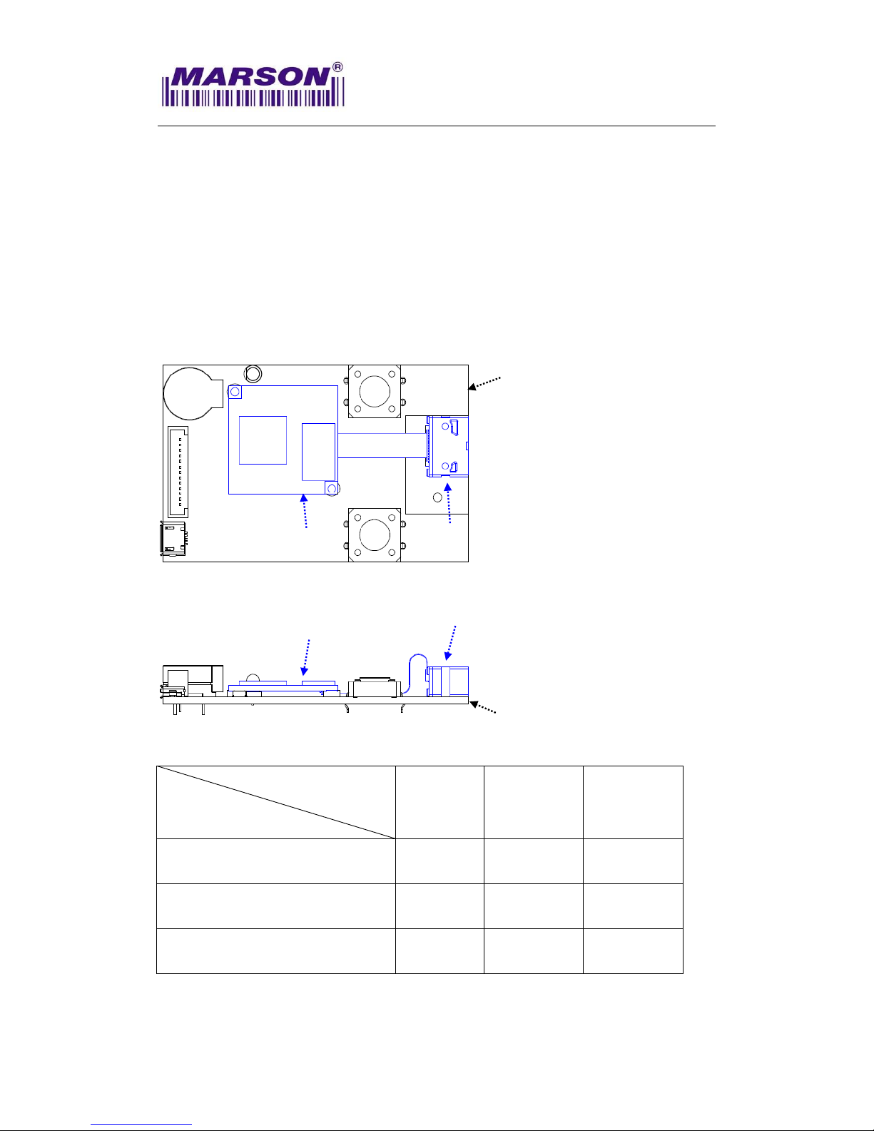
11--22--11.. PPiinn AAssssiiggnnmmeenntt
(Top View of MTD20 Decoder Board)
Pin#
UART
USB
I/O
Description
Schematic Example
1
nPWRDWN
nPWRDWN
Output
When nPWRDWN is
active low, MTD20 is in
sleep mode.
2
GND
GND
------------
Power and signal
ground.
Pin 1
Pin 2
Pin 20
Pin 19
Page 5
MT80 2D Mini Imager+MTD20 Decoder Baord, Integration Guide, V0.7
___________________________________________________________________________________
3
Pin#
UART
USB
I/O
Description
Schematic Example
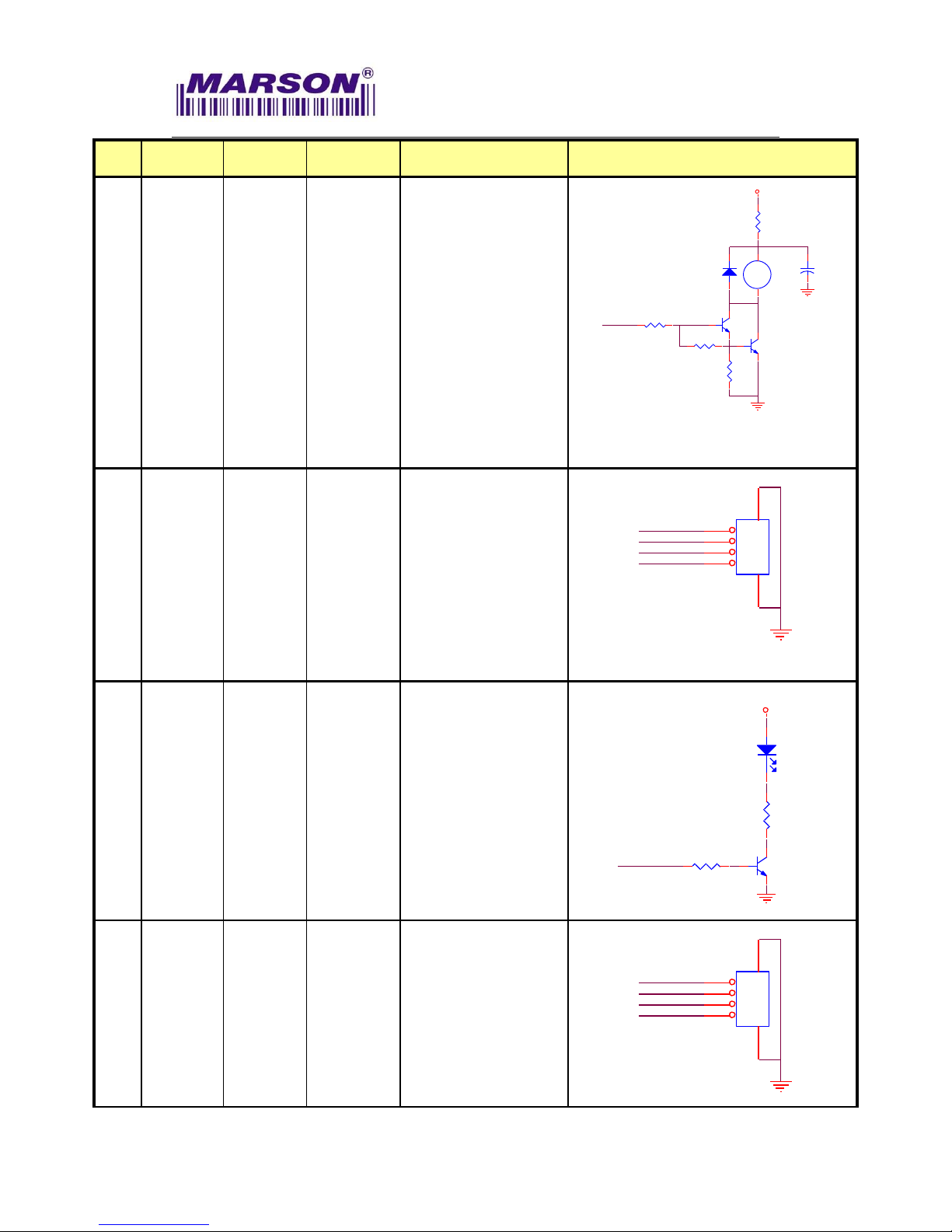
3
Buzzer
PWN
Buzzer
PWN
Output
Active High: it
indicates the status of
Power-Up or a
successful barcode
decoded.
PWM controlled signal
can be used to drive
an external buzzer for
a successful barcode
decoded (Good Read).
R3
10R
Buzzer
Q1
2N3904
Q2
2N3904
R6 2K7
R7 6K8
R8
3K3
BZ
BZ1
BZ_2.7K
2
1
HD1
1N 4148
1
2
+
C8
10uF
+
-
VCC
4
------------
USB_D+
Bidirectional
USB Differential Signal
Transmission
(USB D+)
USB_D+
USB_D-
GND
GND
VIN_5V
USB_Port
4
3
2
1
5
6
5
Good
Read
Good
Read
Output
Active High, it
indicates the status of
Power-Up or a
successful barcode
decoded (Good Read).
LED1
GREEN
1
2
Q4
2N3904
R11
330R
R13 4K7
Decode LED
VCC
6
------------
USB_D-
Bidirectional
USB Differential Signal
Transmission
(USB D-)
USB_D+
USB_D-
GND
GND
VIN_5V
USB_Port
4
3
2
1
5
6
Page 6

MT80 2D Mini Imager+MTD20 Decoder Baord, Integration Guide, V0.7
___________________________________________________________________________________
4
Pin#
UART
USB
I/O
Description
Schematic Example
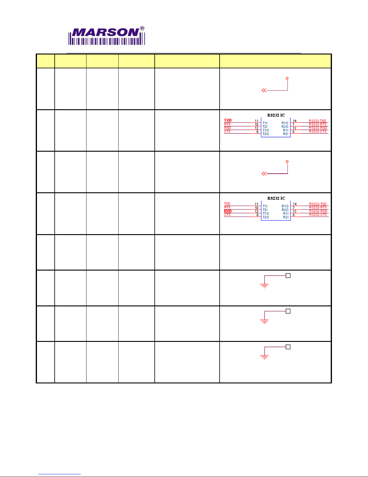
7
nWAKE
nWAKE
Input
When MTD20 is in
sleep mode, active low
to wake up.
8
GND
GND
------------
Power and signal
ground.
9
Trigger
Input
Trigger
Input
Input
High:
Power-up/Standby
Low: Scanning
Operation
*Warning:
1. Pull low at power-up
will prompt the scan
engine into firmware
update mode.
Once trigger is pressed (pull low), scanning
operation continues until a barcode is
successfully decoded or the trigger is released
(pull high). To proceed to the next scanning
operation, release (pull high) first and press (pull
low) the trigger again.
10
RTS
------------
Output
When Handshaking is
enabled, MT80
requests permission
from host to transmit
data on TXD line.
Sipex® Vendor P/N: SP232ACT
11
VDD_3V3_IN
VDD_3V3_IN
------------
Supply voltage input.
Must always be
connected to 3.3V
power supply.
+3V3
12
CTS
------------
Input
When Handshaking is
enabled, host
authorizes MT80 to
transmit data on TXD
line.
Sipex® Vendor P/N: SP232ACT
Page 7
MT80 2D Mini Imager+MTD20 Decoder Baord, Integration Guide, V0.7
___________________________________________________________________________________
5
Pin#
UART
USB
I/O
Description
Schematic Example
13
VDD_3V3_IN
VDD_3V3_IN
------------
Supply voltage input.
Must always be
connected to 3.3V
power supply.
+3V3
14
TXD
------------
Output
UART TTL data output.
Sipex® Vendor P/N: SP232ACT
15
VDD_3V3_IN
VDD_3V3_IN
------------
Supply voltage input.
Must always be
connected to 3.3V
power supply.
+3V3
16
RXD
------------
Input
UART TTL data input.
Sipex® Vendor P/N: SP232ACT
17
IF_SEL
IF_SEL
Input
High: UART
Low: USB
18
GND
GND
------------
Power and signal
ground.
19
GND
GND
------------
Power and signal
ground.
20
GND
GND
------------
Power and signal
ground.
Page 8
MT80 2D Mini Imager+MTD20 Decoder Baord, Integration Guide, V0.7
___________________________________________________________________________________
6
22.. SSPPEECCIIFFIICCAATTIIOONNSS
22--11.. IInnttrroodduuccttiioonn
This chapter provides technical specifications of the MT80+MTD20. Operating
method, scanning range and scan angle are also presented.
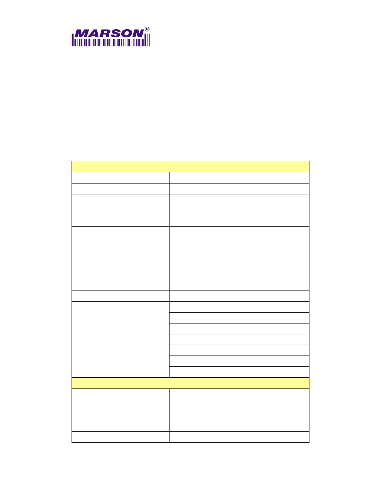
22--22.. TTeecchhnniiccaall SSppeecciiffiiccaattiioonnss
Optic & Performance
Light Source
White LED
Aiming
Red LED dot aimer
Sensor
Area image sensor
Scan Rate
30 frames/ sec
Resolution
5mil/ 0.125mm
Field of View
Horizontal 45°
Vertical 33°
Scan Angle
Pitch Angle ±60°
Skew Angle ±30°
Roll Angle 360°
Print Contrast Ratio
30%
Width of Field
75mm (13Mil Code39)
Depth Of Field
(Environment: 800 lux)
5 Mil Code39: 35 ~ 70mm (4 digits)
10 Mil Code39: 35 ~ 115mm (4 digits)
15 Mil Code39: 45 ~ 165mm (4 digits)
13 Mil UPC/ EAN: 45 ~ 140mm (13 digits)
10 Mil QR Code: 40 ~ 60mm (55 digits)
15 Mil QR Code: 35 ~ 105mm (55 digits)
40 Mil QR Code: 70 ~ 200mm (55 digits)
Physical Characteristics
Dimension
MT80 Imager : W14 x L10 x H7 mm
MTD20 Decoder Board : W25 x L25 x H3.5 mm
Weight
Imager : 1g
Decoder Board : 3.3g
Color
Black
Page 9

MT80 2D Mini Imager+MTD20 Decoder Baord, Integration Guide, V0.7
___________________________________________________________________________________
7
Material
ABS
Connector
Imager to Decoder board : 25pin ZIF
(pitch=0.3mm)
Decoder Board to Host : 20pin Board-to-Board
Connector (pitch=0.4mm)
Cable
Imager to Decoder board : 25 pins flex cable
(pitch=0.3mm)
Electrical
Operation Voltage
3.3VDC ± 5%
Working Current
Typ. 240 mA
Standby Current
Typ. 160 mA
Idle Current
(Sleep Mode)
TBD
Surge Current
< 500 mA
Connectivity
Interface
UART (TTL-level RS232)
USB (HID Keyboard)
USB (Virtual COM)
User Environment
Operating Temperature
0°C ~ 50°C
Storage Temperature
-20°C ~ 60°C
Humidity
0% ~ 95%RH (Non-condensing)
Drop Durability
1.5M
Ambient Light
100,000 Lux (Sunlight)
Page 10

MT80 2D Mini Imager+MTD20 Decoder Baord, Integration Guide, V0.7
___________________________________________________________________________________
8
1D Symbologies
UPC-A/ UPC-E
EAN-8/ EAN-13
Matrix 2 of 5
China Postal Code (Toshiba Code)
Industrial 2 of 5
Interleaved 2 of 5
Standard 2 of 5 (IATA Code)
Codabar
Code 11
Code 32
Standard Code 39
Full ASCII Code 39
Code 93
Code 128
EAN/ UCC 128 (GS1-128)
MSI/ UK Plessey Code
Telepen Code
GS1 Databar
2D Symbologies
QR Code
Regulatory
ESD
Functional after 4KV contact, 8KV air discharge
(It requires housing that is designed for ESD
protection and stray from electric fields.)
EMC
FCC – Part15 Subpart B (Class B)
CE – EN55024, EN55032
Safety Approval
IEC 62471 (Exempt Group)
Environmental
WEEE, RoHS 2.0
Page 11
MT80 2D Mini Imager+MTD20 Decoder Baord, Integration Guide, V0.7
___________________________________________________________________________________
9
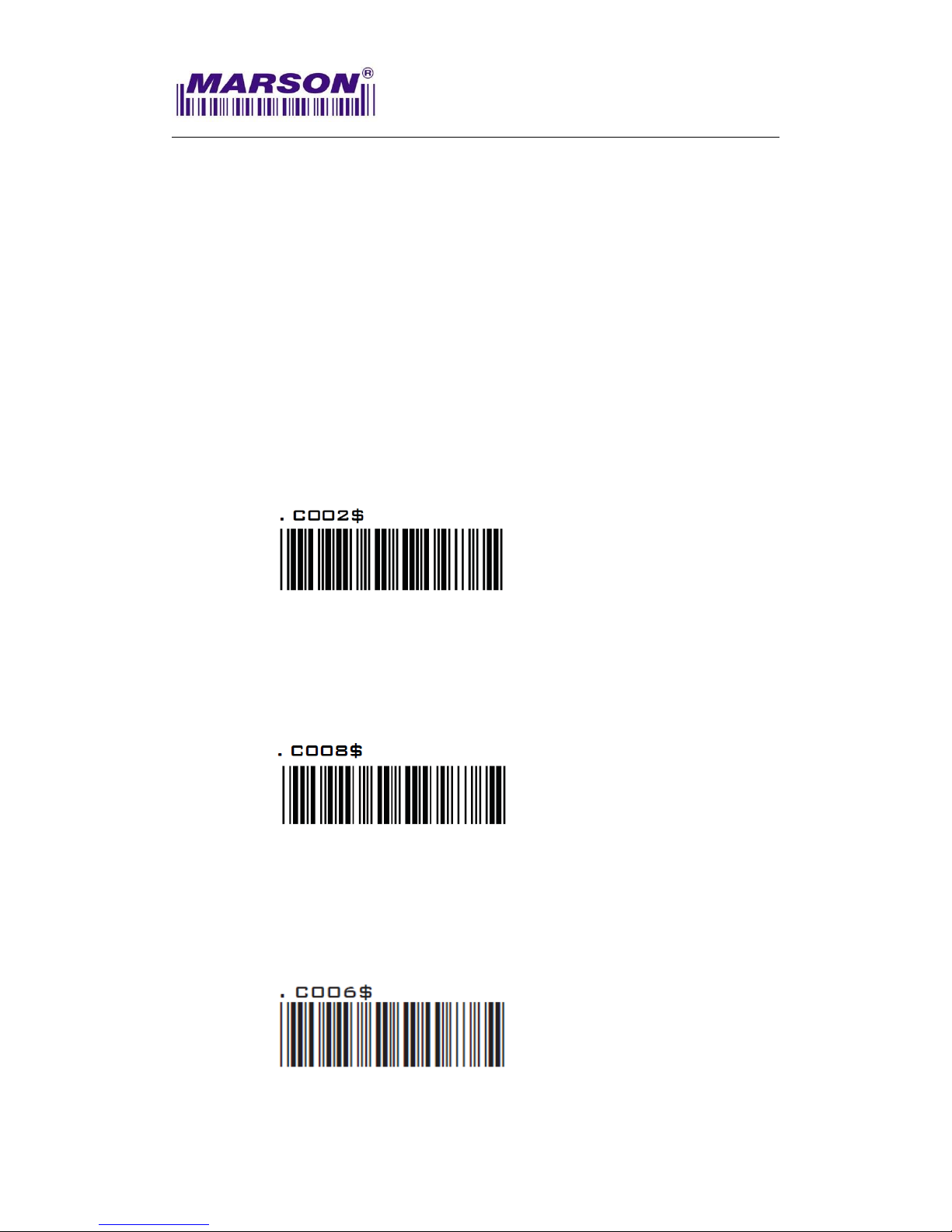
22--33.. IInntteerrffaaccee
22--33--11.. UUAARRTT IInntteerrffaaccee
Below are default communication protocols:
Baud rate: 9600
Data Bits: 8
Parity: None
Stop Bit: 1
Handshaking: None
Flow Control Timeout: None
ACK/NAK: OFF
BCC: OFF
Interface Configuration Barcode:
UART
22--33--22.. UUSSBB HHIIDD IInntteerrffaaccee
Interface Configuration Barcode:
USB HID
22--33--33.. UUSSBB VVCCPP IInntteerrffaaccee
Interface Configuration Barcode:
USB VCP
Page 12

MT80 2D Mini Imager+MTD20 Decoder Baord, Integration Guide, V0.7
___________________________________________________________________________________
10
22--44.. OOppeerraattiioonn MMeetthhoodd
1. At power-up, the MTD20 sends the Power-Up signals over Buzzer and LED
pins as an indication that the MTD20 enters Standby Mode and is ready for
operation.
2. Once the MTD20 triggered by either hardware or software method, MT80 will
emit a beam of light which is aligned with the sensor’s field of view.
3. The area image sensor captures the image of barcode and produces an
analog waveform, which is sampled and analyzed by the decoder firmware
running on the MTD20.
4. Upon a successful barcode decoded, the MT80 turns off the illumination
LEDs, with MTD20 sending the Good Read signals over Buzzer and LED
pins and transmitting the decoded data to the host.
22--55.. MMeecchhaanniiccaall DDiimmeennssiioonn
(Unit = mm)
Imager
Decoder Board
Page 13

MT80 2D Mini Imager+MTD20 Decoder Baord, Integration Guide, V0.7
___________________________________________________________________________________
11
22--66.. CCoonnnneeccttoorr SSppeecciiffiiccaattiioonn
Below is the recommended 20-pin 0.4-pitch board-to-board connector on the host side.
Page 14

MT80 2D Mini Imager+MTD20 Decoder Baord, Integration Guide, V0.7
___________________________________________________________________________________
12
33.. IINNSSTTAALLLLAATTIIOONN
The scan engine is designed specifically for integration into customer's housing for
OEM applications. However, the scan engine’s performance will be adversely affected
or permanently damaged when mounted into an unsuitable enclosure.
Warning: The limited warranty is void if the following recommendations are not
adhered to when mounting the scan engine.
33--11.. EElleeccttrroossttaattiicc DDiisscchhaarrggee CCaauuttiioonnss
All scan engines are shipped in ESD protective packaging due to the sensitive
nature of the exposed electrical components.
1. ALWAYS use grounding wrist straps and a grounded work area when
unpacking and handling the scan engine.
2. Mount the scan engine in a housing that is designed for ESD protection and
stray electric fields.
33--22.. MMeecchhaanniiccaall DDiimmeennssiioonn
When securing the scan engine by utilizing the machine screws:
1. Leave sufficient space to accommodate the maximum size of the scan engine.
2. Do not exceed 1kg-cm (0.86 lb-in) of torque when securing the scan engine to
the host.
3. Use safe ESD practices when handling and mounting the scan engine.
Page 15
MT80 2D Mini Imager+MTD20 Decoder Baord, Integration Guide, V0.7
___________________________________________________________________________________
13
33--33.. WWiinnddooww MMaatteerriiaallss
Following are descriptions of three popular window materials:
1. Poly-methyl Methacrylic (PMMA)
2. Allyl Diglycol Carbonate (ADC)
3. Chemically tempered float glass
Cell Cast Acrylic (ASTM: PMMA)
Cell cast Acrylic, or Poly-methyl Methacrylic is fabricated by casting acrylic
between two precision sheet of glass. This material has very good optical quality,
but is relatively soft and susceptible to attack by chemicals, mechanical stress
and UV light. It is strongly recommended to have acrylic hard-coated with
Polysiloxane to provide abrasion resistance and protection from environmental
factors. Acrylic can be laser-cut into odd shapes and ultrasonically welded.
Cell Cast ADC, Allyl Diglycol Carbonate (ASTM: ADC)
Also known as CR-39TM, ADC, a thermal setting plastic widely used for plastic
eyeglasses, has excellent chemical and environmental resistance. It also has an
inherently moderate surface hardness and therefore does not require
hard-coating. This material cannot be ultrasonically welded.
Chemically Tempered Float Glass
Glass is a hard material which provides excellent scratch and abrasion
resistance. However, un-annealed glass is brittle. Increased flexibility strength
with minimal optical distortion requires chemical tempering. Glass cannot be
ultrasonically welded and is difficult to cut into odd shapes.
Property
Description
Spectral Transmission
85% minimum from 635 to 690 nanometers
Thickness
< 1 mm
Coating
Both sides to be anti-reflection coated to provide 1%
maximum reflectivity from 635 to 690 nanometers at
nominal window tilt angle. An anti-reflection coating can
reduce the light that is reflected back to the host case.
Coatings will comply with the hardness adherence
requirements of MIL-M-13508.
Page 16
MT80 2D Mini Imager+MTD20 Decoder Baord, Integration Guide, V0.7
___________________________________________________________________________________
14
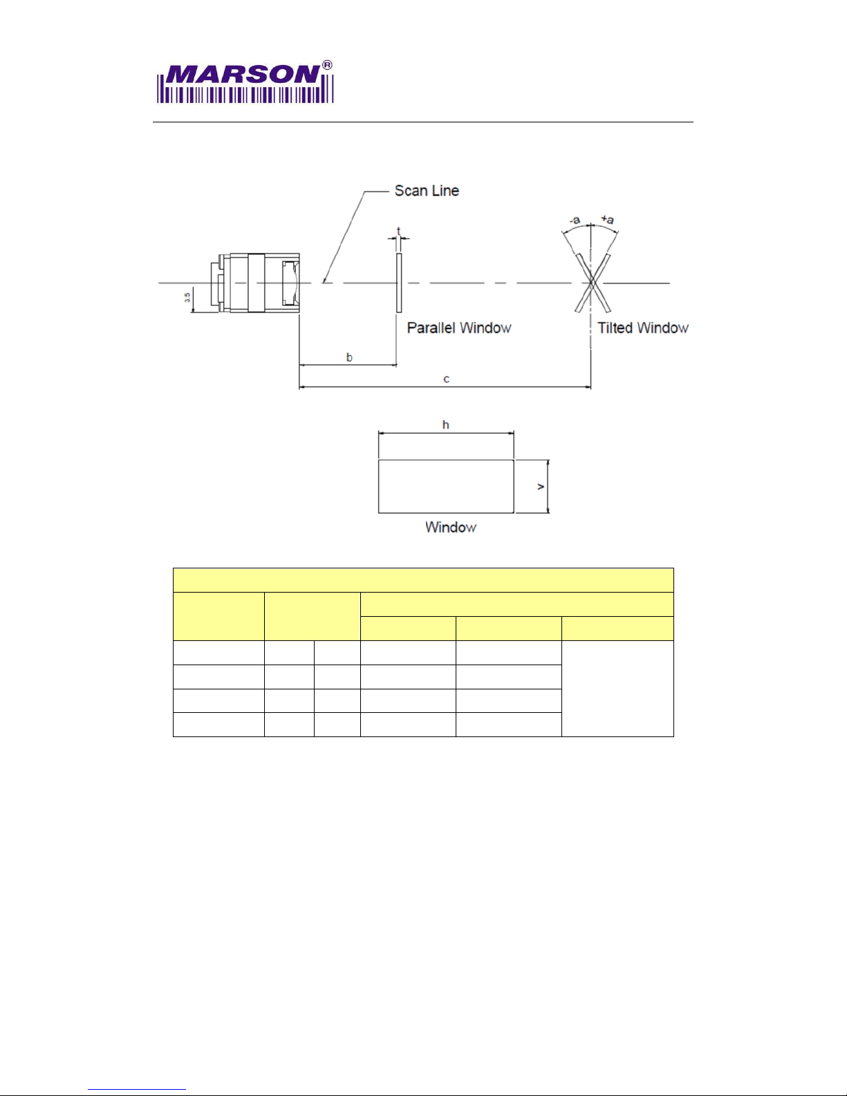
33--44.. WWiinnddooww SSppeecciiffiiccaattiioonnss
Window Specifications for MT80 Integration
Distance
Tilt Angle (a)
Minimum Window Size
Horizontal (h)
Vertical (v)
Thickness (t)
< 0.5 mm (b)
0 0 18 mm
7 mm
< 1 mm
10 mm (c)
> +20°
< -20°
25 mm
15 mm
20 mm (c)
> +17°
< -17°
35 mm
25 mm
30 mm (c)
> +15°
< -15°
50 mm
40 mm
MT80 Imager Side View
Page 17

MT80 2D Mini Imager+MTD20 Decoder Baord, Integration Guide, V0.7
___________________________________________________________________________________
15
33--55.. WWiinnddooww CCaarree
In the aspect of window, the performance of MT80 will be reduced due to any
kind of scratch. Thus, reducing the damage of window, there are few things
have to be noticed.
1. Avoid touching the window as much as possible.
2. When cleaning the window surface, please use non-abrasive cleaning cloth,
and then gently wipe the host window with the cloth that is already sprayed
with glass cleaner.
44.. RREEGGUULLAATTIIOONNSS
The MT80 scan engine conforms to the following regulations:
1. Electromagnetic Compliance – CE EN55022, EN55024
2. Electromagnetic Interference – FCC Part15 Subpart B (Class B)
3. Photobiological Safety – IEC 62471 (Exempt Group)
4. Environmental Regulations – RoHS 2.0, WEEE
Page 18
MT80 2D Mini Imager+MTD20 Decoder Baord, Integration Guide, V0.7
___________________________________________________________________________________
16
55.. DDEEVVEELLOOPPMMEENNTT KKIITT
MARSON MB110 Demo Kit (P/N: 11B0-A020000) enables the development of products
and systems using the MT80+MTD20 on the MS Windows OS platform. Besides the
Multi I/O board (P/N: 21B0-204A000), the MB110 Demo Kit also provides the software
and hardware tools required for testing the MT80+MTD20 applications before
integrating it into the host device. Please contact your sales representative for
ordering information.
MB110 Multi I/O Board (P/N: 21B0-204A000)
MB110 Demo Kit Accessories O: Supported X : Not Supported
Interface
Cable
RS232
(UART)
USB HID
USB VCP
External Y-cable
o o o
(P/N: 7090-1583A00)
Internal Y-cable
o o o
(P/N: 5300-1315X00)
Micro USB Cable
x o o
(P/N: 7005-9892A50)
MB110 Multi I/O Board
MTD20
MT80
MTD20
MT80
MB110 Multi I/O Board
Page 19

MT80 2D Mini Imager+MTD20 Decoder Baord, Integration Guide, V0.7
___________________________________________________________________________________
17
66.. VVEERRSSIIOONN HHIISSTTOORRYY
Rev.
Date
Description
Issued
Checked
0.1
2017.11.24
Preliminary Draft Release
Shaw
Kenji & Hus
0.2
2018.01.10
Updated Chapter 5
Shaw
Kenji
0.3
2018.03.14
Updated VCC in Chapter
1-2-1
Shaw
Kenji
0.4
2018.06.27
Defined MT80 as 2D Mini
Imager
Defined MD200 as Decoder
Board
Updated Chapter 1-2-1
Updated Chapter 5
Shaw
Kenji
0.5
2018.07.04
Updated Chapter 2-5
Revised MTD20 DIM to
25x25x3.5mm
Updated Chapter 5, adding
MB110
Shaw
Hus
0.6
2018.09.03
Updated Chapter 3-4
Shaw
Hus
0.7
2018.11.15
Renamed MD200 to
MTD20
Removed 20Mil Code39 &
13Mil QR Code DOF
Shaw
Kenji
Marson Technology Co., Ltd.
9F., 108-3, Mincyuan Rd., Sindian Dist., New Taipei City, Taiwan
TEL: 886-2-2218-1633
FAX: 886-2-2218-6638
E-mail: info@marson.com.tw
Web: www.marsontech.com
 Loading...