

Page 1

e-Tracker Portable Energy Monitor
Operating &
maintenance manual
Page 2
Marshall-Tufflex Energy Management manufacture a range of products to help
organisations save energy, reduce costs and lower carbon emissions.
The Sinergy range of fixed and portable metering units identify exactly where and how
your energy is being used which then helps pinpoint potential waste and ultimately
cost saving.
Sinergy is a well established in the sub metering market and was brought into the
Marshall-Tufflex Energy Management group in 2010.
Marshall-Tufflex Ltd is a market leader in the electrical industry and has been trading
for over 70 years and includes a wide portfolio of Cable Management and Energy
Management product solutions.
The group is a BS EN ISO 9001:2008 assessed company and also holds BS EN ISO
14001:2004 environmental standard and also we received an excellent rating on our
energy management from The Carbon Trust in 2007.
Introduction to Marshall-Tufflex Energy Management
Page
What is e-Tracker? 3
Kit contents 3
What does e-Tracker measure? 3
Installation and set up 4
e-Tracker set up prompts and controls 6-7
Error messages 8-9
e-Tracker operational specification 10
Memory span 10
CT selection 11
Deltrax5 software guidelines 11-17
Trouble shooting 17-18
Ensure that safe working conditions are in place in all potentially hazardous
environments. The e-tracker unit must be installed by a competent person using the
e-tracker installation instructions or Operating & Maintenance Manual.
Contents
Safety information
Page 3
e-Tracker portable energy monitor operating and maintenance manual
3
Features:
Mains or 16 day battery operation*
Magnetic back for easy mounting
Multiple memory locations
Pulse input
Optional voltage connections
CT amps range indicator
Clip-on CTs for fast safe instalation
EV-Trac electrostatic phase identifier
Optical or magnetic gas meter reader
available
Deltrax5 software is Windows 7
compatible
The e-Tracker also displays average and peak demand to enable the calculation of load
factor. Deltrax5 software highlights demand excursions and potential unauthorised
consumption.
*In battery only operation the e-Tracker will only give accurate current measurements, all other readings will be assumed.
e-Tracker is a portable kWh meter which monitors the incoming power
supply to show the pattern of demand over an hour, day, week or month.
As e-Tracker is portable you have the flexibility to use it for measuring
sub-circuits and other specific equipment without the need to have a
fixed sub-metering solution.
What is e-Tracker?
Sold as a full kit comprising:
e-Tracker with integral EV-Trac
1Ø -3Ø voltage reference converter
Set of 3 F30-1000 dual range
Flexeclamp CTs 30cm - 1000Amps
/200Amps
How is data collected?
e-Tracker records and stores all data, which is then downloadable via USB memory stick
into our Deltrax5 software. This data is graphically displayed on a monthly, weekly or
daily basis or alternatively processed in Excel format.
Kit contents
Voltage
Current
kW
kVA
Power factor
kVAR
kWh
KVArH
Average and peak demand
What does e-Tracker measure?
Set of 3 fused volt clips
Single phase lead, EV-Trac phase
identity probe
Deltrax5 data analysis software
1 USB memory stick
Carry case
Page 4
Installation and set up
Isolate any accessible un-insulated conductors during installation. Clip
CTs to all appropriate cables/conductors with all arrows facing the load.
All transducers including voltage reference inputs (if used) should be
fitted and connected to e-Tracker before e-Tracker is switched on.
Practical and accurate connection options for single and 3 phase use:
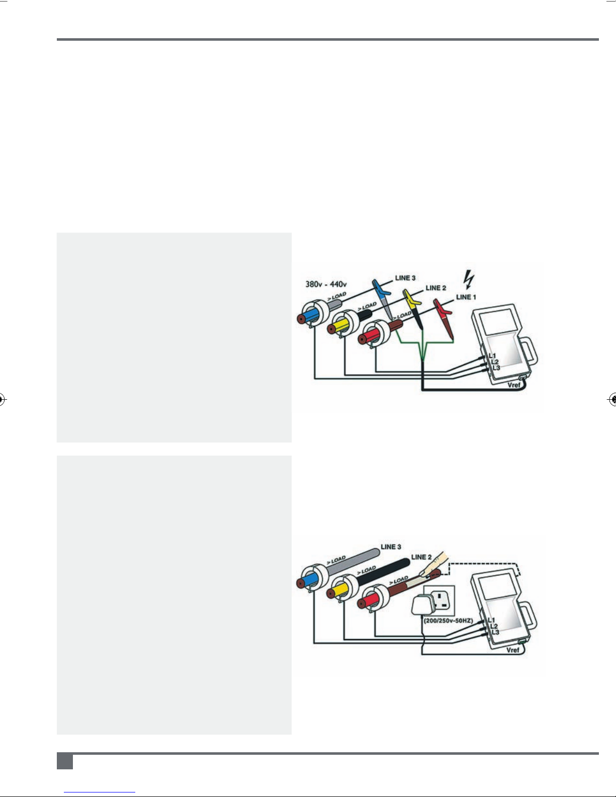
Use e-Tracker with its fused voltage clips
for maximum accuracy on all parameters
3Ø direct voltage measurement
The set of colour coded fused voltage crocodile
clips must be securely attached to pick up the
phase voltages with the colours matching the
attached CTs.
Red/Brown = Line 1
Yellow/Black = Line 2
Blue/Grey = Line 3
No neutral connection is required although e-Tracker
can be earthed Green/Yellow lea
connection ensures high accuracy recording.
d. Direct voltage
EV-Trac 3 phase volt reference conversion
from a single phase socket outlet
3Ø EV-Trac voltage pickup
e-Tracker’s internal 1Ø- 3Ø converter is automatically
applied when three CTs are connected to cables with
voltage reference taken from a 1Ø source all supplied
from the same distribution transformer.
Diagram 1
Diagram 2
Follow standard
safety procedure
Finger held probe
included to identify
phase on low load
Battery on
permanent
charge via
socket
(The CTs require sufficient primary current to be able to
detect zero crossover see diagram 7 on page 9
Should automatic identification fail the EV-Trac
electrostatic probe may be used. Please note this can
only be effective on un-armoured phase cables.
e-Tracker calculates the three equivalent Line-Line
voltage vectors and assigns them to the correct
phases.
EV-Trac offers a safe alternative when direct voltage
connection is not practical, kW/kWh accuracy is good
particularly when phase voltage amplitud
4
e-Tracker portable energy monitor operating and maintenance manual
)
For single phase use CT1 and 13A plug
es are similar.
Page 5
5
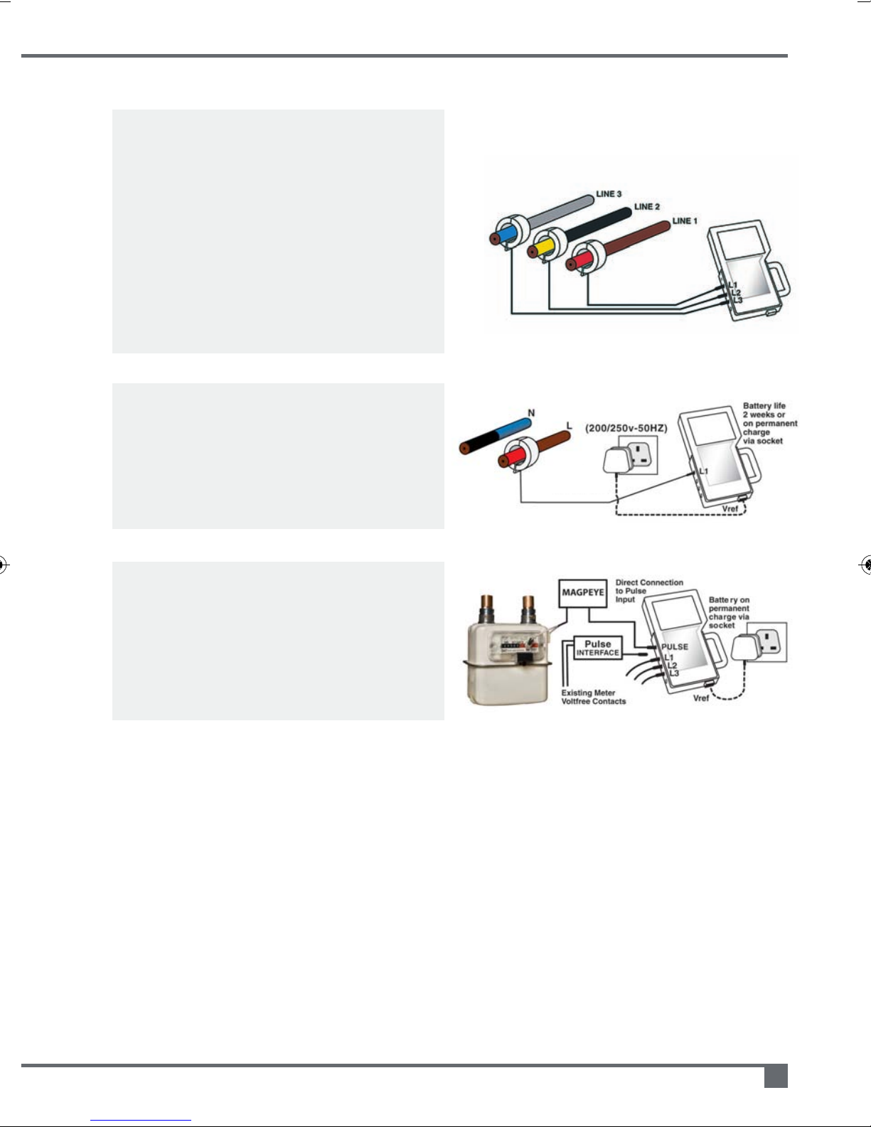
Diagram 3
Basic recordings of demand
profiles and phase balance
2+ weeks
battery life
Diagram 4
Diagram 5
Battery only operation measuring current
and calculated kVA demand profiles
3Ø current recording
This simple method is often very adequate for
determining day/night consumptions patterns,
demand peaks, phase balance and calculating
kVAh totals. In this mode e-Tracker operates
totally from its battery only and has an adjustable
nominal voltage (default setting 415V).
e-Tracker will produce line current profiles and
derive kVA profiles.
Single phase recording
Single phase with the voltage reference derived
from a wall socket etc. Alternatively Tracker will
record current for up to 2 weeks on battery only.
In battery mode Tracker has an adjustable
nominal voltage (default setting 240v.)
Pulse count input (minimum integration period 1 min)
When using the optional pulse input interface,
Tracker can accept a volt free contact closure
from any suitable gas, water or electric metre.
Alternatively the Magpeye optical metre reader
may be connected. Normal analogue inputs are
usable at the same time as pulse input.
Page 6
e-Tracker portable energy monitor operating and maintenance manual
6
e-Tracker set up prompts and controls
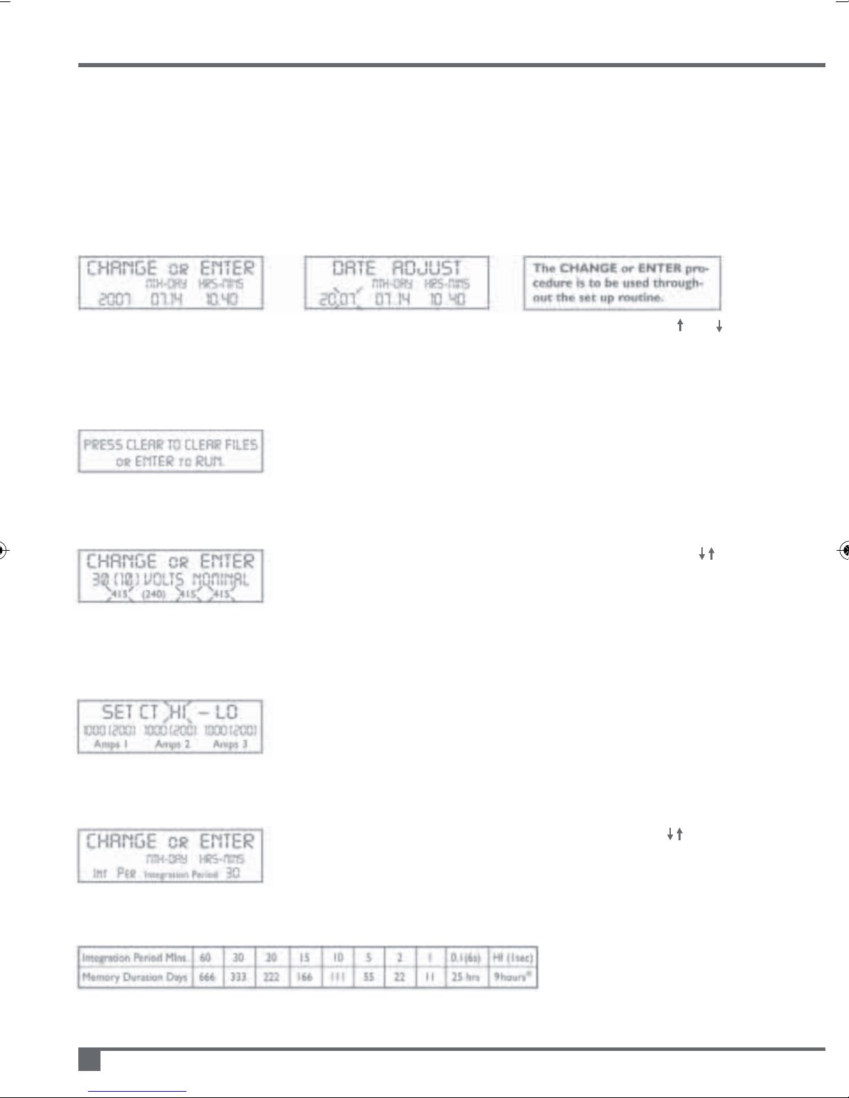
1) Time and date adjustment
If date and time correct press ENTER Alter flashing character(s) using CHANGE and
Press CHANGE to alter any number if required press ENTER to continue and proceed to 2)
2) Memory refresh and/or continue set up
If all data has been downloaded or is redundant press CLEAR &
CHANGE to alter ‘NO’ to ‘YES’.
Press ENTER to confirm memory refresh and continue to 3)
3) Voltage range auto set
For diagrams 3 & 4 on page 5 (battery only use) press CHANGE to
alter default value. Choose a nominal value (default +/-10%). Press
ENTER to continue to 4).
NB: Recorded kVA(h) accuracy dependent on variance of service
voltage, PF defaulted to unity.
4) CT HI/LO range selection
Press ENTER to accept the high range (normally 1000Amp) or press
CHANGE to select LO (200Amps i.e. 20% of HI range)
Press ENTER to continue to 5).
5) Integration period adjust
Press ENTER to accept displayed value or press CHANGE to
select periods of 60, 30, 20, 15, 10, 5, 2, 1 minutes, 6 seconds (0.1), 1
second (HI) integration*
Press ENTER to select and continue to 6)
Memory span
(duration related to aggregate total of 5 memory files)
*V
1
, V2, V3, I1, I2, I3only recorded
for 1 second integration
Once the e-Tracker has been installed slide BATTERY SUPPLY switch ON.
The display will show SELF TEST followed by:
Page 7
7
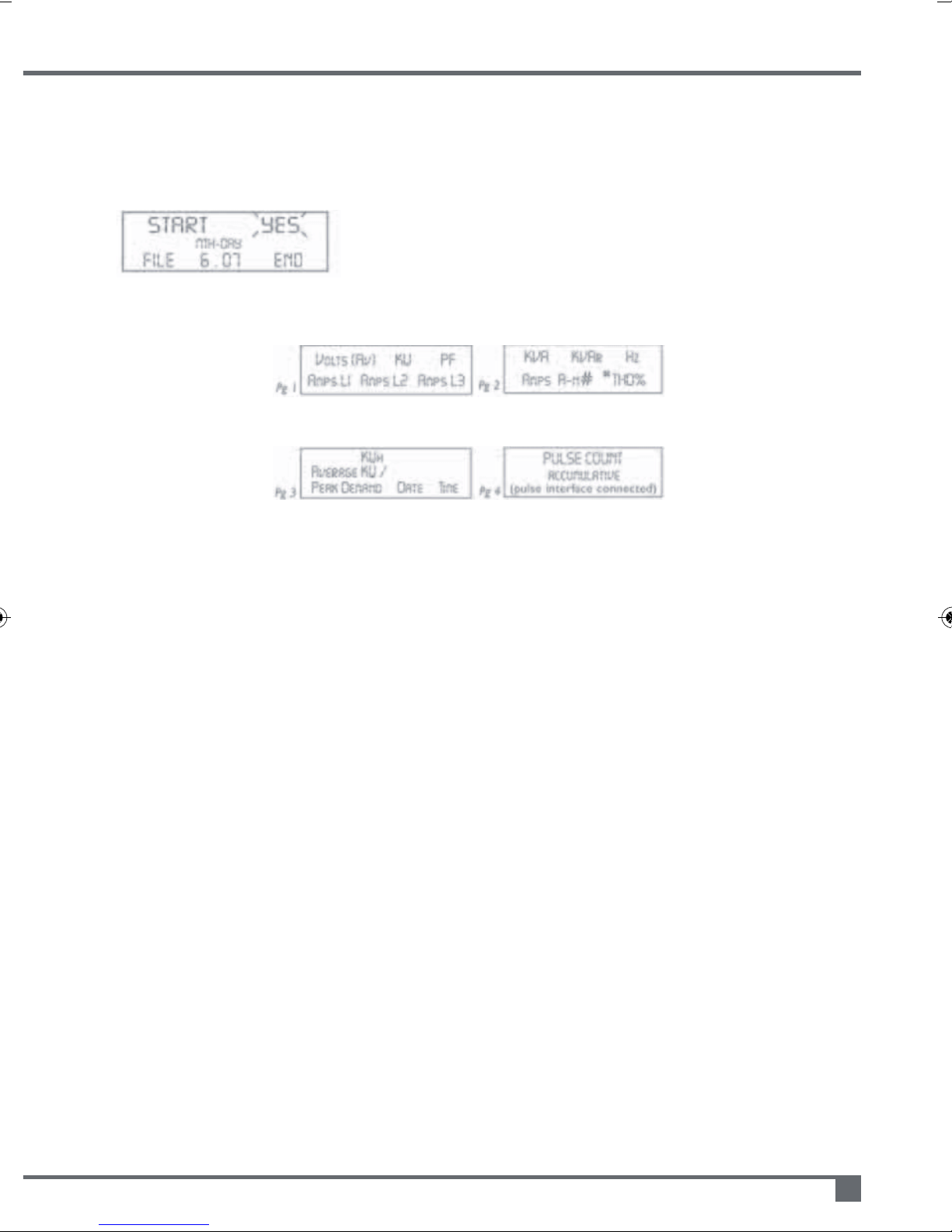
6) Start recording
If memory is full or all of the 5 files are used, CLEAR is displayed,
change NO to YES and press ENTER. Otherwise a FILE END
message will indicate the duration of memory available. If duration is
insufficient for the next test press CHANGE, press CLEAR to revert to
2) then refresh memory.
If memory duration is OK press ENTER.
7) Stop recording
Press STOP TEST at the end of a recording exercise and press ENTER to confirm. All data will be
retained until a Clear Memory function is performed. e-Tracker will stop automatically when memory is
full, it will not roll on. Recording will stop if the battery supply is switched off. It is always
recommended to use STOP TEST button.
8) Switching off
Before switching the e-Tracker off, ensure that you stop recording, please refer to 7).
Slide battery supply switch to OFF at all times when the unit is not to be used. All recorded data
remains in memory until cleared, please see 2).
NB: Always wait 5 seconds after switching off before switching back on.
9) Downloading e-Tracker to USB memory stick
With USB memory stick fitted and e-Tracker switched on, hold down START button until green LED is
illuminated. It will then flash to indicate data processing. 'Serial out' will also appear on display while
data is buffered prior to loading on USB memory stick.
Only remove USB memory stick when green LED is permanently off.
NB: Loading may take many minutes if recording period is extensive or on short integration.
ERROR INDICATION – Red LED sequences:
1) Slow flash for 10 seconds – an error has been detected
2) Permanently on for 10 seconds – non compatible or no USB memory stick fitted
3) Fast flash – insufficient space remaining on USB memory stick
4) Intermittent flash 3xon – off – 3xon – no recorded data in e-Tracker files.
When the
recording/test is
started the e-Tracker
displays Pgs 1 – 3 (4).
Page change
Advances the display
to Pg2, 3 (& 4). AUTO
scrolls pages until
Page is pressed.
Notes Pg2
#Vectoriallycalculatedvalueof
neutralcurrentA-n
*Displayedvalueofcalculated
THDto5thharmonic(not
recordedinmemory)Pg2only
Notes Pg3
Peakdemandandthetimeand
dateoccurred
Page 8
5)
(2 messages flashing)
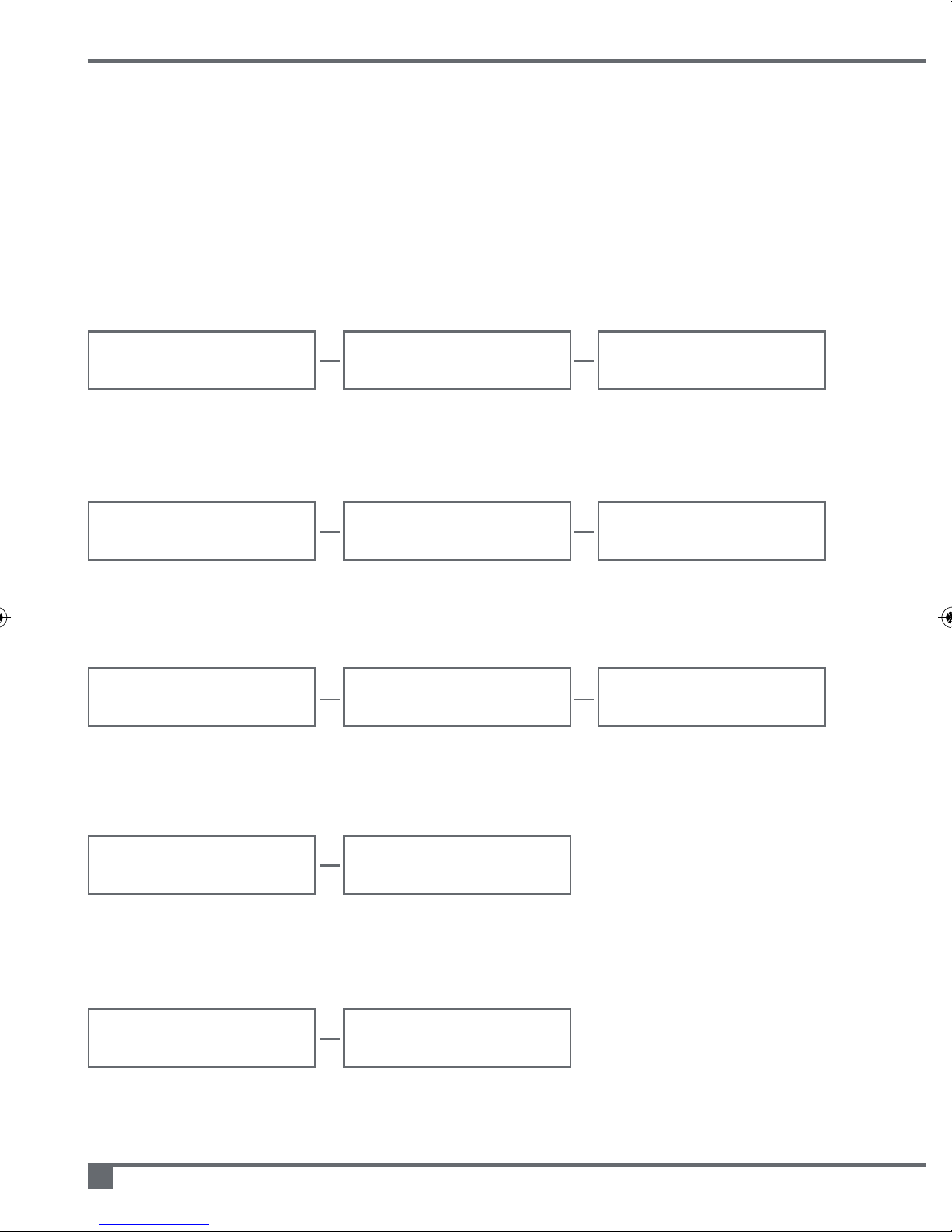
CTs wrong way round or CTs not in l1 connector when used on single phase
4)
(2 messages flashing)
Two CT connected to same phase
e-Tracker portable energy monitor operating and maintenance manual
8
Error messages
After switch on and during the set up the display will indicate an unacceptable connection.
Check CTs and voltage reference input (if used), correct any error, press ENTER and
proceed with set-up.
1)
(3 messages flashing)
No CTs connected
--
ERROR
--
TRANSDUCER
--
NO CT
--
MTH-DAY HRS-MINS
2011 07.14 10.40
--
ERROR
--
MTH-DAY HRS-MINS
2011 07.14 10.40
TRANSDUCER
MTH-DAY HRS-MINS
2011 07.14 10.40
--
CT1-2-3 ODD
--
MTH-DAY HRS-MINS
2011 07.14 10.40
2)
(3 messages flashing)
CTs have different full scale current ratings or only two are connected
--
ERROR
--
MTH-DAY HRS-MINS
2011 07.14 10.40
TRANSDUCER
MTH-DAY HRS-MINS
2011 07.14 10.40
VOLTS--CT ODD
--
MTH-DAY HRS-MINS
2011 07.14 10.40
3)
(3 messages flashing)
If three phase volt probes connected but only one CT connected VOLTS CT ODD
--
ID ERR 1
--
MTH-DAY HRS-MINS
2011 07.14 10.40
--
NOT 3 PHASE
--
MTH-DAY HRS-MINS
2011 07.14 10.40
--
ID ERR 2
--
MTH-DAY HRS-MINS
2011 07.14 10.40
--
CTS ODD
--
MTH-DAY HRS-MINS
2011 07.14 10.40
Page 9
7)
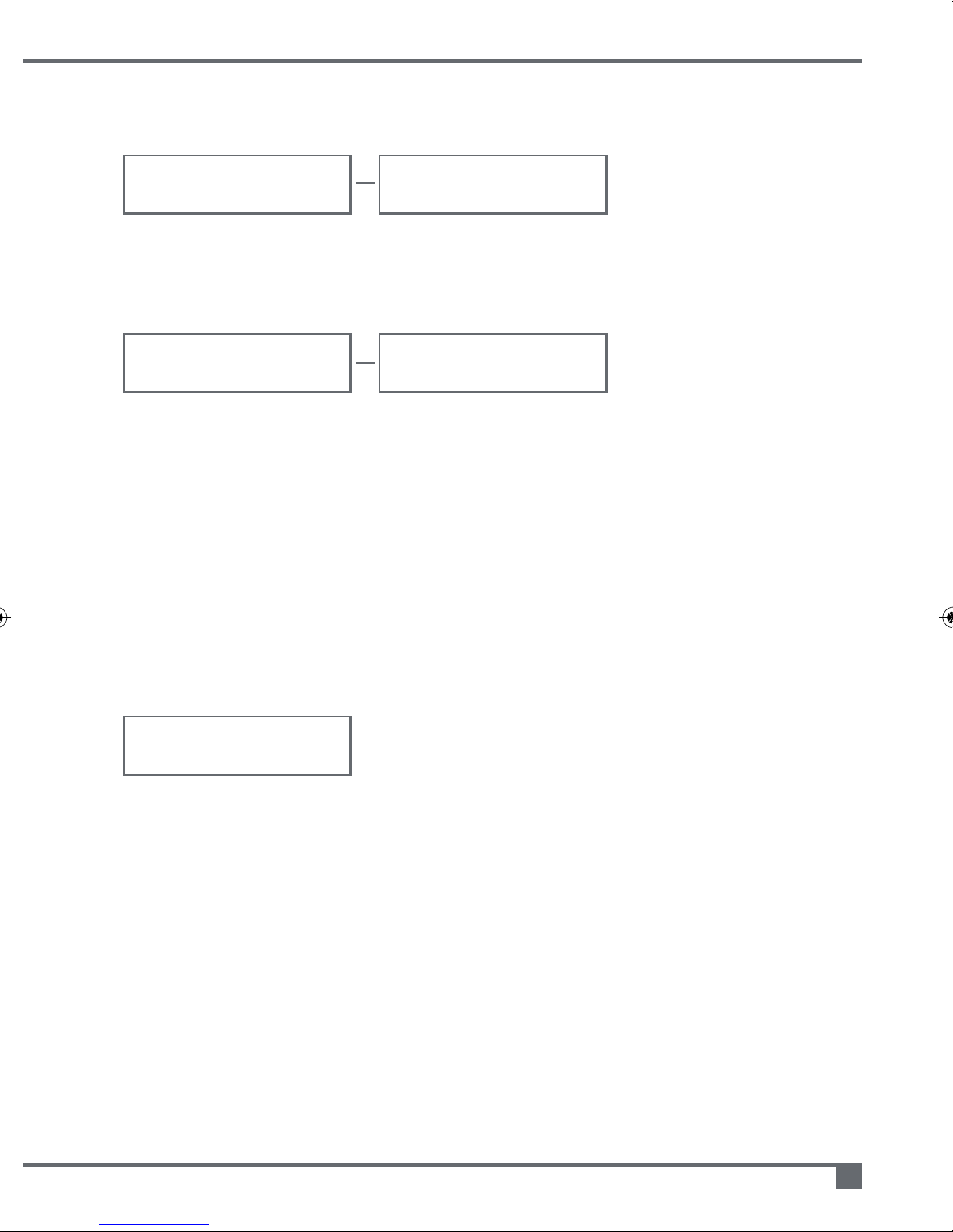
(2 messages flashing)
Signal from CTs insufficient for automatic phase sensing, proceed to manual
setup routine
6)
(2 messages flashing)
Non specific connection error
9
--
ID ERR 3
--
MTH-DAY HRS-MINS
2011 07.14 10.40
--
NOT FOUND
--
MTH-DAY HRS-MINS
2011 07.14 10.40
LO indicates which channel(s) has insufficient signal.
Increase phase current if possible, switch off, switch on (after 5 seconds) and try again.
Manual set up routine
Switch off e-Tracker, plug in EV-Trac probe and switch on after 5 seconds.
The SELF TEST routine starts.
PROBE SCAN
MTH-
NO SIGNAL
2011
07.14 10.40
Followed by:
Place the Probe along the phase cables’ insulation one at a time. Display indicates L1
or L2 or L3, clip-on the appropriate CT as below.
• Red CT on phase indicated as L1 (ignore phase cable colour)
• Yellow CT on phase indicated as L2
• Blue CT on phase indicated as L3.
If 'SIG ERR' displayed move Probe to different location on cable, away from other
phase cables.
Press enter
LO INPUT
MTH-
LO LO LO
2011
07.14 10.40
USE PROBE
MTH
LO LO LO
2012011
07.14 10.40
Page 10

e-Tracker portable energy monitor operating and maintenance manual
10
e-Tracker operational specification
Electrical
Current Input Clip-On or Flexeclamp CTs, 400mV. FS output
Current Range 50Amps full scale - 2500Amps full scale
Voltage Direct 3Ø 450V L-L 50Hz via voltage Clips
Voltage Direct 1Ø 240V 50Hz via 1Ø socket outlet
Voltage Nominal Adjustable 1Ø 220V +/- 10%, 3Ø 400V +/-10%
Pulse Input Volt free contact interface option
Battery Rechargeable cyclon 4V/2.5AH battery
Charge sources Integral charger via voltage connections
Battery life Approx 2 weeks of recorded current and calculated kVA only
Insulation inc CTs 2.5kV for 1min
Connection Leads CT to Plug 1.5m
Accuracy True RMS measurement of voltage & current
Clip-On CTs +/-1% percentage of reading @25°C for PF -0.7 -1
& 10% -100%IP
Flexeclamp CTs +/-2% of reading within conditions as above
Construction
Material ABS case with insulated magnetic mounting panel
Climatic Oper.Temp -10°C-+50°C, 95% RH (NC), IP30 protection
e-Tracker dimensions 177mm(w) x 295mm(h) x 50mm(d) Weight 4kg (full kit)
Standards
Calibration & Safety IEC 1036 and IEC 61010-1
EMC EN55022:1994, EN50082 Pt.1 1992
Memory Span
e-Tracker has capacity to store 16,000 lines of all parameters, either on one file or as
an aggregate total on up to five separate recording files. Recording will stop when
the memory is full.
Integration Period Mins. 60 30 20 15 10 5210.1(6s) H1(1sec)
Memory Duration Days 666 333 222 166 111 55 22 11 25 hrs 9 hrs*
*V1, V2, V3, I1, I2& I3only
Page 11
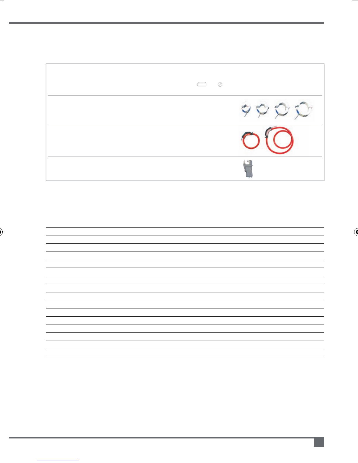
e-Tracker CT selection
CT Style CT Part NOMINAL Size Nominal Ip Accuracy Clip-on Outlines
Hinged Clip On TC16 16mm 54mm 4-200 1.0% 16x16 16
Flexeclamp Clip TF30 300mm length 10-1000 2.0% 20x85 75
Round TF40 400mm length 10-1500 2.0% 60x130 120
Precision Clip On THSSB 15mm 45mm 1-100 1.0% 15
Number ID OD Amps range PF-0.6 Capacity
TC32 32mm 72mm 5-500 1.0% 32x18 32
TC48 48mm 84mm 6-1000 1.0% 42x25 48
TC60 60mm 90mm 8-1500 1.0% 58x25 60
TF50 500mm length 20-2500 2.0% 70x150 155
TF60 600mm le
TF70 700mm length 20-2500 3.0% 70x265 215
ngth 20-2500 2.0% 70x200 190
to unity mm Nom
temp 25’c
50/60Hz
Deltrax5 software guidelines
Contents
1. The File List 12
2. The File Menu 12
2.1 Import from USB memory stick (e-Tracker Mk 2B) 12
2.2 Graph 13
2.3 Report 14
2.4 Delete 14
2.5 Show files 14
2.6 Manage data 14
2.7 Manage reports 14
3. The Preference Menu 15
3.1 Graph preferences 15
3.2 Change excel location 15
4. The Tariff Menu 16
4.1 Create tariff 16
4.2 Edit tariff 17
5. The Window Menu 17
6. Windows operating systems 17
e-Tracker portable energy monitor operating and maintenance manual
11
Page 12
Deltrax5 software guidelines
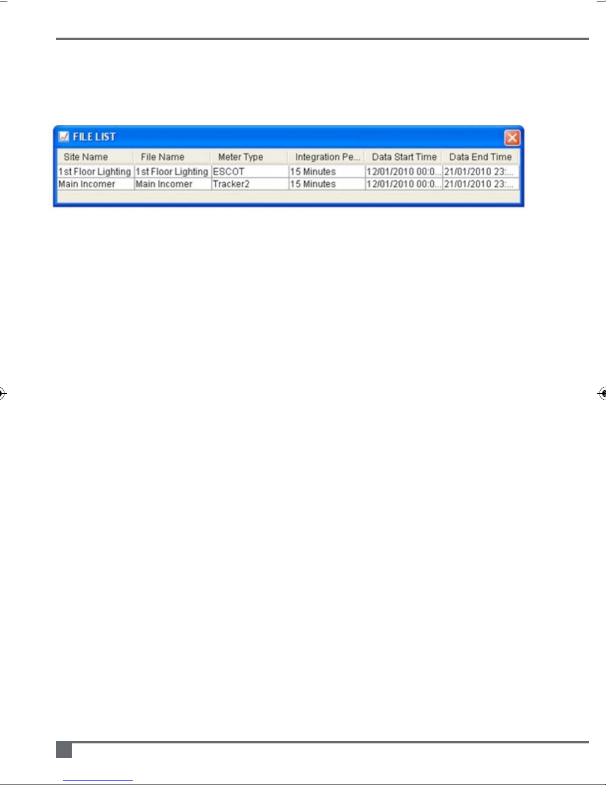
1. The file list
At the bottom of the Deltrax5 screen you will see a table called the ‘File List’. This table
contains all the data that you have downloaded or imported.
If you do not have data on your system then the table will just contain the words ‘No
Data’ in the first row of the table.
To perform any of the key Deltrax5 functions (graph, report, delete) you must have
selected a file in this table first.
Additionally, if you highlight a file and then click the right mouse button, you will get a
pop-up menu that will you permit you to select the graph, report and delete functions for
that data file.
You can remove the File List at any time by clicking on the red cross in the top right hand
corner - to bring it back just select the File - Show Files option from the menu bar.
2. The file menu
2.1 Import from USB memory stick (e-Tracker Mk 2B)
If you use the File-Import-Import from USB option from the menu then you will be able to
import e-Tracker MK 2B data.
Ensure that the USB memory stick with the data on is connected to your computer.
You will be directed to a standard file selection box where you need to locate the data
that is on your USB memory stick.
All e-Tracker MK 2B data is contained in files with a .dat extension.
e-Tracker portable energy monitor operating and maintenance manual
12
Page 13
13
2.2 Graph
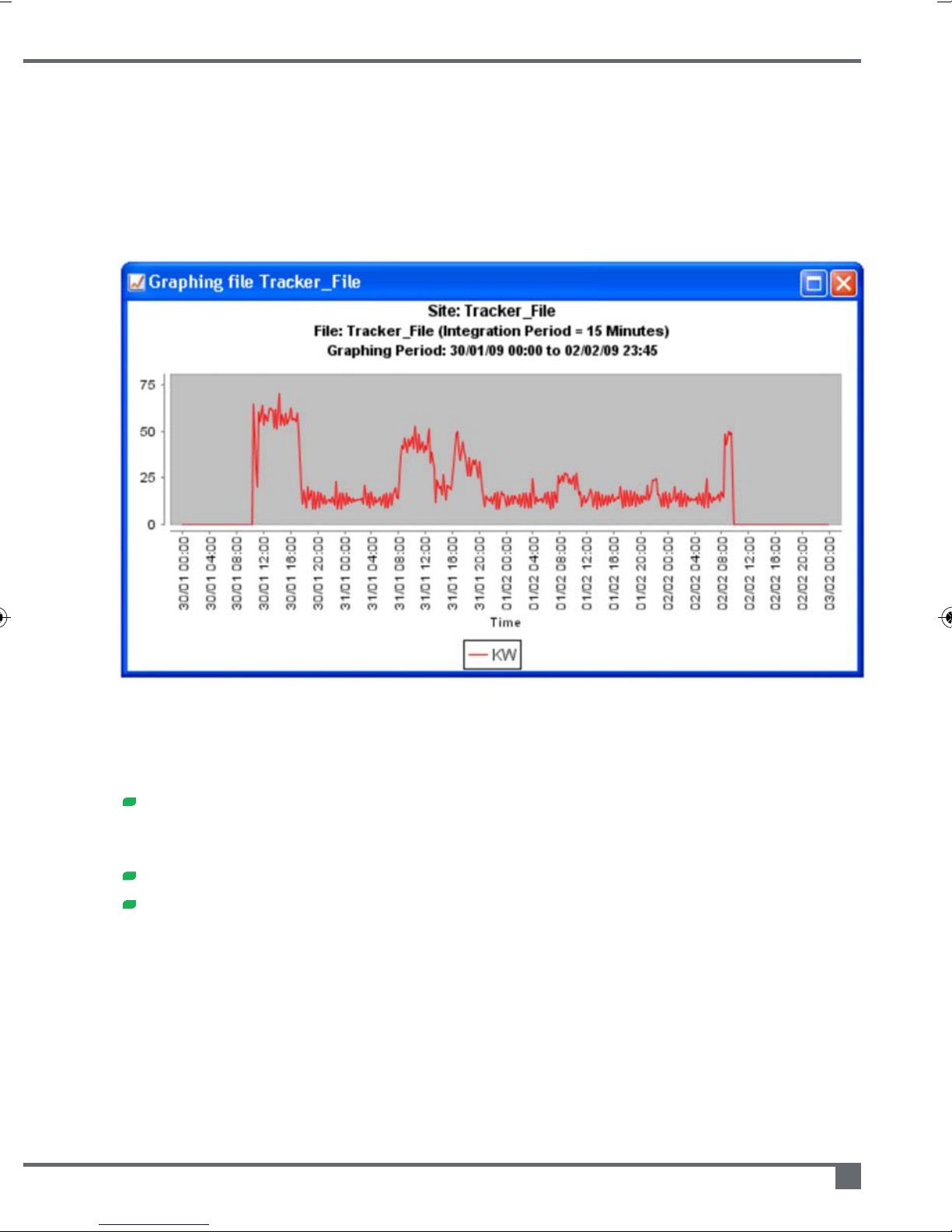
To show Deltrax5 data on a Graph you first need to select (highlight) a file in the File List box.
If you then use the File – Graph option from the menu, or click on the graphing icon (shown
above) then you will be shown the Date/Data selection options for the data that you want
to graph.
Once you have chosen the date/time and type of data that you want to see your graph
will be displayed on the screen.
Once the graph is displayed you have a number of options, you can:
Zoom in and out, draw a rectangle around the data you want to zoom in. Click
the mouse down at the top left of the rectangle, and release it at the bottom
right. To zoom out, click at the bottom right and release at the top left.
Hover over the line with the mouse pointer to get specific readings
Right click anywhere on the graph for more options, including printing
UsethePreferences–GraphPreferencesmenuitemtocustomizeyourgraph(please
refertoThepreferencesmenuonpage15).
Page 14

2.3 Report
To use Deltrax5 reporting facilities you first need to select (highlight) a file in the File List
box.
If you use then use the File – Report option from the menu, or click on the Reporting icon
(shown above) you will be taken to the report selection dialogue box. Depending on the
data that you are looking at you can usually select a Monthly, Weekly, Daily, or Excel
report. The first three of these reports are created on a PDF, and contain both a graph
and some tabular data. The Excel report is all the data written straight to an Excel
spreadsheet
If you choose a Monthly, Weekly or Daily report and your data spans more than one of
those time periods then you will be given the choice of which Month, Week or Day that
you want to view.
2.4 Delete
To use Deltrax5 delete facility you first need to select (highlight) a file in the File List box.
If you use then use the File – Delete option from the menu, or click icon shown above
then the file that you have selected will be deleted.
2.5 Show files
If you hide or close the File List box then the File – Show Files option will return it back
to the screen.
2.6 Manage data
Using the File – Manage Files menu option you can perform the following:
Archive your data; use the 'Move & Zip' option to write your data into a
compressed .zip file that can be read by other Deltrax5 systems.
Note: The Deltrax5 zip file is not a Win Zip file.
Delete your data, this facility also enables you to delete more than one file
at once.
2.7 Manage reports
Once a Deltrax5 Report is created it is within the system and can be viewed again and
again using the File – Manage Reports menu option. When it is no longer needed it can
be deleted from the system, as it is not linked to the data file that it originally came from.
Additionally, reports can be moved. A Deltrax5 report consists of a set of PDF files, or an
Excel file. If you want to provide this information to someone then use this facility to
send the report to the file location of your choice.
e-Tracker portable energy monitor operating and maintenance manual
14
Page 15
15
3. The preferences menu
3.1 Graph preferences
Using the Preferences – Graph Preferences option will give you the following options:
Line Colour – either choose industry standard or random colours for your graph
data
Default Shapes – setting Default Shapes ON will place shapes on your graph
data lines to make it easier to distinguish them if you print in black and white
Grid Lines – setting this option ON will apply grid lines to your graph background
Cross Hair – setting this option to ON will permit you to see horizontal and
vertical lines, which appear when you click on any part of the graph, enabling
you to read the axis values easier
Line Thickness – this option allows you to control the thickness of the Graphing
lines
Tariff to Apply – this option allows you to set which tariff is applied to any
graphs/reports that contain kW data. You have to have created a tariff within the
system to be able to do this (please refer to The tariff menu on page 16)
3.2 Change excel location
Using Preferences option the Change Excel Location menu item allows you to pinpoint
where on your PC you have Excel installed.
The default location for the installation of Excel is C:\Program Files\Microsoft
Office\Office, but some users may have this software on another drive or another
location.
More recent versions of Office have seen the Excel software being installed in any of the
following locations:
C:\Program Files\Microsoft Office\Office10
C:\Program Files\Microsoft Office\Office11
C:\Program Files\Microsoft Office\Office12
C:\Program Files\Microsoft Office\Office13
etc.
Page 16
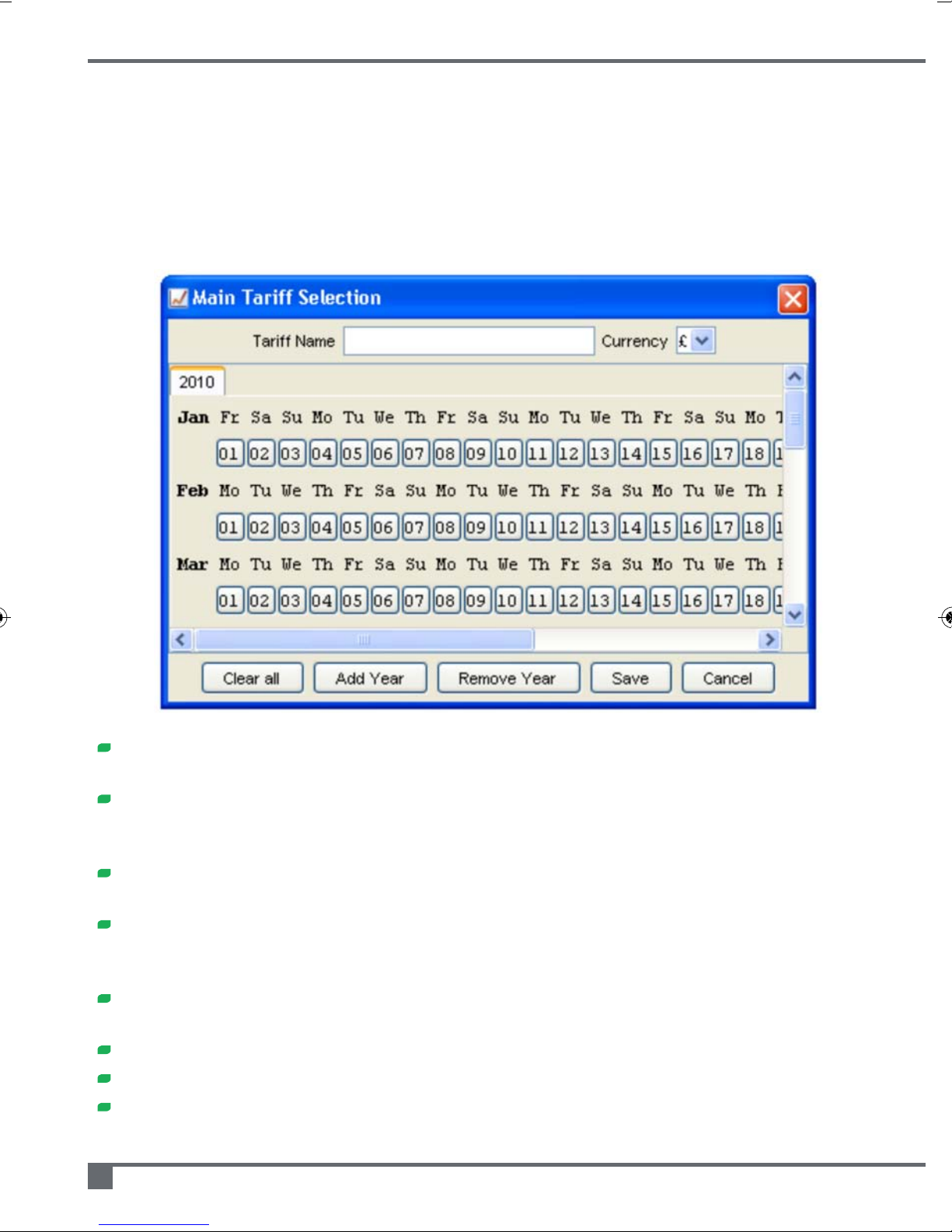
4. The tariff menu
4.1 Create tariff
If you use the Tariff – Create Tariff menu option you will be presented with a screen
similar to the one below.
Enter a Tariff Name and the select the Currency that you require from the drop
down selection box
Click on the first of the 'day buttons' (e.g. January 1st). You can then enter the 48
tariff values for that day (i.e. every half hour). There are 'copy forward' and 'clear'
functions to help limit entries.
When you have saved a 'day', you will notice that the 'day button' for that day
becomes bold to indicate that you have completed that day
If you right-click on a 'day button' you will see a number of options appear to
assist you with your input. They range from 'Copy Forward to Next Day' to 'Copy
forward to all days in Year'
Experimenting with the different 'Copy Forward' options means that you can
minimize the amount of keystrokes needed to enter a tariff for the year.
For Tariffs that span more than one year, use the 'Add Year' button
Always Save your Tariffs and the 'Days' within them
Remember – if you have more than one tariff saved, set the one that is used on
Graphs and reports using the Preferences – Graph Preferences menu option
e-Tracker portable energy monitor operating and maintenance manual
16
Page 17

17
4.2 Edit tariff
If you use the Tariff – Edit Tariff menu option you will be able to edit or delete the tariffs
that you have created during Create Tariff (previous page).
5. The window menu
Use the Window – Arrange and Window – Close menu items to organise the windows
that you may have open on your screen.
6. Windows operating systems
The Deltrax5 CD contains software that should automatically install the current
drivers/software to suit the PC it is being installed on.
Page 18

Trouble shooting
If you are experiencing difficulties with your e-Tracker, please consult the points below.
However if your problem is still not resolved please contact Marshall-Tufflex Energy
Management on +44 (0)1424 856610.
If the unit will not switch on and has no display try the following:
1) Your battery could be flat, please place on charge for at least half a day with on/off
switch in off position, use mains lead to charge (Note ensure 3Amp fuse in 13Amp
plug is okay).
2) If charging fails to cure the problem, either the battery is flat or your e-Tracker
program could be corrupted. Your unit would need to be returned to factory for
reprogramming or to fit a new battery.
3) If charging fails to cure the problem, the internal fuse may have blown. Your unit
would need to be returned to the factory for investigation.
Pleasenote:afaultybattery,corruptprogramorblowninternalfusecangivethesame
symptoms.
On screen error messages:
CT’s odd
At least one of the three CTs does not match, or at least one of the three CT cables is
damaged thus causing the “CTs odd” message. In turn test each of the CTs using CT1
input only, the rogue CT can be identified as it will produce a different Amp range to the
other CTs (when going through the e-Tracker's set-up procedure).
For further help and information please contact our team on +44 (0)1424 856610
or visit www.marshalltufflexenergy.com
e-Tracker portable energy monitor operating and maintenance manual
18
Page 19

Page 20

Marshall-Tufflex Energy Management Ltd
Churchfields Industrial Estate Hastings
East Sussex TN38 9PU
www.marshalltufflexenergy.com
In pursuance of our policy of continued improvement Marshall-Tufflex Energy Management
reserve the right to change the design or specification of its products without notification.
EY120/11104
 Loading...