

Marshalltown FS13 Owner's Manual
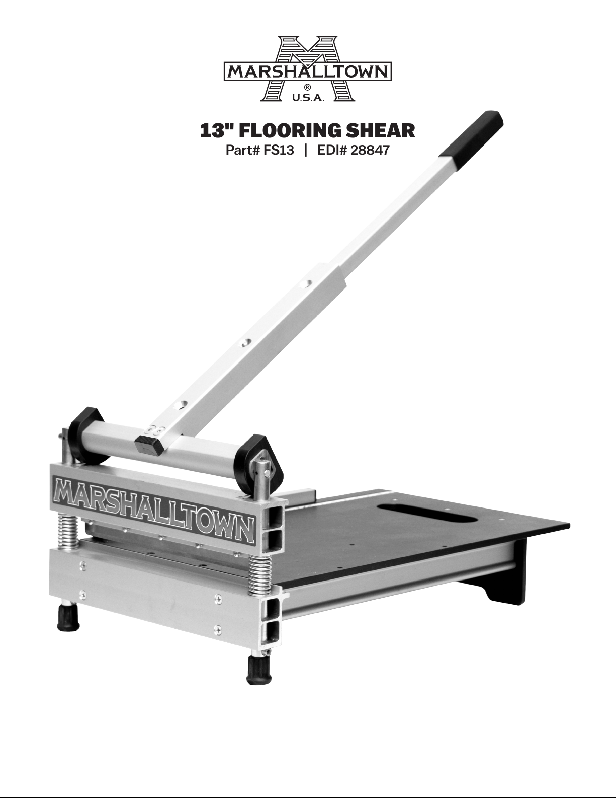
" FLOORING SHEAR
Part# FS13 | EDI# 28847
104 S. 8th Ave. | Marshalltown, IA
Phone 800-888-0127 / 641-753-0127 | Fax 800-477-6341 / 641-753-6341
www.MARSHALLTOWN.com
WS1980

INTRODUCTION
Congratulations on your purchase of a MARSHALLTOWN Flooring Shear. Proudly made in the USA,
MARSHALLTOWN flooring shears are heavy duty and manufactured with the highest grade materials.
MARSHALLTOWN shears are designed with the flooring professional in mind to ensure accuracy and reliability.
Other features of your MARSHALLTOWN flooring shear include:
• Easy, quiet one-cut action
• Ability to cut inside and produce no dust
• Cut material up to 13" (330mm) wide and 1" (25.4mm) thick
• Built in ruler for accurate cuts
• Moveable fence for 90° and 45° cuts
This owner’s manual provides the information needed to operate and maintain this MARSHALLTOWN flooring
shear. Carefully read and follow all safety and operating instructions in this manual. Ensure every operator of this
flooring shear reads this manual before operating the unit. The replacement of any part on this flooring shear by
other than the manufacturer’s authorized replacement part may adversely affect the performance, durability or
safety of the product.
Be sure safety precautions are observed. Read and follow all safety and operating instructions in this
operator’s manual. The manufacturer reserves the right to make changes on or add improvements to its
product at any time without prior notice or obligation. The manufacturer reserves the right to decide, upon its
sole discretion and at any time, to discontinue this product.
This manual covers the MARSHALLTOWN 13" Flooring Shear. For technical questions or repair parts, please call
MARSHALLTOWN customer service at 1-800-888-0127 or visit www.MARSHALLTOWN.com.
2 of 12
104 S. 8th Ave. Marshalltown, IA Phone 800-8 88-0127 / 6 41-753-012 7 • Fax 800-47 7-6341 / 6 41-753-6341 www.MARSHALLTOWN.com WS1980
DANGER!
WARNING!
WARNING!
WARNING!
TABLE OF CONTENTS
Safety Precautions ......................................................................................................................................................................3
Safety Decals ...............................................................................................................................................................................4
Warranty ........................................................................................................................................................................................4
Assembly ..................................................................................................................................................................................5-6
Product Operation ......................................................................................................................................................................7
Cutting Guide ...............................................................................................................................................................................8
Parts Breakdown ....................................................................................................................................................................8-9
Maintenance ..............................................................................................................................................................................10
Trouble Shooting........................................................................................................................................................................ 11
SAFETY PRECAUTIONS
• DANGER or
WARNING safety signs are located near specific hazards.
• General precautions are listed on CAUTION safety signs.
• This notation appears before warnings in the text. It means that the step that follows must be carried out to
avoid the possibility of personal injury or death. These warnings are intended to help the technician avoid any
potential hazards encountered in the normal service procedures. We strongly recommend that the reader
takes advantage of the information provided to prevent personal injury or injury to others.
THE FOLLOWING PRECAUTIONS ARE SUGGESTED TO HELP PREVENT ACCIDENTS. A CAREFUL OPERATOR
IS THE BEST OPERATOR. MOST ACCIDENTS CAN BE AVOIDED BY OBSERVING CERTAIN PRECAUTIONS.
READ AND TAKE THE FOLLOWING PRECAUTIONS BEFORE OPERATING THIS EQUIPMENT TO HELP
PREVENT ACCIDENTS. EQUIPMENT SHOULD BE OPERATED ONLY BY THOSE WHO ARE RESPONSIBLE AND
INSTRUCTED TO DO SO.
CALIFORNIA PROPOSITION 65 WARNING: This product can expose you to chemicals known to the
State of California to cause cancer, birth defects, or other reproductive harm.
• Read all operating and maintenance instructions before operating or servicing the flooring shear.
• A flooring shear is only as safe as its operator. Give complete and undivided attention to the operation of the
flooring shear.
• Know how to stop the flooring shear instantly.
NEVER operate the flooring shear if any shear components have been removed.
• Keep inexperienced and unauthorized people away from the flooring shear at all times.
• Keep the flooring shear in good operational condition. Loose or damaged parts are dangerous.
• Avoid loose clothing that could get caught in moving parts.
Keep hands and feet away from moving parts.
• Keep all warning, caution and safety instruction labels in good condition. Replace missing, damaged or illegible labels.
• Clear the work area around the shear to prevent tripping or falling onto the shear.
• Operate on level ground to prevent the flooring shear from flipping over.
•
DO NOT OPERATE this flooring shear under the influence of alcohol or while taking medication that impairs your reactions.
• Use only factory authorized parts for replacement.
• Wear safety glasses when operating the flooring shear.
• Always use caution when replacing the shear blade.
• Only operate the shear with the approved materials. If extreme force is required to cut a material, it may result in personal
injury and/or damage to the flooring shear.
• Wear proper protective clothing while operating flooring shear, including eye, ear, and clothing.
• Handle all solvents and cleaning agents with care and follow manufacturer’s instructions on safety and disposal.
104 S. 8th Ave. Marshalltown, IA Phone 800-8 88-0127 / 6 41-753-012 7 • Fax 800-47 7-6341 / 6 41-753-6341 www.MARSHALLTOWN.comWS1980
3 of 12

SAFETY DECALS
If your safety decals are damaged, they can be replaced by contacting Customer Service.
WS2020
WS2021
WARRANTY
This product is warranted to the original purchaser only, to be free of defects in material and workmanship
under normal use, for one year from purchase date. MARSHALLTOWN shall without charge for parts and labor,
repair or replace such parts which are found to be defective. All transportation charges for replacement parts
must be borne by the purchaser.
For warranty service, the product must be delivered, with proof of purchase date, to MARSHALLTOWN.
Contact MARSHALLTOWN Customer Service to determine the best method of delivering the product that is
under warranty. The delivery of the product must be made no later than 30 days after the expiration of the
warranty period.
All implied warranties, including those of merchantability and fitness for a particular purpose, are limited to one
year from date of purchase by the original retail customer and to the extent permitted by law any and all implied
warranties are excluded and disclaimed after the expiration of such period.
Some states do not allow limitations on how long an implied warranty lasts, or the exclusion or limitations of
incidental or consequential damages, so the above limitations or exclusions may not apply to you. This warranty
gives you specific legal rights, and you may also have other rights, which vary from state to state.
Exclusion from this warranty:
1. All consequential damages, including pickup and delivery of the unit, communication, mileage charges and/
or rental of a replacement unit during repairs are not covered under this warranty, or are any loss of income
and/or other loss resulting from the failure of the product to function due to a warranty defect.
2. This warranty will not apply when the product becomes inoperative due to misuse, normal wear, neglect,
improper maintenance, accident or freight damage; has not been operated and maintained in accordance
with the instructions furnished in the Operator’s Manual; or has been altered or modified without approval
from the factory Service Department.
3. No parts or products are to be returned to the factory without prior written approval from the factory.
4 of 12
104 S. 8th Ave. Marshalltown, IA Phone 800-8 88-0127 / 6 41-753-012 7 • Fax 800-47 7-6341 / 6 41-753-6341 www.MARSHALLTOWN.com WS1980
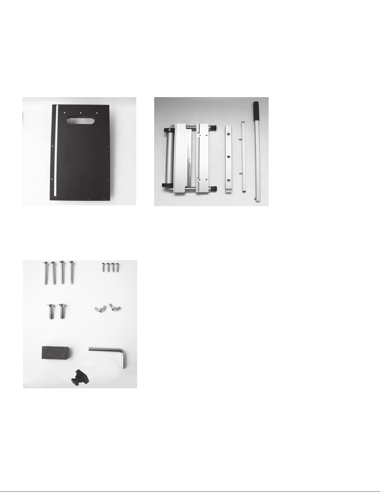
1. Lay out all of the parts.
Tools for Assembly:
• #2 Phillips Screwdriver
• #3 Phillips Screwdriver
• " Hex Wrench (included)
A B C D E
ASSEMB LY
A. Table Assembly
B. Shear Assembly
C. Handle Base
D. Bed Fence
E. Handle Extension
F
H
J
L
2. Lay out all hardware.
G
I
K
F. #3 Phillips Flat Head Screw, "–20 X 2 " (4x)
G. #2 Phillips Flat Head Screw, 10-24 X " (4x)
H. " Hex Drive Flat Head Screw, "–18 X 1 " (2x)
I. Wing Nut, "–20 (2x)
J. Honing Stone (1x)
K. Cam Locking Pin (1x)
L. End Cap (1x)
104 S. 8th Ave. Marshalltown, IA Phone 800-8 88-0127 / 6 41-753-012 7 • Fax 800-47 7-6341 / 6 41-753-6341 www.MARSHALLTOWN.comWS1980
5 of 12
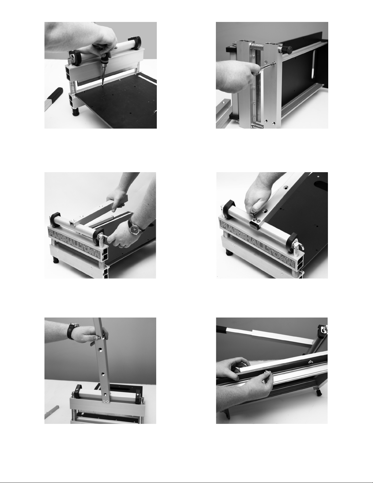
3. Attach Table Assembly (A) and Shear Assembly
(B) using hardware set G.
4. Attach the bed brace extrusion from the Table
Assembly (A) to the Shear Assembly (B) using
hardware set F.
5. Attach Handle Base (C) to Shear Assembly (B) using
one screw from hardware set H. Press the Handle
Base (C) down and insert Cam Locking Pin (K).
7. Press in the spring button and insert Handle
Extension (E) into Handle Base (C).
6 of 12
104 S. 8th Ave. Marshalltown, IA Phone 800-8 88-0127 / 6 41-753-012 7 • Fax 800-47 7-6341 / 6 41-753-6341 www.MARSHALLTOWN.com WS1980
6. Remove Handle Base (C), insert End Cap (L) bevel
side down into Handle Base (C) and reattach to
Shear Assembly (B) using hardware set H.
8. Place the Bed Fence (D) in two holes on the right
side of Table Assembly (A) and attach using
hardware set I.
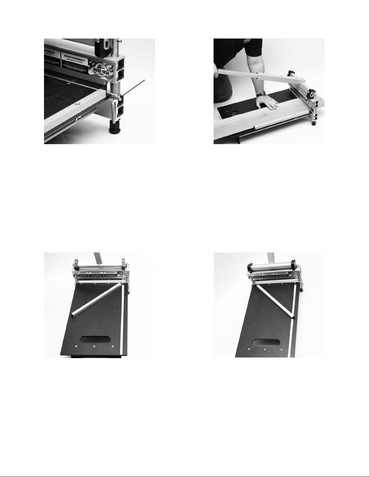
PRODUCT OPERATION
1. Press down handle and carefully remove the
Cam Locking Pin. Insert Cam Locking Pin into its
storage hole to prevent losing the pin. Carefully
raise and release the handle.
2. Place material to be cut on the table and slide past
the blade to the desired length. Press flooring
against the Bed Fence and hold firmly in place to
ensure a clean and accurate cut. Press handle
down until the blade touches the material and then
firmly press down on the handle until the material
is cut.
DEGREE CUTS
1. Loosen wing nuts and remove the Bed Fence. Insert the fence into either of the angled holes for the desired
cut and tighten wing nuts.
DOUBLE CUTTING
Some materials may require the double cutting method to obtain a clean cut. For these materials, make your
first cut " longer than your mark. Then, make a second cut on your mark. This method will help produce
cleaner cuts on some materials.
104 S. 8th Ave. Marshalltown, IA Phone 800-8 88-0127 / 6 41-753-012 7 • Fax 800-47 7-6341 / 6 41-753-6341 www.MARSHALLTOWN.comWS1980
7 of 12
CUTTING GUIDE
The MARSHALLTOWN Flooring Shear is designed to cut a variety of materials. Some of the most common
materials are laminate flooring, engineered hardwood, luxury vinyl tile, luxury vinyl plank, vinyl composite tile,
fiber cement board siding, and more.
Note: DO NOT attempt to cut any solid wood, high pressure laminate, or engineered hardwood with a
Janka Hardness Rating higher than 1300.
Note: Even the approved materials may vary greatly in density and hardness. If extreme force is required to cut
a material stop immediately, as it could lead to damage to your shear or injury. Attempting to cut unapproved
materials will void the warranty.
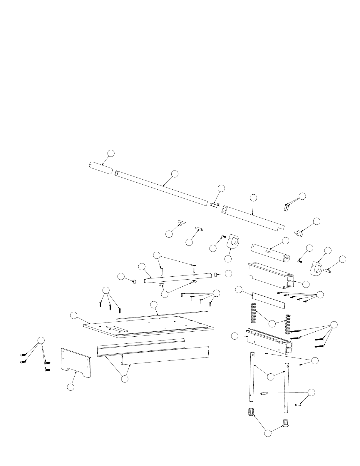
PARTS BREAKDOWN
30
29
28
1
4
32
12
20
14
2
31
7
24
27
23
22
25
3
26
15
7
5
8
16
19
14
18
10
17
15
20
13
6
11
21
8 of 12
9
104 S. 8th Ave. Marshalltown, IA Phone 800-8 88-0127 / 6 41-753-012 7 • Fax 800-47 7-6341 / 6 41-753-6341 www.MARSHALLTOWN.com WS1980

PARTS BREAKDOWN
REF # DESCRIPTION PART# Quantity
1 HANDLE BASE R4529 1
2 #3 PHILLIPS FLAT HEAD SCREW, 1/4"-20 X 1 1/2" WR1386 2
3 WING NUT, 1/4"-20 WR1382 2
4 3/16" HEX DRIVE FLAT HEAD SCREW, 5/16”–18 X 1 1/4" WR1383 2
5 #2 PHILLIPS FLAT HEAD SCREW, 10-24 X 3/4" WR1384 4
6 #3 PHILLIPS FLAT HEAD SCREW, 1/4"-20 X 2 1/2" WR1385 4
7 PLASTIC CAP WL710 2
8 BLADE WX2417 1
9 SLIP-ON FOOT, 3/4" WK219 2
10 COMPRESSION SPRING WX2424 2
11 SET SCREW, 10-24 X 3/16" WR1377 2
12 CAM LOCKING PIN WU904 1
13 #2 PHILLIPS PAN HEAD SCREW, 1/4"-20 X 1/2" WR1158 5
14 #3 PHILLIPS PAN HEAD SCREW, 1/4"-20 X 3/4" WR1378 2
15 EXCENTRIC CAM WX2425 2
16 ANVIL BEAM R4525 1
17 GUIDE ROD WU903 2
18 BLADE BEAM R4526 1
19 CAM BAR R4527 1
20 CAM PIN WU905 2
21 SPRING PIN, 3/8" DIA X 1 1/4" LONG WR1379 2
22 BED BRACE EXTRUSION WC921 2
23 #3 PHILLIPS PAN HEAD SCREW, 1/4"-20 X 1" WR1380 4
24 #2 PHILLIPS FLAT HEAD SCREW, #10 X 1" LONG WR1381 3
25 LEG R4531 1
26 ADHESIVE RULE WX2426 1
27 BED WL708 1
28 SPRING BUTTON WT173 1
29 EXTENSION HANDLE R4528 1
30 SOFT GRIP WT507 1
31 BED FENCE R3944 1
32 END CAP WL741 1
104 S. 8th Ave. Marshalltown, IA Phone 800-8 88-0127 / 6 41-753-012 7 • Fax 800-47 7-6341 / 6 41-753-6341 www.MARSHALLTOWN.comWS1980
9 of 12
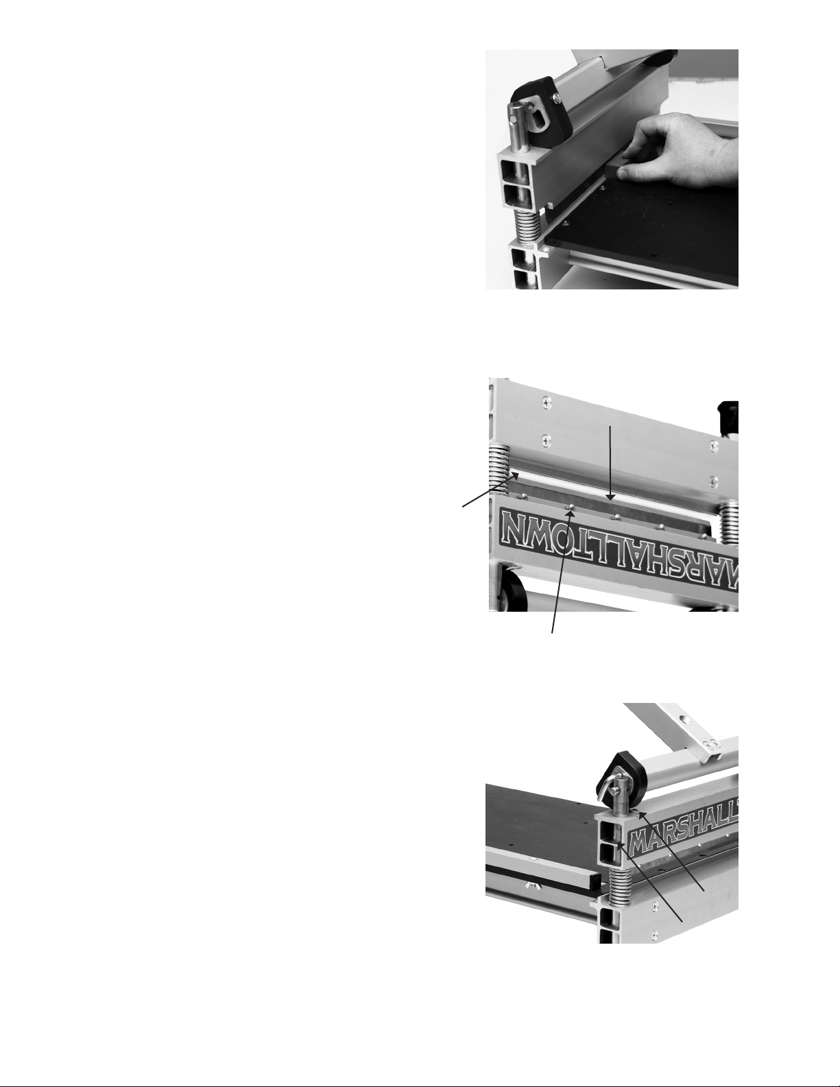
MAINTENANCE
Honing the Blade
Push the handle down until the blade 1/8” (3mm)
above the tabletop. Place the provided Honing Stone
(J) against the flat side of the blade. Slide the honing
stone from one end of the blade to the other 3-4
times. This will remove any burrs from your blade and
should be done every 100 cuts. Use caution when
honing the blade. The blade is sharp and can easily
cause injury. Cut resistant gloves are recommended
when honing the blade.
Replacing the Blade
Use cut-resistant gloves when replacing the blade.
Cover the cutting edge with a blade guard or other
suitable covering. Place the shear upside down on
a workbench with the jaws in the open position,
creating a gap to allow blade removal. To remove the
blade use a #2 Phillips screwdriver and loosen the
5 retaining screws one full turn counterclockwise.
Do not remove the screws. When the last screw is
loosened, the blade will slip out of the retaining slot.
Cover the cutting edge of the new blade with a blade
guard or other suitable covering. Slide the new blade
into the slot with the beveled edge facing the screws.
Center the blade in the slot and make sure the blade
is fully inserted. Hand-tighten the center screw.
Hand-tighten the remaining screws to complete the
installation.
Beveled edge
on blade facing
retaining screws
Gap
Retaining screws
Lubrication
After every 100 cuts, it is recommended that the
shear be lubricated. Use a light oil and grease (wheel
bearing grease) and apply according to the image
below. Lubricating the shear will extend the life of the
shear and result in easier cutting.
10 of 12
104 S. 8th Ave. Marshalltown, IA Phone 800-8 88-0127 / 6 41-753-012 7 • Fax 800-47 7-6341 / 6 41-753-6341 www.MARSHALLTOWN.com WS1980
Grease
Oil

TROUBLESHOOTING
ISSUE RESOLUTION
Shear won’t cut desired material
Shear is leaving a jagged edge on flooring
Shear requires more force to cut than normal
Review cutting guide in manual to confirm it is a
confirmed material. Contact MARSHALLTOWN
customer service. Do not attempt to use
extreme force to cut the material.
Use honing stone to carefully touch up the blade
as described in the manual. Use double cutting
method as described in the manual if necessary.
Use honing stone to carefully touch up the
blade as described in the manual. Follow the
maintenance section of the manual to oil and
grease the shear.
104 S. 8th Ave. Marshalltown, IA Phone 800-8 88-0127 / 6 41-753-012 7 • Fax 800-47 7-6341 / 6 41-753-6341 www.MARSHALLTOWN.comWS1980
11 of 12
 Loading...