

Page 1
WS500
2-2012/Rev.A
OPERATIONS MANUAL
& PARTS LIST
MODEL: 600cm
6 CU. FT.
104 S. 8th Ave.
Marshalltown, IA
Phone 800-888-0127 / 641-753-0127
Fax 800-477-6341 / 641-753-6341
www.marshalltown.com
1 of 16
Page 2

2 of 16
Page 3

INTRODUCTION
This owner’s manual provides the information needed to operate and maintain this Gilson by Marshalltown Mixer. Carefully
read and follow all safety and operating instructions in this manual. Also, be sure every operator of this mixer reads this
manual before operating the mixer. The replacement of any part on this mixer by other than the manufacturer’s authorized
replacement part may adversely affect the performance, durability or safety of the product.
Be sure safety precautions are observed. Read and follow all safety and operating instructions in this operator’s manual.
The manufacturer reserves the right to make changes on, or add improvements to its product at any time without prior
notice or obligation. The manufacturer reserves the right to decide, upon its sole discretion and at any time, to discontinue a
product.
Information regarding operation and maintenance of the engine can be found in a separate engine manual supplied with
this mixer if the mixer is supplied with an engine. The engine manual provides all the information required regarding engine
adjustments, operation and maintenance. Should any questions arise concerning engine operation or service, contact the
nearest engine repair facility or the engine manufacturer.
TABLE OF CONTENTS
Safety Precautions ..........................................................................………………………………….4
Towing & Safety Chains ..............................................................……………………………………. 4
Warranty Information .......................................................................................................................5
Lubrication And Storage ...............................................................................................................6-7
Mixing Instructions ........................................................................................................................... 7
Care of Mixer .................................................................................................................................7
Parts List ...................................................................................................................................8-15
IMPORTANT: if safety or standard decals are missing, illegible, or damaged, they should be replaced.
Please contact Marshalltown Customer Service at 800-888-0127 • 641-753-0127 for replacement decals.
3 of 16
Page 4
SAFETY PRECAUTIONS
This is the industry’s safety alert symbol. This symbol calls attention to items or operations that could be
dangerous. This symbol can be found throughout this manual and on safety decals on the mixer. Read
these messages carefully.
THE FOLLOWING PRECAUTIONS ARE SUGGESTED TO HELP PREVENT ACCIDENTS. A CAREFUL
OPERATOR IS THE BEST OPERATOR. MOST ACCIDENTS CAN BE AVOIDED BY OBSERVING
CERTAIN PRECAUTIONS. READ AND TAKE THE FOLLOWING PRECAUTIONS BEFORE OPERATING THIS
EQUIPMENT TO HELP PREVENT ACCIDENTS. EQUIPMENT SHOULD BE OPERATED ONLY BY THOSE WHO ARE
RESPONSIBLE AND INSTRUCTED TO DO SO.
1. Read all operating and maintenance instructions before operating or servicing mixer. Test run empty prior to actual use.
2. A mixer is only as safe as its operator. Give complete and undivided attention to the operation of the mixer.
3. Know how to stop the mixer and the engine instantly.
4. Always have all guards and safety devices attached and in place before operating mixer. Close engine housing
during operation.
5. Keep inexperienced and unauthorized people away from the mixer at all times.
6. Never leave the mixer unattended while it is running.
7. Shut off engine or disconnect the electric motor before making any adjustments or putting hands or tools in the drum.
8. Do not overfill the drum. Do not exceed the mixer’s rated capacity.
9. Do not smoke while refueling the engine. Shut off the engine and allow it to cool before refueling. Do not spill fuel.
10. Block mixer wheels when mixing.
11. Use safety chains while towing mixer.
12. Keep the mixer in good operating condition. Loose or damaged parts are dangerous.
13. Avoid loose clothing that could get caught in moving parts or on control levers.
Keep hands and feet away from moving parts
14. Do not add material to the drum while stopped. Start the drum before adding material.
15. Keep all warning, caution and safety instruction labels in good condition. Replace missing, damaged or illegible labels.
Never reach into the drum or place tools into the drum while the mixer is running
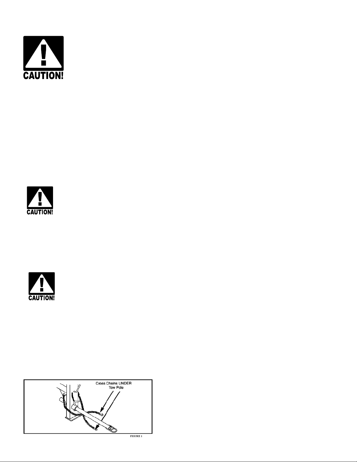
TOWING & SAFETY CHAINS
For transporting the mixer, slide the tow pole out as far as possible and insert the locking pin. When operating the mixer,
slide the tow pole in and lock it in place. Make sure drum is locked in position and engine housing is closed and secured.
Cross the safety chains under the tow pole and fasten them to the tow vehicle. (fig.1)
4 of 16
NOTE! Safety chain length may need to be altered for proper
connection to tow vehicle. Reposition the hooks, DO NOT cut chain.
Allow enough slack to permit proper vehicle turning while keeping
chains snug enough to prevent tow pole from contacting the ground in
case the hitch uncouples.
Page 5

WARRANTY
This mixer is warranted to the original purchaser only, to be free of defects in material and workmanship under normal use,
for one year from purchase date. Marshalltown Company shall without charge, repair or replace parts which are found to be
defective. All transportation charges for replacement parts must be bourne by the purchaser.
For warranty service, the product must be delivered, with proof of purchase date, to the dealer of original purchase, or any
factory authorized service dealer. The delivery of the unit must be made not later than 30 days after the expiration of the
warranty period.
EXCLUSIONS FROM WARRANTY:
1.The following items are not covered under the Gilson by Marshalltown Mixer One Year Limited Warranty and are
warranted by the respective manufacturer:
A. Engines, including starters, generators, alternators and gear reducers.
B. Hydraulic components, including pumps, motors and valves
2. All consequential damages, including pickup and delivery of the unit, communication, mileage charges and/or
rental of a replacement unit during repairs, are not covered under this warranty, nor is any loss of income and/or
other loss resulting from the failure of the product to function due to a warranty defect.
3.This warranty will not apply when the product becomes inoperative due to misuse, normal wear, neglect, improper
maintenance, accident, or freight damage; has not been operated and maintained in accordance with the instructions
furnished in the Operator’s Manual; or has been altered or modified without approval from the factory Service Dept.
4. No parts or products are to be returned to the factory without prior written approval from the factory.
All implied warranties, including those of merchantability and fitness for a particular purpose, are limited to one
year from date of purchase by the original retail customer and to the extent permitted by law any and all implied
warranties are excluded and disclaimed after the expiration of such period.
Some states do not allow limitations on how long an implied warranty lasts, or the exclusion of limitations of
incidental or consequential damages, so the above limitations and exclusions may not apply to you.
This warranty gives you specific legal rights, and you may also have other rights, which vary from state to state.
NOTICE: Record the model and serial numbers of the mixer (located on the nameplate) in the spaces provided.
Engine model, type and code numbers are located on the blower housing, cylinder head or backplate.
Product Model Number: ______________________________________________
Product Serial Number: _______________________________________________
Engine/Motor Model Number: _________________________________________
Engine/Motor Code Number: __________________________________________
Purchase Date: ______________________________________________________
Dealer Purchased From: ______________________________________________
Dealer Address: ______________________________________________________
____________________________________________________________________
____________________________________________________________________
Dealer Phone Number: ________________________________________________
5 of 16
Page 6

PRIOR TO START UP
1. Examine the mixer carefully to make sure there was no damage during shipment or since the last use. Report any
damage immediately to the transportation company. Repair any damage before using the mixer.
2. Check for free rotation of the mixer drum yoke by rotating the drum through one complete dump-charge-dump cycle.
Make sure no foreign objects or tools are in the drum before starting the motor.
3. Check the engine oil. Fill as required. Refer to the engine manual for oil specifications.
4. Fill the fuel tank with fresh, clean fuel. Refer to the engine manual for fuel specifications.
5. Grease all fittings as called out in the lubrication specifications.
6. Start the motor and check for smooth operation of the drum, ring gear, and pinion.
Note: After initial 10 hours of operations, check chain/belts for proper tension and sprockets/pulleys for alignment. Check
these items monthly to prevent premature wear/failure.
LUBRICATION
Use lithium based grade 2 multi-purpose grease.
Drum Shaft Tube:
Drum shaft lubrication can be performed by removing the 1/8” pipe plug and installing the appropriate
grease fitting. Greasing should be done yearly.
Yoke Bearing Hangers:
Yoke bearing hangers are located on the yoke ends and are equipped with grease fittings. These bearings should be
greased weekly.
Wheel Bearings:
Grease wheel bearings once per year. Thoroughly remove old grease from bearings and spindle before repacking.
Pack bearings 1/2 to 2/3 full to prevent overheating.
Drum Tilt Brake Bearing:
The brake bearing casting is located near the front of the mixer and should be greased weekly.
Handwheel Bearing:
The handwheel hub bearing is located on the front of the mixer, behind the handwheel. This bearing should be
greased weekly.
WARNING: DO NOT GREASE BRAKE BAND OR OUTER BRAKING SURFACE OF TILT GEAR.
Jack Shaft Bearings:
Pillow block style bearings are used on the drive train counter shaft. These bearings should be greased weekly.
Drive Chain:
The drive chain should be lubricated monthly with SAE #20 or SAE #30 oil. Apply the oil between the side plates.
Engine/Motor:
Refer to the manufacturer’s engine or motor operating instructions for all maintenance and lubrication requirements and
instructions.
LUBRICATION FREQUENCY CHART:
ITEM FREQUENCY CODE PLACES
Drum Shaft Tube yearly grease 1
Yoke Bearing Casting weekly grease 2
Wheel Bearings yearly grease 2
Drum Tilt Brake Bearing Casting weekly grease 1
Handwheel Hub weekly grease 1
Drive Shaft weekly grease 1
Jackshaft (Electric motor only) weekly grease 2
6 of 16
Drive Chain monthly oil 1
Page 7

STORAGE
For short term storage, clean the mixer and store in a dry place. If the mixer is not to be used for an extended period of
time, service mixer completely and store it in a dry place.
1. Refer to motor/engine instructions for storage instructions.
2. Cover exposed metal surfaces with a thin coat of SAE 30 engine oil.
3. Lubricate per instructions under LUBRICATION & STORAGE section.
GETTING READY FOR MIXING
Lay out forms for your concrete floor, patio, driveway, sidewalk, etc. The quality of concrete is directly related to the quality of
the cement paste. The quality of the paste, in turn, is directly related to the amount of water mixed with the cement. For a
given amount of cement, as the amount of mixing water is reduced, the strength of the paste increases, making the concrete
stronger and more durable. Calculate the proportions of your mix components (cement, sand and coarse aggregate)
according to the job specifications.
LOADING THE MIXER
Start the mixer. Refer to motor/engine instructions. After drum has started rotating, pour about half of the water in the drum.
NOTE: The drum my leak slightly when first used. This will stop after a few batches. Add aggregate (gravel) first then
cement and last sand.
MIXING INSTRUCTIONS
1. Start the drum rotating.
2. Add water.
3. Add cement and one shovelful of coarse aggregate. The coarse aggregate will break up any lumps in the cement.
4. Add remaining aggregate: crushed stone, pit-run gravel or sand.
5. Mix batch for approximately one minute. Drum speed should be about 25 r.p.m.
UNLOADING THE MIXER Refer to Fig. 1
Allow the entire mixture to mix for one full minute. Do not stop mixer from rotating.
Hold the tilt handle and unlock the stop lever. Dump concrete to either side by tilting
the tilt handle in the direction required. Before reloading the mixer, slowly pour a pail
of water over the lip of the drum, permitting water to clean the inside of drum. Mix
batch for approximately one minute. Drum speed should be about 25 r.p.m. When
cleaned, dump water. Now you are ready for your next batch.
Fig. 1
CLEANING THE MIXER
After each run of concrete has been poured, do the following: With the drum rotating, spray water into drum permitting the
water to run down the inside and outside of drum. Add one shovel full of coarse aggregate and permit this mixture to scour
the inside of drum for about two minutes. This practice will help keep the drum clean, which is essential in obtaining the best
mixing result. Never permit concrete to harden on either the inside or outside of drum.
EXTENSION CORDS-ELECTRIC MOTOR
The following size extension cords should be used for this mixer: length of cord, up to 100 ft-14 gauge wire; up to 200 ft-12
gauge wire; up to 300 ft – 10 gauge wire; up to 400 ft – 8 gauge wire.
CARE OF MIXER
It is important to keep the inside of the mixing drum free of hardened concrete. After discharging the last batch of concrete
each day, add a pailful of water and two shovelfuls of gravel to the drum. This will scour the inside of the drum. Mix for
about two minutes, discharge and rinse the drum with water.
7 of 16
Page 8

FIGURE 1: ENGINE HOUSE, WHEEL & AXLE
8 of 16
Page 9

FIGURE 1: ENGINE HOUSE, WHEEL & AXLE
REF # NAME PART#
1 WHEEL AND TIRE ASSEMBLY MIX232385
2 HUB ASSEMBLY MIX38565
4 BEARING CONE MIX1045
5 HUB CAP MIX5037
6 WHEEL NUT MIX38567
7 SEAL MIX19981
8 SUSPENSION SPRING MIX232496
9 AXLE ASSMEBLY MIX232299
10 SUSPENSION BUMPER MIX245843
11 T-HANDLE LATCH MIX232623
12 REFLECTOR, RED MIX32082
13 HOUSING BASE ASSEMBLY MIX245701
14 HOUSE BASE FRONT PLATE MIX232614
15 HOUSE SUB-ASSEMBLY MIX232379
16 RIVET, HANDLE MIX220521
17 HANDLE, ENGINE HOUSE MIX5402
18 PIN, COTTER 1/8 x 1 1/2 MIX70969
19 CAPSCREW, 1/2-13 x 1 1/2 MIX70343
20 NUT, 1/2-13 PLATED MIXSI3498
21 WASHER, 1/2 LOCK MIX70655
22 RUBBER BUMPER MIX245843
23 CAPSCREW, 5/16-18 x 1 MIX70151
24 NUT 5/16-18 *
25 WASHER, 5/16 FLAT MIX70701
26 WASHER, 5/16 SPRING LOCK MIX70646
27 CAPSCREW, 1/4-20 x 1 *
28 SCREW, SHEET METAL MIX29065
29 MACHINE SCREW, 10-24 x 1 *
30 NUT, 10-24 LOCK *
* Common hardware, can be purchased locally.
9 of 16
Page 10

FIGURE 2: FRAME, ENGINE BASE & TOW POLE
7
4
8
9
4
6
5
3
10 of 16
Page 11

FIGURE 2: FRAME, ENGINE BASE & TOW POLE
REF # NAME PART#
1 FRAME MIX772-40624
2 ENGINE BASE PLATE ASSEMBLY MIX245400
3 TOW POLE ASSEMBLY MIX232301
4 ENGINE BASE PIVOT BLOCK MIX232548
5 SPRING CLIP MIX2776
6 TOW POLE PIN AND CHAIN ASSEMBLY MIX232276
7 CAPSCREW, 3/8-16 x 2 MIX70258
8 WASHER, 3/8 LOCK MIX70649
9 HEX NUT, 3/8-16 MIX70553
11 of 16
Page 12

13
FIGURE 3: DRUM AND YOKE PARTS
30
3
25
12 of 16
Page 13

FIGURE 3: DRUM AND YOKE PARTS
REF # NAME PART#
1 YOKE BEARING CASTING MIX19027
2 YOKE MIX19262
3 DRUM SHAFT NUT MIX71001
4 PIPE PLUG W/HEX SOCKET MIX29199
5 GREASE FITTING MIX5041
6 RING GEAR MIX245250
7 DRUM SHAFT SPACER MIX5755
8 DRUM SHAFT MIX19059
9* DRUM+ MIX19461*
10* BOTTOM BLADE+ MIX5733*
11* TOP BLADE+ MIX5734*
12 WASHER, DRUM SHAFT MIX5872
13 COTTER PIN, 3/16 X 2 MIX71008
14 DRUM BEARING CUP MIX19506
15 DRUM BEARING CONE MIX19507
16 DRUM SHAFT O-RING SEAL MIX772P40612
17 DRUM SHAFT BEARING SEAL MIX19509
18 DRUM HUB COVER MIX772-40611
19 CAPSCREW, 5/16-18 X 2 1/4 MIX70179
20 CAPSCREW, 3/8-16 X 1/2 MIX70242
21 WASHER, 3/8 MIX70703
22 CAP SCREW 3/8-16 X 1 1/2 MIX70249
23 SETSCREW, 5/8-11 X 2 1/4 MIX70489
24 NUT, 5/16-18 *
25 NUT, HEX 3/8-16 MIX70553
26 WASHER, 5/16 MIX70701
27 WASHER, 3/8 LOCK MIX70649
28 WASHER, FLAT 3/8 MIX70703
29 BOLT, CARRIAGE 3/8-16 X 1 1/4 *
30 SHIM, DRUM SHAFT MIX70716
+ Reference number 9, 10, 11 not used on Poly-Lined Mixer- Instead, 9 Drum 245883 and 10 Poly Liner 245881
* Common hardware, can be purchased locally.
13 of 16
Page 14

FIGURE 4: DRIVE AND TILT PARTS
14 of 16
Page 15

FIGURE 4: DRIVE AND TILT PARTS
REF # NAME PART#
1 DRIVE SHAFT MIX19060
2 DRIVE PINION MIX19103
3 DRIVE SHAFT BEARING SEAL MIX5008
4 DRIVE SHAFT BEARING CONE MIX19507
5 DRIVE SHAFT BEARING CUP MIX5005
6 YOKE MIX19262
7 SPROCKET, 45T MIX19158
8 SPROCKET HUB MIX5953
9 YOKE BEARING CASTING MIX19027
10 DRIVE CHAIN MIX19766
11 SPROCKET, 13T/SPROCKET 18T MIX19174
12 BRAKE LEVER MIX1183
13 BRAKE LEVER GRIP MIX5976
14 BRAKE BEARING CASTING MIX1183
15 TILT PINION MIX19098
16 INTERNAL TILT GEAR MIX19102
17 HANDWHEEL MIX5961
18 TILT PINION SHAFT MIX19061
19 HANDWHEEL BEARING CASTING MIX19029
20 TILT GEAR COVER MIX19703
21 BRAKE BAND MIX19119
22 CAP SCREW, 3/8-16 X 1 1/4 MIX70242
23 GREASE FITTING MIX5041
24 DRIVE SHAFT LOCKNUT MIX5449
25 WASHER, 5/16 LOCK MIX70646
26 CAPSCREW, 5/16-18 X 1 1/4 MIX70151
27 KEY, 5/16 X 1/4 X 1 1/2 / KEY, 5/16 SQUARE X 1 1/4 MIX29437
28 CAPSCREW, 1/4-20 X 3/4 MIX70097
29 KEY, 1/4 SQUARE X 2 MIX70804
30 CAPSCREW, 5/16-18 X 2 1/4 MIX70179
31 WASHER, FLAT 3/8 MIX70703
32 WASHER, 3/8 LOCK MIX70649
33 NUT, HEX 3/8-16 MIX70553
34 KEY, 3/8 SQUARE X 1 3/4 *
35 SETSCREW, SOC. HD. 3/8-24 UNF X 3/8 MIX70512
36 NUT, 1/2-13 HEX JAM MIX70581
37 WASHER, 1/4 LOCK MIX70643
* Common hardware, can be purchased locally.
15 of 16
Page 16

104 S. 8th Ave.
Marshalltown, IA
Phone 800-888-0127 / 641-753-0127
Fax 800-477-6341 / 641-753-6341
www.marshalltown.com
16 of 16
 Loading...