

Page 1

WS509
3-2012/Rev.A
OPERATIONS MANUAL
& PARTS LIST
MODEL: 1200MP
Mortar-Plaster Mixer
104 S. 8th Ave.
Marshalltown, IA
Phone 800-888-0127 / 641-753-0127
Fax 800-477-6341 / 641-753-6341
www.marshalltown.com
1 of 22
Page 2

2 of 22
Page 3

INTRODUCTION
This owner’s manual provides the information needed to operate and maintain this Gilson by Marshalltown Mixer. Carefully
read and follow all safety and operating instructions in this manual. Also, be sure every operator of this mixer reads this
manual before operating the mixer. The replacement of any part on this mixer by other than the manufacturer’s authorized
replacement part may adversely affect the performance, durability or safety of the product.
Be sure safety precautions are observed. Read and follow all safety and operating instructions in this operator’s manual.
The manufacturer reserves the right to make changes on, or add improvements to its product at any time without prior
notice or obligation. The manufacturer reserves the right to decide, upon its sole discretion and at any time, to discontinue a
product.
Information regarding operation and maintenance of the engine can be found in a separate engine manual supplied with
this mixer if the mixer is supplied with an engine. The engine manual provides all the information required regarding engine
adjustments, operation and maintenance. Should any questions arise concerning engine operation or service, contact the
nearest engine repair facility or the engine manufacturer.
TABLE OF CONTENTS
Safety Precautions ..........................................................................………………………………….4
Towing & Safety Chains ..............................................................……………………………………. 4
Warranty Information .......................................................................................................................5
Transport & Operation ..................................................................................................................6-7
Operating Guidelines ....................................................................................................................... 8
Lubrication And Storage ...............................................................................................................8-9
Parts List .................................................................................................................................10-19
Trouble Shooting .......................................................................................................................... 20
IMPORTANT: if safety or standard decals are missing, illegible, or damaged, they should be replaced.
Please contact Marshalltown Customer Service at 800-888-0127 • 641-753-0127 for replacement decals.
3 of 22
Page 4

SAFETY PRECAUTIONS
This is the industry’s safety alert symbol. This symbol calls attention to items or operations that could be
dangerous. This symbol can be found throughout this manual and on safety decals on the mixer. Read
these messages carefully.
THE FOLLOWING PRECAUTIONS ARE SUGGESTED TO HELP PREVENT ACCIDENTS. A CAREFUL
OPERATOR IS THE BEST OPERATOR. MOST ACCIDENTS CAN BE AVOIDED BY OBSERVING
CERTAIN PRECAUTIONS. READ AND TAKE THE FOLLOWING PRECAUTIONS BEFORE OPERATING THIS
EQUIPMENT TO HELP PREVENT ACCIDENTS. EQUIPMENT SHOULD BE OPERATED ONLY BY THOSE WHO ARE
RESPONSIBLE AND INSTRUCTED TO DO SO.
1. Read all operating and maintenance instructions before operating or servicing mixer. Test run empty prior to actual use.
2. A mixer is only as safe as its operator. Give complete and undivided attention to the operation of the mixer.
3. Know how to stop the mixer and the engine instantly.
4. Always have all guards and safety devices attached and in place before operating mixer. Close engine housing
during operation.
5. Keep inexperienced and unauthorized people away from the mixer at all times.
6. Never leave the mixer unattended while it is running.
7. Shut off engine or disconnect the electric motor before making any adjustments or putting hands or tools in the drum.
8. Do not overfill the drum. Do not exceed the mixer’s rated capacity.
9. Do not smoke while refueling the engine. Shut off the engine and allow it to cool before refueling. Do not spill fuel.
10. Block mixer wheels when mixing.
11. Use safety chains while towing mixer.
12. Keep the mixer in good operating condition. Loose or damaged parts are dangerous.
13. Avoid loose clothing that could get caught in moving parts or on control levers.
Keep hands and feet away from moving parts
14. Do not add material to the drum while stopped. Start the drum before adding material.
15. Keep all warning, caution and safety instruction labels in good condition. Replace missing, damaged or illegible labels.
Never reach into the drum or place tools into the drum while the mixer is running
TOWING & SAFETY CHAINS
For transporting the mixer, slide the tow pole out as far as possible and insert the locking pin. When operating the mixer,
slide the tow pole in and lock it in place. Make sure drum is locked in position and engine housing is closed and secured.
Cross the safety chains under the tow pole and fasten them to the tow vehicle. (fig.1)
4 of 22
NOTE! Safety chain length may need to be altered for proper
connection to tow vehicle. Reposition the hooks, DO NOT cut chain.
Allow enough slack to permit proper vehicle turning while keeping
chains snug enough to prevent tow pole from contacting the ground in
case the hitch uncouples.
Page 5

WARRANTY
This mixer is warranted to the original purchaser only, to be free of defects in material and workmanship under normal use,
for one year from purchase date. Marshalltown Company shall without charge, repair or replace parts which are found to be
defective. All transportation charges for replacement parts must be bourne by the purchaser.
For warranty service, the product must be delivered, with proof of purchase date, to the dealer of original purchase, or any
factory authorized service dealer. The delivery of the unit must be made not later than 30 days after the expiration of the
warranty period.
EXCLUSIONS FROM WARRANTY:
1.The following items are not covered under the Gilson by Marshalltown Mixer One Year Limited Warranty and are
warranted by the respective manufacturer:
A. Engines, including starters, generators, alternators and gear reducers.
B. Hydraulic components, including pumps, motors and valves
2. All consequential damages, including pickup and delivery of the unit, communication, mileage charges and/or
rental of a replacement unit during repairs, are not covered under this warranty, nor is any loss of income and/or
other loss resulting from the failure of the product to function due to a warranty defect.
3.This warranty will not apply when the product becomes inoperative due to misuse, normal wear, neglect, improper
maintenance, accident, or freight damage; has not been operated and maintained in accordance with the instructions
furnished in the Operator’s Manual; or has been altered or modified without approval from the factory Service Dept.
4. No parts or products are to be returned to the factory without prior written approval from the factory.
All implied warranties, including those of merchantability and fitness for a particular purpose, are limited to one
year from date of purchase by the original retail customer and to the extent permitted by law any and all implied
warranties are excluded and disclaimed after the expiration of such period.
Some states do not allow limitations on how long an implied warranty lasts, or the exclusion of limitations of
incidental or consequential damages, so the above limitations and exclusions may not apply to you.
This warranty gives you specific legal rights, and you may also have other rights, which vary from state to state.
NOTICE: Record the model and serial numbers of the mixer (located on the nameplate) in the spaces provided.
Engine model, type and code numbers are located on the blower housing, cylinder head or backplate.
Product Model Number: ______________________________________________
Product Serial Number: _______________________________________________
Engine/Motor Model Number: _________________________________________
Engine/Motor Code Number: __________________________________________
Purchase Date: ______________________________________________________
Dealer Purchased From: ______________________________________________
Dealer Address: ______________________________________________________
____________________________________________________________________
____________________________________________________________________
Dealer Phone Number: ________________________________________________
5 of 22
Page 6
TOW POLE ASSEMBLY
The tow pole assembly is located on the front of the mixer and is used for transport only. For transport, pull the tow pole
assembly out, line up the holes and insert the L-shaped pin through holes. When operating the mixer, pull the L-shaped pin
out of the hole and push tow pole assembly all the way in. Line up the holes and insert the L-shaped pin through the holes.
MIXER TRANSPORT
Secure drum by engaging drum lock. Secure all moveable parts, including the rear housing. Secure tow pole coupler to
vehicle and attach safety chains and hooks. (See FIGURE 1, Safety Chains). The included pintle type couplers require the
appropriate tow vehicle coupler retainer.
PRE-OPERATIONAL CHECKS
The following steps should be taken prior to placing the mixer in use:
1. The operator must be familiar with the location and operation of all controls.
2. The unit ships with oil, but check the crankcase oil level on gasoline powered units, and fill the fuel tank before starting.
3. Check for free rotation of the mixer blade shaft by rotating the drum through one complete dump-charge-dump cycle.
Make sure no foreign objects or tools are in drum before starting engine/motor.
4. Start engine/motor, slowly engage the drum drive and check for smooth operation of the mixer blade shaft and drive.
5. Move the clutch lever through several cycles to assure correct clutch operation.
CONTROLS AND OPERATIONS
1. The mixing paddles feature adjustable rubber wipers and steel backing plates. Paddles are factory preset for maximum
drum wrap clearance. If adjustment is required, proceed as follows:
A. Loosen the wiper attaching hardware and move the wiper outward to maintain contact with the drum but without
folding over when in operation.
B. After adjustment, turn the mixer arms one full turn manually to check clearance and eliminate the possibility of
wiper back plates contacting the drum.
2. Read through the manual for all operation, adjustment and maintenance instructions. Be sure all engine/motor and drive
system operation instructions are followed as outlined .
3. All nuts and cap screws should be checked and tightened during the first two (2) hours of use. Periodic checks should
be made thereafter.
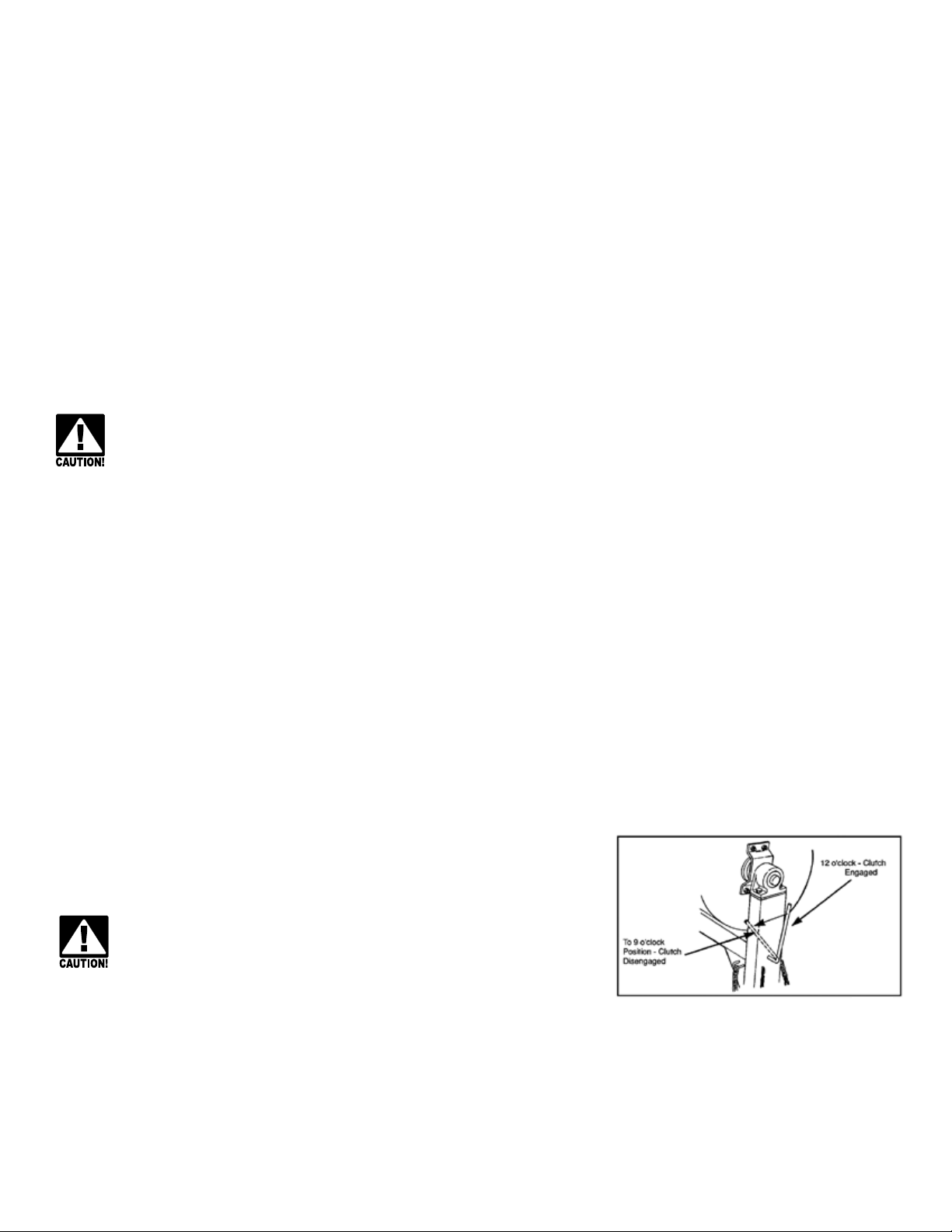
CLUTCH CONTROL LEVER
This control is located in front of the mixing drum on the mixer leg. (See Figure 2.)
This control engages and disengages the drive to the mixing blades
To avoid personal injury, this control must be disengaged before
starting engine/motor or when mixer is not in use.
Figure 2
TO ENGAGE: Position lever in line with the mixer frame (12 o’clock position). Lever is held in the engage position by the
over-center action of the linkage.
TO DISENGAGE: Push lever down (counter-clock-wise) to the 9 o’clock position. Lever is spring loaded to hold it in the
disengaged position.
6 of 22
Page 7

OPERATING THE MIXER
STARTING THE MIXER
To avoid personal injury, be sure control lever is in the neutral position before starting engine/motor
Start the mixer engine/motor. Refer to the engine/motor manual for proper starting procedures. When the engine/motor is
warmed up and is running smoothly, move the control lever to the neutral position.
EXTENSION CORDS FOR ELECTRIC MOTORS
The following size extension cords should be used: length of cord, up to 100 ft.-14 gauge wire; up to 200 feet-12 gauge wire;
up to 300 feet-10 gauge wire; up to 400 feet-8 gauge wire.
NOTE: Extension cord must be a 3-wire power cord and 3-wire power plug that is approved for outdoor use. When
connecting the power cord, always connect cord to motor first and then plug into a grounded receptacle. When
disconnecting the power cord, always unplug the grounded receptacle first.
LOADING THE MIXER
When the mixing blades are rotating, pour the required amount of water into the drum, then add cement, sand and lime or
mortar mix. The desired mixing speed is 33 RPM.
To avoid personal injury, be sure grill assembly is down an in place when mixer is in operation
To avoid personal injury, be sure drum is locked in the operating position
DISCHARGING THE MIXER
Allow the entire mixture to mix for one (1) full minute. DO NOT STOP MIXER FROM ROTATING. Hold the tilt handle and
disengage the drum lock. Dump mortar to the side by pulling the tilt lever downward. After the mixture is dumped, return
the drum to the operating position and engage drum lock.
CLEANING THE MIXER
To achieve satisfactory performance from the mixer, it is essential to give the drum reasonable care. Clean the mixer after
each use, before the mortar dries and becomes hard. Never permit mortar to harden on either the inside or outside of the
drum. Do not pound or dent the drum as this impairs mixing efficiency and can cause spot wear on the drum surface. Spray
the entire unit off after each use.
To avoid personal injury, always turn engine/motor off and wait for all motion to stop before cleaning.
CARE OF MIXER
It is important to keep the inside of the mixing drum free of hardened mortar. After discharging the last batch of mortar each
day, add a pailful of water and two shovelfuls of gravel to the drum. This will scour the inside of the drum. Mix for about two
minutes, discharge and rinse the drum with water.
7 of 22
Page 8

OPERATING GUIDELINES
MASONRY CONSTRUCTION GUIDELINES
The strength and durability of brick masonry depends upon the quality of the brick, the quality of the mortar and the
workmanship in laying. The strength also depends upon adequate bond and the shape of the masonry unit.
Brick quality – Characteristics are hardness and density. Brick for masonry which is exposed to weather or where strength
is desired should have a crushing strength of not less than 2500 PSI.
Laying and bonding – Brick should be laid in a full bed of mortar and shoved laterally into place to secure solid bearing, a
bed of even thickness, and to fill the vertical joints. Brick should be thoroughly wet before laying, except in freezing weather.
Bricks laid with the long dimension parallel to the face of the work are called stretches, perpendicular to the face are called
headers. Bats (chalk bricks) should not be used except where necessary to make corners or to form patterns on the face of
the walls. Walls are bonded or tied together longitudinally by overlapping stretches in successive courses. Transverse bond
is obtained by making every sixth course headers with the headers themselves overlapping in successive courses in the
interior of thick walls.
Mortars – Mortar composition is dependent on the structural use of the masonry unit. It is also dependent upon grade,
weather exposure and climactic condition. Consult you brick or block supplier, the ACI (American Concrete Institute) Manual
of Concrete Practices or your local building codes for the proper mortar selection for each application form more information.
LUBRICATION
To avoid personal injury, always turn off engine/motor and wait for all motion to stop before making
adjustments or repairs
DRUM SEAL HOUSINGS
Drum seals are provided on each end of the drum where the mixing shaft passes through to the bearings. It is important to
pump grease into the housings through use to retain seal efficiency. Use enough grease to flush out old grease and carry
away any grit. Use lithium based grade 2 multi-purpose grease. SEE FIGURE 3
MIXING SHAFT BEARINGS
The mixing shaft bearings are permanently factory sealed and lubricated, and should
not require further service.
WHEEL BEARINGS
Wheel bearings should be packed once a year. Thoroughly clean old lubricant from the
bearings, hub and spindles before repacking. Pack bearings only one-half to two-thirds
full with grease to prevent overheating. Use no. 2 wheel bearing grease.
DRUM SHAFT BEARING HANGERS
Drum yoke bearing hangers are located on each side of the drum, and are equipped
with grease fittings. These bearings should be lubricated once each week with lithium based grade 2 multi-purpose grease.
ENGINE/MOTOR
Refer to the engine/motor operating instructions for all maintenance and lubrication instructions and requirements.
JACK SHAFT BEARINGS
Pillow block style bearing are used on the drive train counter-shaft. See Drum Seal Housing, Lubrication Guidelines for
more information. See Figure 4 for bearing locations.
8 of 22
Page 9

ADJUSTMENT
To avoid personal injury, always turn off engine/motor and wait for all motion to stop before making
adjustments or repairs
RUBBER WIPER BLADES
Adjust rubber wipers so they fit snugly against the drum but not to the point that they fold over when the blades rotate.
ENGINE/MOTOR DRIVE
SEE FIGURE 4.
1. Align pulleys correctly
2. Tighten locking collars in the direction of rotation and
tighten setscrews.
3. Adjust tension on the engine belt as follows:
A. Place clutch lever in the engaged (drive) position.
B. Move the engine/motor to tighten the belt until the
engine plate is slightly above the horizontal
position (about 1-2 degrees). Tighten engine/
motor securely.
4. Adjust belt fingers so they do not touch the belt when the drive is engaged, but must allow disengagement of the belt
when the drive is disengaged.
5. Adjust bull gear for minimum clearance of 3/16 inch from the pillow block stand and tighten both setscrews.
STORAGE
For short term storage, clean the mixer and store in a dry place. If the mixer is not to be used for an extended period of
time, service the mixer completely and store in a dry place.
1. Refer to the engine/motor instructions for storage instructions.
2. Cover exposed metal surfaces with a thin coat of SAE 30 weight engine oil.
3. Lubricate per instructions outlined in the LUBRICATION section.
9 of 22
Page 10

FIGURE 5: DRUM AND DRIVE
10 of 22
Page 11

FIGURE 5: DRUM AND DRIVE
REF # NAME PART# QUANTITY
1 Bearing Hanger MIX232444 2
2 Grease Fitting MIX1031 4
3 Gear (Gasoline Powered Models) MIX232478 1
3 Alt Gear (Electric Powered Models) MIX245498 1
4 Drum Shell Assembly MIX245466 1
5 Grill Assembly MIX245459 1
6 Bearing Support Assembly MIX232459 2
7 Drum Tilt Lever MIX5126 1
8 Drum Seal MIX232465 2
9 Seal Housing MIX5095 2
10 Seal Retainer MIX5097 2
11 Shaft Seal MIX232573 2
12 Bearing, Drum Shaft (comes w/232463) MIX232462 2
13 Drum Shaft MIX245477 1
14 Locking Collar MIX232463 2
15 Capscrew, Hex Hd 1/2-13 x 1 1/2 Gr. 5 *MIX70343 4
16 Capscrew, Flat Hd 3/8-16 x 1 1/4 *MIX70430 8
17 Capscrew, Hex Hd 1/4-28 x 1 GR 5 *MIX71264 6
18 Capscrew, Hex Hd 3/8-16 x 2 Gr 5 *MIX70258 2
19 Nut, Hex 1/2-13 *MIX70563 4
20 Nut, Hex 3/8-16 *MIX70553 18
21 Washer, 3/8 Spring Lock *MIX70649 20
22 Washer, 1/2 Spring Lock *MIX70655 4
23 Washer, 1/4 Spring Lock *MIX70643 6
24 Key, Square 3/8 x 3 *MIX71023 1
25 Setscrew, Sq Hd Cup Pt 1/2-13 x 1 1/4 *MIX70069 1
26 Setscrew, Sq Hd Cup Pt 1/2-13 x 1 1/2 *MIX70074 1
27 Capscrew, Flat Hd 38-16 x 1 *MIX70429 8
28 Nut, Cone Lock 3/8-16 *MIX70631 2
29 Grip, Drum Tilt Lever MIX233160 1
30 Capscrew, Hex Hd 3/8-16 x 1 *MIX70235 1
31 Capscrew, Hex Hd 3/8-16 x 2 12 Gr 5 *MIX70266 1
* Common hardware, can be purchased locally.
11 of 22
Page 12

FIGURE 6: MIXING BLADES
12 of 22
Page 13

FIGURE 6: MIXING BLADES
REF # NAME PART# QUANTITY
1 Mixing Arm Assembly, Engine End MIX245460 2
2 Mixing Arm Assembly, Tow End MIX245463 2
3 Mixing Arm Cap MIX245461 4
4 Drum Wrap Wiper MIX5585 4
5 Wrap Wiper Backing Plate MIX5643 4
6 End Wiper Backing Plate MIX5088 2
7 Drum End Wiper MIX5089 2
8 Capscrew, Hex HD 5/8-11 x 2 Gr 5 *MIX71195 10
9 Capscrew, Hex HD 3/8-16 x 1 1/2 Gr 5 *MIX70249 16
10 Nut, Hex 5/8-11 *MIX70567 10
11 Nut, Hex 3/8-16 *MIX70553 20
12 Washer, 5/8 Spring Lock *MIX70657 10
13 Washer, 3/8 Spring Lock *MIX70649 20
14 Side Arm Assembly, Tow End 245465 1
15 Side Arm Assembly, Engine End 245464 1
16 Capscrew, Hex HD 3/8-16 x 1 3/4 Gr 5 *MIX70254 4
17 Washer, 3/8 Flat *MIX 70703 20
* Common hardware, can be purchased locally.
13 of 22
Page 14

FIGURE 7: ENGINE HOUSING
14 of 22
Page 15

FIGURE 7: ENGINE HOUSING
REF # NAME PART# QUANTITY
1 Engine Housing Assembly w/decals MIX245471 1
2 Housing Base Assembly MIX245470 1
3 Reflector MIX32082 2
4 T-Handle Latch MIX232623 2
5 Handle, Engine Housing MIX5402 1
6 Rivet, Handle MIX220521 4
7 Rubber Bumper MIX223590 4
8 Housing Base Front Plate MIX232614 1
9 Screw, Thread Forming 5/16-18 x 1/2 MIX213297 6
10 Screw, Sheet Metal #10-24 x 3/8 *MIX29065 4
11 Axle Assembly MIX232489 1
12 Hub Assembly (includes:) MIX38565 2
13 Bearing Cup MIX1046 4
14 Bearing Cone MIX1045 4
15 Hub Cap MIX5037 2
16 Lug Nut MIX38567 10
17 Seal MIX19981 2
18 Spring, Suspension MIX232496 2
19 Wheel and Tire Assembly MIX232385 2
Wheel MIX232386 2
Tire, A78-13 MIX232387 2
Valve Stem w/cap MIX10631 2
20 Capscrew, Hex Hd 1/2-13 x 1 1/2 Gr 5 *MIX70343 12
21 Capscrew, Hex Hd 5/16-18 x 3/4 Gr 5 *MIX70143 6
22 Nut, Hex 1/2-13 *MIX70563 12
23 Nut, 5/16-18 KEPS *MIX70942 4
24 Nut, Hex 10-24 KEPS *MIX70610 4
25 Screw, Rd Hd Machine 10-24 x 1/2 *MIX70386 4
26 Washer, 1/2 Spring Lock *MIX70655 12
27 Washer, 5/16 Spring Lock *MIX70646 2
28 Washer, 5/16 Flat *MIX70701 10
29 Pin, Cotter 1/8 x 1 3/4 *MIX71007 2
30 Nut, Hex Castle 3/4-16 *MIX70620 2
31 Washer, 3/4 Flat *MIX70713 2
32 Bracket, Spring Mount RH MIX245550 1
33 Bracket, Spring Mount LH MIX245549 1
* Common hardware, can be purchased locally.
15 of 22
Page 16

FIGURE 8: FRAME, DRIVE & CLUTCH CONTROL
16 of 22
Page 17

FIGURE 8: FRAME, DRIVE & CLUTCH CONTROL
REF # NAME PART# QUANTITY
1 Frame, Engine and Drive Support MIX245450 1
2 Frame Assembly MIX245201 1
3 Pin and Chain Assembly MIX232276 1
4 Pin, Cotter 3/16 x 1 *MIX70731 1
5 Spring Clip *MIX2776 1
6 Tow Pole Assembly Pintle (std) MIX239764 1
7 Capscrew, Hex Hd 1/2-13 x 3 1/4 Gr 5 *MIX71224 1
8 Handle, Drum Lock MIX245426 1
9 Grip Handle 1/2” (Upper) MIX36282 1
9 Grip Handle 5/8” (Lower) MIX750P40278 1
10 Capscrew, Hex Hd 1/2-13 x 1 1/2 Gr 5 *MIX70343 1
11 Nut, 1/2-13 Jam *MIX70581 1
12 Setscrew, Sq Hd 1/2-13 x 3 *MIX70068 1
13 Washer, 1/2 Flat *MIX70707 1
14 Shaft, Pinion (Gasoline Models) MIX245469 1
14 Shaft, Pinion (Electric Models) MIX245499 1
15 Gear, Pinion (Gasoline Models) MIX245468 1
15 Gear, Pinion (Electric Models) MIX5124 1
16 Bearing, Pillow Block (Gasoline Models) MIX232421 2
16 Bearing, Pillow Block (Electric Models) MIX5082 2
17 Key, 3/8 Sq x 2 *MIX71022 1
18 Setscrew, Soc Hd 5/16-18 x 1/4 Cup Pt *MIX70498 4
19 Pulley, Driven (see ref #18, Fig 9)
20 Shaft, Clutch Control MIX245457 1
21 Link, 3/8 and 5/8 holes MIX245264 1
22 Link, 3/8 and 1/2 holes MIX245328 1
23 Link, Clutch 6 inch MIX245298 1
24 Pin, 3/16 x 1 3/8 Roll *MIX70981 2
25 Clutch Rod subassembly MIX245316 1
26 Roller, Clutch MIX211689 1
27 Washer, 7/16 Flat *MIX70705 2
28 Spring, Overcenter MIX232266 1
29 Capscrew, Hex Hd 1/2-13 x 2 Gr 5 *MIX71194 4
30 Nut, 3/8-16 MIX70553 1
31 Nut, 1/2-13 *MIX70563 9
32 Nut, 1/2-13 Lock *MIX70631 2
33 Washer, 3/8 Spring Lock *MIX70649 2
34 Washer, 1/2 Flat *MIX70707 8
35 Clamp, Frame MIX245338 2
36 Washer, 1/2 Spring Lock *MIX70655 8
37 Capscrew, Hex Hd 3/8-16 x 1 3/4 Gr 5 *MIX70254 2
* Common hardware, can be purchased locally.
17 of 22
Page 18

FIGURE 9 ENGINE MOUNT
18 of 22
Page 19

FIGURE 9 ENGINE MOUNT
REF # NAME PART# QUANTITY
1 Frame, Engine and Drive Support MIX232412 1
2 Frame Assembly MIX245339 1
3 Pin and Chain Assembly *MIX70631 1
4 Pin, Cotter 3/16 x 1 *MIX70687 1
5 Spring Clip MIX232548 1
6 Tow Pole Assembly Pintle (std) *MIX70258 1
7 Capscrew, Hex Hd 1/2-13 x 3 1/4 Gr 5 *MIX70553 1
8 Handle, Drum Lock *MIX70649 1
9 Grip Handle *MIX23156 2
10 Capscrew, Hex Hd 1/2-13 x 1 1/2 Gr 5 *MIX71404 1
11 Nut, 1/2-13 Jam *MIX70803 1
12 Setscrew, Sq Hd 1/2-13 x 3 *MIX70498 1
13 Washer, 1/2 Flat *MIX70451 1
MP1200 MODEL 59328
14 Engine, Honda GX240HA 8 HP MIX245200 1
15 Engine Mount Plate MIX245400 1
16 Belts (set of 2) MIX245723 1
17 Pulley, Drive 3 3/8 O.D. MIX245721 1
18 Pulley, Driven 8 3/4 O.D. MIX245722 1
19 Capscrew, Hex Hd 5/16-18 x 1 3/4 Gr 5 *MIX70170 4
MP1200 MODEL 59334
14 MOTOR, 3 HP #5K675 MIX5328 1
MOTOR MOUNTING ADAPTER (NOT SHOWN) MIX245496 1
15 MOTOR MOUNT PLATE MIX245449 1
16 BELTS (SET OF 2) MIX5115 1
17 PULLEY, DRIVE 3 IN. O.D. MIX5118 1
18 PULLEY, DRIVEN 13 3/4 O.D. MIX5121 1
19 CAPSCREW, HEX HD 5/16-18 X 1 3/4 GR 5 *MIX70170 4
ADDITIONAL ENGINE MOUNT HARDWARE -SEE REF. 19 FOR CORRECT SIZE
20 WASHER, 3/8 FLAT *MIX70703 4
WASHER, 5/16 FLAT *MIX70701 4
21 WASHER, 3/8 FLAT THICK 7/8 O.D. *MIX15589 4
22 WASHER, 3/8 SPRING LOCK *MIX70649 4
23 NUT, HEX 3/8-16 *MIX70553 4
NUT, HEX 5/16-18 KEPS *MIX70942 4
* Common hardware, can be purchased locally.
19 of 22
Page 20

TROUBLE SHOOTING GUIDE FOR MP MIXERS
ENGINE WON’T START:
1. Check for sufficient fuel.
2. Check oil level (some engines have an oil alert, preventing the engine from starting when oil level is low)
3. Was engine choked when starting?
4. Is engine flooded?
5. Check spark plug. (Clean and check gap).
6. If engine still won’t start, take to service center.
BELT DRIVEN MODELS:
1. Check condition of belts, replace if necessary.
2. Check for oil or grease on belts as well as for loose belts.
3. Adjust set screw under engine base down until belts are tight.
HYDRAULIC DRIVEN MODELS.
PADDLE ARMS WON’T TURN:
1. Check if clutch rod has been bent or broken.
2. Check if flow control valve moves in forward position.
IF VALVE DOES NOT GO INTO FORWARD POSITION CHECK THE FOLLOWING:
1. Check if linkages are free.
2. Remove stem set screw (Fig 1) and put a few drops of oil in stem.
3. Replace set screw but do not overtighten.
PADDLE ARMS STOP WHEN DRUM IS FILLED:
1. Remove cap (Fig 2) and set pressure up by tightening threaded screw with allen wrench no more than ¼ turn at a time.
Valve pressure is set at 1500 psi at factory. Each ¼ turn will increase the pressure by 250 psi. After each ¼ turn check to
see if paddles turn (CAUTION) maximum pressure of valve is 3000 psi.
REVERSE TOO FAST OR TOO SLOW:
1. Loosen set screw on knob
2. Turn knob a small amount at a time clockwise to slow movement and
counterclockwise to speed up movement
20 of 22
Page 21

21 of 22
Page 22

104 S. 8th Ave.
Marshalltown, IA
Phone 800-888-0127 / 641-753-0127
Fax 800-477-6341 / 641-753-6341
www.marshalltown.com
22 of 22
 Loading...