

Page 1
Broadcast A/V Division
V-R241-4K
12G-SDI / HDMI Multi Format LCD Monitor
User Manual
Page 2
V-R241-4K Manual
Table of Contents
1. Introduction
2. Features
3. Front Panel Features
4. Rear Panel Features
5. Compatible Input Formats
6. Main Menu and Navigation
7. Marker Config
8. Video Config
9. Color Config
10. Audio Config
11. On-Screen Features
12. Waveform Config
13. Caption Config
14. Time Code Config
02
02
03
04
05
06
08
09
11
12
14
15
16
17
1. Introduction
Welcome to the Marshall V-R241-4K multi-format monitor. This feature-rich design supports
video formats up to 4K/UHD, wide color gamut, HDR calibration and much more. Video inputs
include 12G SDI, quad 3G SDI and HDMI 2.0. Special features include quad display mode, IMD
text and tally, timecode display, 16-channel audio bars, waveform monitor, vectorscope and
programmable function buttons.
2. Features
• 2 - 12G SDI Inputs for 12G / 3G / HD SDI with looping outputs. Accepts up to 4K / UHD
• 2 - 3G SDI Inputs add Quad 4K/UHD, 2SI 4K/UHD and Quad View capabilities
• 1 - HDMI Input accepts up to 4096 x 2160p and 3840 x 2160 (4K/UHD)
• Waveform & Vector Scope (on SDI inputs)
• Time Code, Closed Caption and IMD displays
• Audio De-embedder & Internal Speaker + Headphone Jack for Confidence Monitoring
• Up 16 Channel Audio Level Meter Display
• Picture Flip / Mirror Modes
• 3D LUT Presets Including: BT.709 / SMPTE-C / EBU / NTSC / D-Cinema .
15. IMD Config
16. OSD
17. System Config
18. Communication Config
19. Control Config
20. Service Config
21. Specifications
22. Dimensions
Warranty
18
19
20
22
24
26
27
28
29
• Adjustable Backlight
• RS-232, RS-422, Ethernet and GPI control ports
• LED and on-screen tallies
• USB port for easy field updates
www.marshall-usa.com1 2
Page 3
V-R241-4K Manual
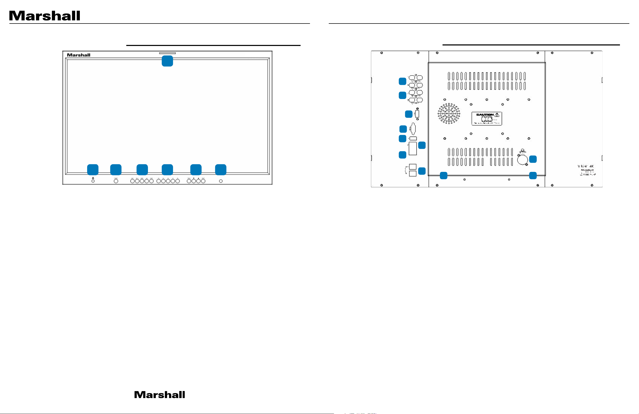
3. Front Panel Features
6
1 2 3 4 5
4. Rear Panel Features
7
1
2
3
4
5
6
7
8
9 9
10
1. Power Button
Use the Power button to toggle the monitor
between ON and STANDBY modes.
2. Input Select Buttons
Directly switch between input source and type,
Choices are: SDI 1, SDI 2, QUAD, 2SI and HDMI.
3. User-definable function buttons
Five user-definable function buttons F1-F5 can
be used for direct access to various settings.
Functions are assigned through the menu system.
Current aspect ratio selection.
4. Menu/Down/Up/Input
Menu: Enter or exist Main Menu.
Up: Move up or increase parameter values.
Down: Move down or decreases parameter
values.
Input: Acts as Enter Key for menus or selects.
Video source when not in menu mode
Press and hold Input button for 5 seconds to
display current monitor status including…
• Input source and video format
• Current white balance / color temperature
• Audio source monitored currently
• Current aspect ratio selection
5. Adjustment Knob
Provides quick access to Volume, Back light
Adjust, Brightness, Saturation, Tint, and Contrast
of the image. Press in on knob to activate, turn
knob to select, press knob again to confirm. Also
use in Menus.
6. Headphone Output
Stereo 3.5mm jack allows monitoring two
channels of audio from SDI or HDMI sources.
Plugging headphones in will mute the built-in
speakers.
7. Tally LED
Three color LED tally lights (Green/Red/Amber)
are available above the screen. These are
operated by GPI (contact closure) or IMD control
protocol.
1. Two 12G-SDI inputs / outputs
Two 12G-SDI inputs with active loop-through out.
2. Two 3G-SDI Inputs / outputs
Two additional 3G-SDI inputs support Quad 4k,
2SI 4K and Quad View Modes.
3. HDMI Input
HDMI Input Connector.
4. Serial / RS-232
For remote operation monitor calibration, etc.
5. USB Port
Firmware Upgrade port.
6. GPI (General Purpose Interface)
This dual purpose connector may be used
to trigger LED Tally Lights and trigger preset
functions.
7. Ethernet
Ethernet port for remote operation.
8. UMD/IMD RS-422 IN/OUT
The RS-422/485 port is used to control the IMD
(In Monitor Display) features compatible with TSL
Tally Man and Image Video. The second port can
be used to loop multiple monitors in the same
bus.
9. Speaker Outputs
Ethernet port for remote operation.
10. Ethernet
Connect the 5-pin XLR power input here.
Power should only be supplied from the included
power supply.
www.marshall-usa.com3 4
Page 4
5. Compatible Input Formats 6. Main Menu and Navigation
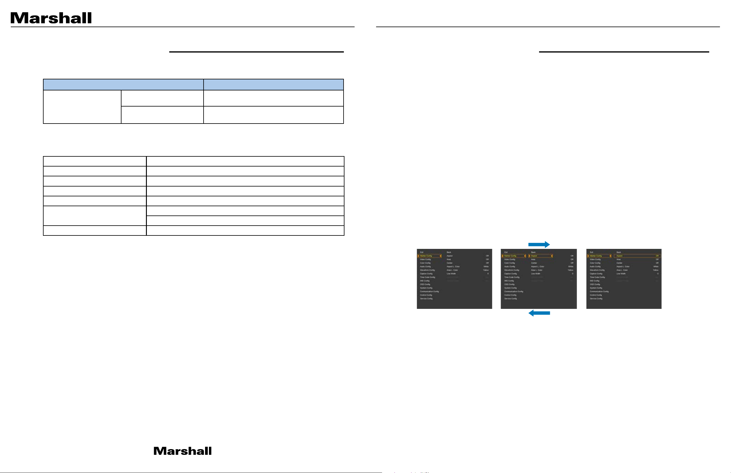
The following video standards are supported by the V-R241-4K monitor: The menu system provides many choices to customize the monitor operation. Most menus
consist of just three levels to set up the options, but some require greater depth for the variety
Supported
Signals
Items Specifications
Serial Digital Interface
HDMI
12G, 3G, HD SDI (SMPTE ST-2082/SMPTE 425 /
295M / 292 / 296)
720p / 1080p / 2160p
of settings available. When the MENU button is pressed, only the first and second level of the
menu system will appear on the screen. The third level can be displayed by pressing SEL/
INPUT. If a menu has more than three levels, a pop-up dialogue box will be displayed as the
fourth or fifth level.
Menu ON/OFF
V-R241-4K Manual
SDI Input Detail
SMPTE ST 2082
SMPTE-428.1M
SMPTE-425M(3G)
SMPTE-260M
SMPTE-259M
SMPTE-274M
SMPTE-296M
3840 x 2160 (50/59.94/60p), 4096 x 2160 letterbox
2048 x 1080P (23.98/24)
1920 x 1080P (Level A & B)
1920 x 1035i (60/59.94)
1920 x 1080i (50)
1920 x 1080i (50/59.94/60)
1920 x 1080P (30Psf/25Psf/24Psf/30/25/24)
1280 x 720P (24/25/30/50/59.94/60)
Press the MENU button to display the menu. A second press of the MENU button will return to
normal viewing.
When the MENU is on screen, use the Up / Down buttons or turn the Adjust Knob to move from
item to item.
To go to the next level
Press SEL/INPUT button or press the Adjust Knob.
To go back to the previous level
Press MENU button or select the Back menu choice.
Powering the Monitor
When power is first applied to the monitor, it will enter Power On mode (power LED is Green) and
return to the operational mode it was in prior to power being removed.
Press the Power button to put the monitor into Standby eco mode (power LED is off).
Press the Power button again to put the monitor back into Power On Mode.
Volume Adjustment
Press the Adjust Knob. Volume will appear as the first option, turn the knob to change the
volume.
Suggestion: It is often convenient to have a quick way to MUTE the audio quickly without turning
a knob. This can be accomplished by programming MUTE to one of the Function buttons (F1…
F5). (See Control Config section below).
www.marshall-usa.com5 6
Page 5
V-R241-4K Manual
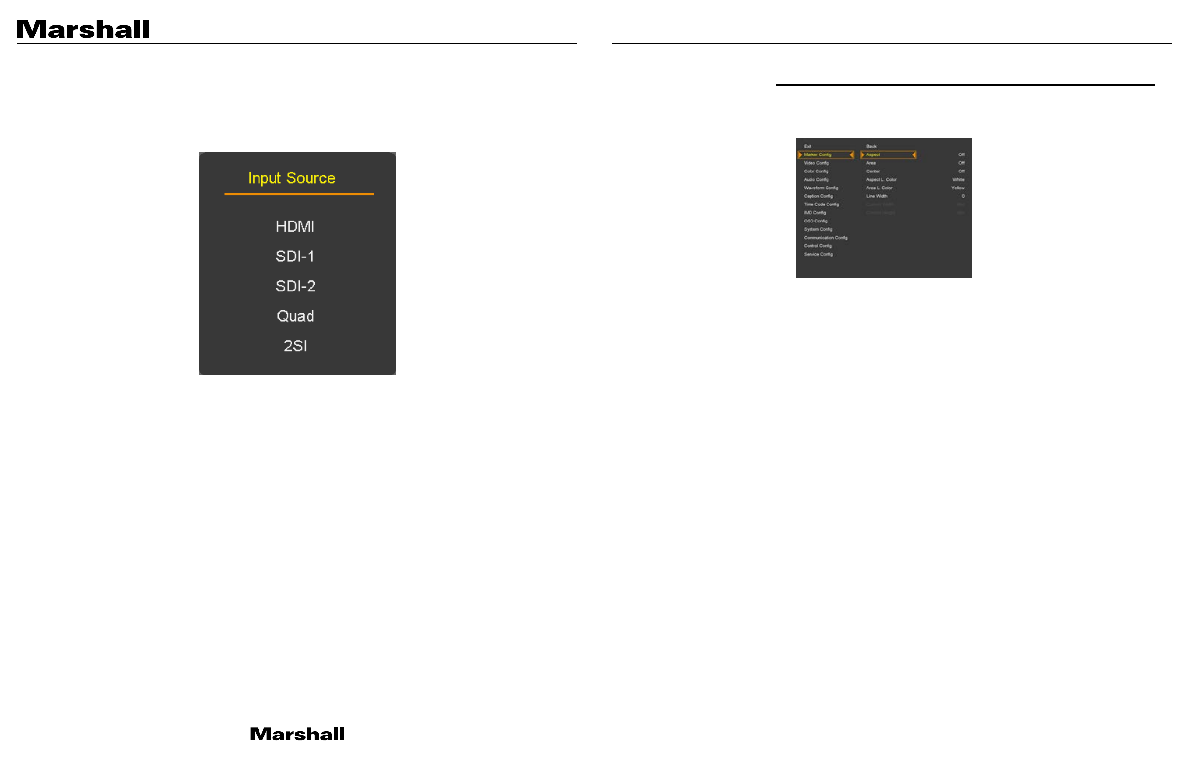
Selecting a Video Source
Press one of the input direct access buttons (just to the right of the Power button) or…..
Press the INPUT button and then use UP/DOWN arrows or turn the Adjust Knob to highlight
the desired source, then press INPUT or the Adjust Knob to complete the selection.
7. Marker Config
The Marker Config item allows selection of on-screen markers for Aspect Ratio, Center Mark as
well as “safe action” and “safe area” type borders.
Aspect
Preset marker borders are available for these aspect ratios: Custom, 16:9, 4:3, 14:9, 13:9, 1.85:1,
2.35:1, 1:85/4:3. When Custom is selected, scroll down to Custom Width and Custom Height to
create the desired marker.
Press and hold the INPUT button for 5 seconds to see current monitor status.
Note: 4K / UHD may be input several ways:
Single cable 12G SDI to either SDI-1 or SDI-2.
Single cable HDMI to HDMI input, must conform to HDMI 2.0 spec.
Four cable in either Quad or 2SI formats to SDI- 1, 2, 3 & 4.
Two cable Dual 6G not supported.
Also, the monitor can accept four different sources, “Quad Viewer” style. Used this way, all
sources must be synchronous, 1080p and same frame rate.
Area
The Area setting creates a dotted-line marker showing picture area reductions by percentage:
• 16:9 format choices: 95, 93, 90, 88, 85, 80% (set as desired for safe action/safe title)
• 4:3 format choices: 95, 93, 90, 88, 85, 80% (set as desired for safe action/safe title)
• EBU Action choices: 16:9, 14:9, 4:3 (EBU recommendations for safe action)
• EBU Graphic choices: 16:9, 14:9, 4:3 (EBU recommendations for safe title)
Center Marker
Turns on a “+” Marker in center of screen.
Aspect L. Color
Selects color for Aspect marker (solid border). Choices are: WHITE, YELLOW, BLUE, RED,
BLACK.
Area L. Color
Selects color for Area marker (dotted line border). Choices are: WHITE, YELLOW, BLUE, RED, BLACK.
Line Width
Provides adjustment of the marker line thickness. Range is 0 - 10.
Custom Width and Custom Height
These setting options appear when Aspect has been set to Custom.
www.marshall-usa.com7 8
Page 6

V-R241-4K Manual
8. Video Config
The Video Config setting provides control of a wide range of display functions and picture
adjustments.
Aspect Ratio
The Aspect Ratio setting changes the way the width and height of the image is displayed on
the monitor
Choices are: Full screen (the image is presented using all pixels in the display).
Or preset aspect ratios of: 16:9, 4:3, 14: 9, 13:9, 1.85:1, 2.35:1, Pixel.
“Pixel” means “Pixel-to-Pixel” mode where each pixel in the source image is mapped 1:1 to
a pixel on the screen. The is the same as “no scaling”. In this mode, a 1920 x 1080 image, for
example, will not fill the screen but will instead fill only the 1920 x 1080 pixel area in the middle
of the screen. A 720p image will be smaller still.
IMPORTANT NOTE: Aspect ratio choices are stored for each input format, they are not global.
For example, setting the Aspect ratio to 4:3 while a 720p source is being displayed will affect
only 720p sources.
HV Delay (SDI Only)
The video image can be shifted on the display horizontally (to the right), vertically (shifted
down) or both (sometimes called “pulse cross” mode). This allows inspection of the Horizontal
Ancillary Data (HANC) and Vertical Ancillary Data (VANC) spaces. Additional data such as audio,
timecode, closed captioning, AFD and other information is embedded in these blank areas and
transported along with the video.
Choices available are: Off (no shift), H (shift right), V (shift down), H+V (both).
NOTE: Despite the names, VANC appears on screen as the horizontal strip at the top of the
image and HANC appears as the vertical bar to the right of the image.
Peaking Filter
The Peaking Filter function adds color to the sharpest details in the video image. This is intended
as an aid in adjusting best focus in video cameras. Choices are:
Peaking Filter On/Off – Switch this function ON or OFF.
Peaking Color – Select the color that is overlayed on picture details. Select Red, Blue, White,
or Violet.
Peaking Level – Adjust the amount of color that appears on the image detail. Range is 0 to 100.
False Color
The False Color function adds color to regions in the video image based on Luma level. This is
intended as a quick way to compare portions of an image or to warn if levels from a video source
are too high or too low. A colored strip to the right of the image shows the level that each color
represents.
NOTE: As an alternative, the Waveform Monitor function serves the same level measurement
purpose with more precision but without identifying specific regions of an image.
Gamma Select
This setting selects the way the monitor will reproduce contrast “gray scale”.
Adjustment is continuously variable from 0.80 to 3.00 in steps of 0.10. From 2.30 to 2.40 the
steps are 0.05.
Common choices are 2.2 (reciprocal of camera gamma setting of 0.45) or 2.4 (mimics gamma of
average color CRT which may be useful when viewing material originally color balance to CRT
reference).
Color Only
This allows setting the monitor to Mono (black and white mode) or Blue Only to provide a quick
check of Color and Tint settings when using standard color bars as a source.
HDR Mode
The HDR Mode supports modern High Dynamic Range technology which allows extended
contrast, color saturation, and gamut. Choices are:
ST 2084-300 / ST 2084-1000 / ST 2084-10000 “Perceptual Quantizer” function to reproduce
PQ HDR video mastered for 300, 1000, or 10,000 Nit displays.
HLG “Hybrid Log Gamma” combines standard Gamma with extended white and specular levels
for HLG mastered HDR video.
HDR Demo ON / OFF (Enhances color of Standard Dynamic Range image to simulate HDR).
www.marshall-usa.com9 10
Page 7

V-R241-4K Manual
9. Color Config
Back Light
This setting allows adjustment of the backlight of the LCD panel. This is typically set based upon
ambient room lighting and/or as part of a monitor calibration. Range is: 0 – 100. Default is: 50
Brightness, Contrast, Color, Tint and Sharpness
Adjust the values of Brightness, Contrast, Color, Tint and Sharpness directly from 0 to 100.
Default is: 50
Contrast, Brightness, Sharpness, Color – allow calibration of monitor to normal viewing
standards.
Color Space (Color Gamut)
Color Space presets are provided to allow best reproduction of material acquired or color
corrected for a particular color gamut. Choices are: Native / BT 709 (REC 709) / SMPTE-C /
EBU / NTSC / D-Cinema.
Native is the maximum uncalibrated gamut of the display.
Manual color balance settings (User)
Selecting USER for Color Temp allows manual calibration of white and black balance. The
adjustments consist of Red, Green, Blue GAIN and OFFSET. GAIN adjusts the overall level
(amplitude) of a single primary color. OFFSET adjusts the brightness (pedestal/offset) of that
color.
In practice, one of the above Color Temp presets is first selected (rather than USER), then Red
and Blue GAINS are adjusted to achieve a particular white balance (color temperature). Finally,
OFFSETS will need to be adjusted to create a neutral black color. It is normal to have to repeat
these steps until the desired effect is achieved.
NOTE: Adjusting all three colors in the same direction will result in a brighter or darker picture
with no color change, this is self-defeating. Adjustment range is: 0 – 255. Default for GAIN is
200, OFFSET is 128.
Tint – Tint can be adjusted for any input but the primary purpose is to correct subcarrier phase
errors created from Composite video sources (NTSC / PAL). Tint adjustment is not recommended
for digital sources as they do not possess subcarrier. The exception is when a source has been
converted from composite video and errors remain.
Sharpness – Enhances edges of image detail. To be used sparingly……
NOTE – SHORT CUT: This group of adjustments is available for quick access through the front
panel Adjust Knob. Press the Adjust Knob until the desired parameter shows up, then turn the
knob to make the adjustment.
Color Temp
Select one of the preset Color Temperature choices or make manual adjustment of RGB Gain
and Offset values.
Choices are:
Standard Presets of: 9300K, 6500K, 5400K, 3200K.
Special purpose LUTS: D65 (6504K), C (6674K), D-Cinema (6302K).
USER (See Manual Color Balance below).
VAR (Select from 3200K to 9300K in 100K steps) The most common selection for video work
is 6500K.
10. Audio Config
SDI Gr & SDI Ch (SDI sources only)
SDI inputs can carry up to 16 channels or 8 stereo pairs of digital audio embedded along with
the video.
The 16 audio channels are divided into 4 Groups of 4 Channels each.
SDI Gr provides selection of the desired audio Group for monitoring.
Choices are: Group 1 through 4
SDI Ch provides selection of the individual audio channels for monitoring.
Common settings used for other applications are: 9300K, 5400K, 3200K.
www.marshall-usa.com11 12
Page 8

V-R241-4K Manual
Choose from Channel 1 through Channel 16 or select OFF (silence). Channels may be monitors
individually or in pairs, 1&2, 3&4, etc.
NOTE: Short-cut. Program one of the User Buttons (F1 – F5) to “Audio Channel” for quick
selection of audio channels without opening the menu system. Seee Control Config section
below.
Level Meter Enable
Turning this function ON causes audio level meter “bars” to appear superimposed over the
picture.
Level meters are only available when monitoring SDI 1 or SDI 2 inputs or HDMI.
Level meters do not appear while the Menu is displayed on screen.
Type (SDI sources only)
Select the number of audio meter bars to be displayed.
Pair shows just a pair of audio meter bars typically representing Left and Right audio channels.
Group shows all four channels from a particular Group.
Level Meter Position
Select one of four meter display positions
11. On-Screen Features
The V-R241-4K monitor comes with several powerful on-screen display (OSD) features.
These include:
• Audio Meter Bars
• Waveform Monitor / Vectorscope display
• Closed Caption decode and text display
• Timecode decode and display
• IMD In Monitor Display of Tally and Text
Most of these may be used at the same time but there are limitations. Some will require position
adjustment to avoid overlap. Others use the same resources and cannot appear on-screen at
the same time.
These combinations may appear on-screen together:
• Timecode, Audio Bars, Waveform / Vector
• Timecode, Audio Bars, IMD
• Timecode, Audio Bars, Closed Caption
Scale Meter Scale
Provides selection of the desired audio meter scale and response mode.
Choices are: Digital (PPM), Nordic, BBC, EBU, DIN, Expanded DIN, SMPTE VU, EBU VU,
France VU
The most common setting is Digital.
Volume
Adjust the speaker or headphone Volume level here.
NOTE – SHORT CUT: This adjustment is available through the front panel Adjust knob. Press
the Adjust knob then turn the knob to make Volume adjustment.
These items will conflict:
• Waveform / Vector and Closed Caption
• Waveform / Vector and IMD
• Closed Caption and IMD
Note: A useful trick is to assign Waveform to one of the Function buttons (F1 – F5). Waveform /
Vector can be popped up when needed, interrupting IMD or Closed captioning only as long as
necessary. They will reappear when the Waveform Function button is pressed again.
www.marshall-usa.com13 14
Page 9

12. Waveform Config 13. Caption Config
V-R241-4K Manual
Enable
Selects Waveform Monitor & Vectorscope display.
NOTE: This feature is available only when an SDI input is selected. Waveform/Vector displays
do not appear when a menu page is on screen.
Format
Select one of several Waveform monitor / Vectorscope display modes.
Choices are:
Y (Most common mode – standard Luma Waveform display)
Cb, Cr Display only Cb or Cr color difference signal
Y+Cb+Cr Display Luma and color difference components side-by-side
G, B, R Display one color primary signal
G+B+R (Displays all three primaries in “parade view”, side-by-side)
Line
When this function is ON, the Waveform and Vectorscope will measure and display a single
line from the video input. The single line that is being displayed on the Waveform Monitor and
Vectorscope is highlighted in the picture as a white horizontal line. As the line number is changed,
this highlight will move up or down the screen. This can be useful during troubleshooting or
when it is desired to evaluate a particular area of an image.
Line Number select: Select video line to be displayed by the Waveform Monitor and Vectorscope.
The V-R241-4K monitor can decode and display a variety of Closed Captioning that may be
embedded in the video signal from the selected SDI input. NOTE: Closed captioning is never
embedded in HDMI signals.
It is possible for more than one type of captioning to be embedded in the same digital stream.
Unlike analog Closed Captioning that is found on “Line 21”, digital captioning is not bound to
a particular video line but, instead, is carried in the Ancillary Data space in the SDI stream.
Captioning that is not properly identified or does not conform to standards will not be decoded
and displayed by the monitor.
Caption
This selection turns caption decoding on and selects the type of captioning to decode.
Choices are: 608 Transcoded (original style that has been converted to 708 style)
708 (advanced style that was introduced with HDTV)
608 Caption
There are several sub-modes within the Closed Captioning standards that allow for multiple
languages and text that is not captioning.
Choices are: C/C1, C/C2, C/C3, C/C4 In most cases, the primary captioning will be found by
selecting C/C1. The other choices, if present, typically represent additional languages.
TEXT1, TEXT2, TEXT3, TEXT4 Text messages that are not captions.
OFF Turns off caption decoding.
Line display: OFF/ON/5 Sec Select how long the highlight indicator will remain on the picture
display.
NOTE: The best way to use this feature is to set Line Display to ON, then exit out of the Menu.
Use the Adjust Knob to move the white marker line up or down to select the exact line to be
measured. The line number appears on the Waveform monitor display.
708 Caption
This selection turns on 708-style caption decoding which can include animations, colors and
special fonts.
Choices are: Service 1 through Service 6. In most cases, the primary captioning will be found
by selecting Service 1.
www.marshall-usa.com15 16
Page 10

V-R241-4K Manual
14. Time Code Config
SDI video may carry up to two embedded copies
of Timecode. These correspond to Vertical Interval
Timecode (VITC) plus a digital representation of
analog Longitudinal Timecode (LTC).
Enable
This selects which type of timecode will be decoded
and displayed. Timecode that is corrupted or does
not adhere to SMPTE standards will not be displayed.
Choices are: OFF, LTC, DVITC
NOTE: Timecode decoding is available from SDI inputs only.
Size
This selection changes the size of the displayed timecode characters.
Choices are: Small, Middle, Large
15. IMD Config
IMD stands for “In Monitor Display” and consists of
large font text which can represent a source name,
a person’s name, or other arbitrary text. In this
monitor, IMD text may be input manually by the user
or electronically from an IMD/UMD controller such as
those from Image Video® or TSL®.
Manual Text Input Method
IMD
Turn IMD text display ON or OFF here.
NOTE: This item should be set to ON when when using manual or external IMD control however,
in most cases, Image Video control will turn it ON when text is sent.
See Communications Config section below for details.
Character (Manual IMD)
Position
This selection allows placing the timecode on screen where it will not interfere with the displayed
picture.
Choices are: L-T (left top), C-T (center top), R-T (right top), L-B (left bottom), C-B (center bottom),
R-B (right bottom)
Transparency
This selection affects the visibility of the Time Code display. At 0%, the video image is visible
through the Time Code characters. At 100%, there will be a black rectangle behind the characters.
Choices are: 0%, 25%, 50%, 75%, 100%
DVITC Line
Vertical Interval timecode may be embedded in any line in the SDI VANC (Vertical Ancillary Data)
space. There may be, in some cases, more than one VITC code embedded. The line location of
the VITC code may be selected here. Choices are:
• Auto The monitor will decode the first copy (lowest line number).
• Line 1 ~ 31 (manually select the line number to be decoded).
Use the front panel Adjust knob or arrow keys to type the desired manual (fixed) IMD message
up to 16 characters in length. IMD text appears in the bottom center of the display area.
FG Color & BG Color
Select the color of the IMD text (foreground) and background with these two items.
Numbers represent the amount of Red, Green and Blue to be mixed. 255 = maximum, 0 =
minimum.
For example, menu choice: (255, 0, 0) = Red Select Transparent = no color to make text invisible.
R G B R G B
Red 255 0 0 Dark Red 128 0 0
Green 0 255 0 Dark Green 0 128 0
Yello w 255 255 0 Dark Yellow 128 128 0
Blue 0 0 255 Dark Blue 0 0 128
Magenta 255 0 255 Dark Magenta 128 0 128
Cyan 0 255 255 Dark Cyan 0 128 128
White 255 255 255 Gray 192 192 192
Dark Gray 128 128 128 Black 0 0 0
www.marshall-usa.com17 18
Page 11

V-R241-4K Manual
16. OSD
This function controls the appearance of the OSD (On
Screen Display) menus.
Transparency
Sets whether the OSD menus have a black background
or are simply superimposed over the image.
Timeout
Sets how long the Menus will be on screen after menu
choices have been completed.
Choices are: ON OSD stays ON until manually turned off by pressing the Menu button.
5sec, 10sec, 20sec, 30sec, 40sec, 50sec, 60sec OSD menus disappear after the selected
number of seconds.
Input Format OSD
Sets how long the Input Format message remains in the upper left corner of the screen. Input
Format includes the name of the source currently in use, the video format and the video frame
rate.
Choices are: ON Input Format message remains on screen constantly
5sec The Input Format message appears on screen when a new source is selected and
disappears after 5 seconds.
OFF The Input Format message does not appear.
17. System Config
GPI Control & GPI#
GPI (General Purpose Interface) is the simplest type
of remote interface requiring only a button or switch
connected from one of the control pins on the GPI
connector to the Ground or Common pin. This type of
interface is sometimes called a “pull down”, or “contact
closure” interface. It is compatible with relay and “open
collector” outputs, for example from video production
switchers. Pins 1 - 6 on the GPI connector can each be
assigned to different functions. Pin 8 is the “ground” or
“common” pin.
NOTE: Pin 7 when triggered, operates the same as the front Power button. It will cycle the
power between Operate and Standby modes. Pin 7 cannot be assigned for other functions.
Functions that can be assigned to GPI triggers:
Tally R, Tally G: Turn Red or Green tally LED on. Turn both on for Amber tally (use two GPI’s for
Amber).
Marker On/Off: Toggle Aspect & Area markers on/off, does not change marker settings.
F1, F2, F3, F4 or F5: Same effect as pressing on the front panel button F1 through F5.
Aspect: Cycles through aspect ratio options. “Not available” will appear when video is not
connected.
Aspect Marker: Cycles through aspect ratio Marker options.
Area Marker: Cycles through Area Marker options.
Center Marker: Toggle Center “+” marker on/off.
Input SDI1, Input SDI2, Input Quad, Input 2SI, Input HDMI: Has same effect as pressing
these front panel buttons.
Menu Key, Enter Key, Up Key, Down Key, Left Key, Right Key: Has same effect as pressing
these front panel buttons.
H/V Delay: Cycles through four choices of OFF (no shift), H (Shift image left), V (Shift Image
down), H+V (both shifts).
Undefined: No function / disabled.
www.marshall-usa.com19 20
Page 12

V-R241-4K Manual
Factory Default
Sets the monitor menus back to Factory original settings. User settings will be erased.
Choices: ON reset to factory settings, OFF do not reset.
NOTE: Pressing the Adjust Knob or Input button initiates reset.
Fan Control
The internal cooling fan my be controlled through this function.
Choices are:
Auto: The fan turns ON as needed if the temperature is higher than the temperature set as
Active Temp (Celsius).
The fan turns OFF when the temperature drops by the amount shown as Hysteresis (1 – 10
degrees).
The monitor POWER will turn OFF if the temperature exceeds the amount shown in Shutdown.
ON: The fan runs constantly. Recommended when the ambient temperature is expected to be
high.
OFF: The fan will not run. This is not recommended except for short durations. For example, when
live audio is being recorded and the fan noise would be picked up by a microphone. Prolonged
operation with the fan forced OFF may lead to unwanted color changes in the displayed image
as well as reduced monitor life.
18. Communication Config
The Communication Config section provides settings for
three control interfaces:
LAN - Ethernet Network Port. General purpose control.
Capabilities depend on 3rd party control applications.
Can be used for IMD text, changing inputs and most other
parameters.
Serial - RS-232 Port. Primarily used with monitor
calibration applications.
422 - RS-422/485 Port for IMD and general purpose control. Capabilities depend on 3rd party
applications.
Set I.D (01~254)
Select the ID number for the serial ports. This ID number applies to both RS-232 and RS422/485 control connections. ID numbers must be in the range 1 to 254. 0 = OFF Assigning an
ID number is useful when more than one monitor or other device will be controlled on a shared
serial connection. Default ID number = 1.
Serial Baud Rate (RS-232 Port)
Select the Baud rate (data rate) for the RS-232 serial port.
Choices are: 2400, 4800, 9600, 19200, 38400, 57600, 115200 Default = 9600
IP Protocol
Select the protocol type for the Ethernet port. The protocol choice depends on the particular
controlling device.
Choices are:
Remcon (Remote Control).
TSL 5.0 – TSL Tallyman Version 5.0 (IMD Control).
TSL 4.0 – TSL Tallyman Version 4.0 (IMD Control).
NOTE: For IMD Control to operate via the Ethernet port set IMD to ON (see IMD Config section
above).
www.marshall-usa.com21 22
Page 13

V-R241-4K Manual
422 Baud Rate
Select the Baud rate (data rate) for the RS-422 serial port (Compatible with RS-485).
Choices are: 2400, 4800, 9600, 19200, 38400, 57600, 115200 Default = 38400
422 Protocol
Select the protocol type for the RS-422/485 serial port. The protocol choice depends on the
particular controlling device. Choices are:
Remcon (Remote Control)
TSL 4.0 – TSL Tallyman Version 4.0 (IMD Control)
Image Video (IMD Control)
NOTE: For IMD Control to operate via the RS-422 port set IMD to ON (see IMD Config section
above).
Read IP Settings
Select Read IP Settings and press INPUT to display the current Ethernet IP address.
In DHCP mode, the current address will appear Gray. When DHCP is OFF, the address will
appear bright White.
19. Control Config
Front LED
This function turns the lights in the front panel buttons
OFF. This may be useful when the monitor is operating
in a darkened environment where the front panel lights
might be distracting. Choices are:
ON Front Panel function is normal.
OFF The Power and input selection buttons are dark.
(Does not affect Tally lights).
Off after 15 S The button light turns on when any button
is pressed and turns off after 15 seconds
Local Enable
This is a lockout function for the front panel input selection. It can be used to prevent accidental
changes.
Local Enable ON – Input selection is locked
ID
Type a name or number to identify the monitor.
DHCP
Set DHCP ON to allow a network router to automatically assign an IP address to the monitor.
Set DHCP OFF to manually enter a “fixed” or “static” IP address.
IP Address, Gateway, Subnet
When DHCP is OFF, fill out these three fields then confirm by selecting APPLY and press the
Adjust Knob.
NOTE: Depending on the network characteristics, it may be necessary to turn Power OFF and
back ON (front panel Power button) for an address change to be recognized.
Local Enable OFF – Input selection may be changed
Auto Key Lock
This is a variation on Local Enable. It causes all buttons and knobs to be disabled after 10
minutes of non-use. Useful where the monitor might be subject to being touched accidentally.
Pressing and holding any button for about 2 seconds enables the front panel controls.
Auto Key Lock ON – Front panel controls will disable after 10 minutes
Auto Key Lock OFF – The front panel works normally
Source Key (Front “Input” Button)
This function affects how the front panel INPUT button operates.
Menu: When this choice is set to MENU and the INPUT button is pressed, a list appears on
screen and the desired input may selected from that list. This is the Default mode.
Rotate: In this mode, pressing the INPUT button will cycle through all of the inputs in this order:
SDI 1, SDI 2, QUAD, 2SI, HDMI
www.marshall-usa.com23 24
Page 14

V-R241-4K Manual
Patterns
This function controls the internal test pattern generator. All patterns are full screen. Choices
are:
OFF: Normal monitor operation.
Auto Run: Each color test pattern will be displayed for approximately 5 seconds.
White, Black, Red, Green, Blue, Yellow, Cyan, Magenta: Full screen of a solid 100% saturated
color.
White is 100% Luma 0% Chroma, Black is 0% Luma 0% Chroma.
F1, F2, F3, F4, F5 (Function Button config)
Function buttons provide quick access to commonly used features without having to access the
OSD menus.
Any item in the list below may be assigned to any one of these front panel buttons to create a
short-cut.
Choices are:
20. Service Config
This function is informational only. When selected, these items appear on the screen:
Model Number
Firmware Version (F/W)
FPGA Version
Operating Time (total hours)
Aspect Ratio: Cycle through display aspect ratios each time button is pressed
Color Only: Select between Mono (black and white) or Blue Only
Level meter: Set Audio Level meter “bars” on / off
Audio Group: Cycle through SDI audio groups 1, 2, 3, 4
Audio Channel: Selects which audio channel or channel pair to monitor
Audio mute: Turns speaker/headphone sound on/off
H/V Delay: Select picture shift Off (normal) , H shift , V shift , H+V shift “pulse cross”
Flip: Off (normal), H Flip (mirror), V Flip (upside down), HV Flip (both)
Marker On/Off: Displays Aspect & Area markers on the screen using most recent settings
Aspect Marker: Cycles through all available Aspect Markers (solid line) including User marker
Area Marker: Cycles through all available Area Markers (dotted line)
Gamma Select: Cycles through all display Gamma choices. (2.2 and 2.4 are most common)
Waveform: Waveform Turns Waveform and Vectorscope display on/off
Undefined: No function set
Calibration ID (Cal. ID)
www.marshall-usa.com25 26
Page 15

21. Specifications 22. dimensions
V-R241-4K Manual
Panel
Screen Size 23.8”
Display Area 527.04 x 296.46 mm
20.7”H x 11.67”V
Pixel Arrangement 3840 x 2160
Brightness 350 cd/m
Contrast Ratio 1000 : 1
2
RS422 Interface
Connector GPI Interface
12G-SDI Input #1 & 2 2 x BNC Female
Support SDI HD, 3G, 12G (75Ω)
QUAD / 2SI Only Input #3 & 4 2 x BNC Female
Supports SDI HD, 3G-SDI (75Ω)
SDI Loop Output 4 x BNC Female
Pin Function
1 GPI 1
2 GPI 2
3 GPI 3
4 GPI 4
HDMI Input
HDMI 1 x HDMI Female
Power Input 5 Pin XLR
RS-232c 1 x D-Sub 9-pin Male
GPI Interface 1 x RJ-45
ETHERNET 1 x RJ-45
RS422 IN/OUT 2 x RJ-11
5 GPI 5
6 GPI 6
7 GPI 7 (Power Standby
on/off)
8 GROUND / COMMON
Electrical
Power Consumption 3.75A @
24VDC (~90W)
Voltage Requirement 24VDC
Mechanical
Weight 19.84Ibs, 9Kg
Operating Temperature 32°F to 104°F
(0°C to 40°C)
Storage Temperature -4°F to 120°F
(-20°C to 50°C)
www.marshall-usa.com27 28
Page 16

Warranty
Marshall Electronics warranties to the first consumer that this device will, under normal use,
be free from defects in workmanship and materials, when received in its original container, for
a period of two years from the purchase date. This warranty is extended to the first consumer
only, and proof of purchase is necessary to honor the warranty. If there is no proof of purchase
provided with a warranty claim, Marshall Electronics reserves the right not to honor the warranty
set forth above. Therefore, labor and parts may be charged to the consumer. This warranty
does not apply to the product exterior or cosmetics. Misuse, abnormal handling, alterations or
modifications in design or construction void this warranty. No sales personnel of the seller or
any other person is authorized to make any warranties other than those described above, or to
extend the duration of any warranties on behalf of Marshall Electronics, beyond the time period
described above.
Due to constant effort to improve products and product features, specifications may change
without notice.
20608 Madrona Avenue, Torrance, CA 90503
Tel: (800) 800-6608 / (310) 333-0606 • Fax: 310-333-0688
www.marshall-usa.com
support@marshall-usa.com
V.1. 2
 Loading...