

Page 1
CV-RCP-100
Touchscreen RCP Camera Control
1. Operating Instructions
1) Plug into 12V power supply contained in box or other 9-26V power
source (1.0 Amp Max)
2) Obtain a standard 3 Pin XLR cable and connect +/- to appropriate camera
phoenix connector, as illustrated below (ground not used on RS485)
3) If RCP does not connect and communicate with camera; switch the +/- wires on
camera side and check Camera ID# assigned in Camera OSD Menu under
MENU > DISPLAY CONTROL > CAM ID (#).
4) On RCP touchscreen hold down Camera ID# 1 (upper left on touchscreen),
on sub-menu select CAMER A MODEL and Camera I D# to control that camera.
5) Make Sure to set each Camera with appropriate Camera ID# to match
RCP unit or all to one Camera I D# for Global (all camera) adjustments.
6) Repeat Step 4/5 to add more cameras, but hold down position 2, 3, 4,
5, 6, 7 to correspond to camera ID # in group (up to 7 per RCP).
7) Use touch screen & dials for command adjustmens or pull up OSD
Menu by going to Adv Menu and push On Scree n Menu.
8) Push “?” for further explanation of buttons or additional information.
9) Call 800-800-6608 for additional help and questions
2. Specifications
Power:
Operating Temp:
Weight:
9 V DC - 26 V DC, 1.0 A (Max.)
-4 °F to 158 °F (-20 °C to 70 °C)
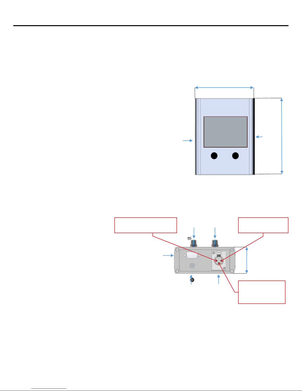
USB port
Quick Start Guide
4.2” (107mm)
Touch
Screen
I
I I
Marshall
ã
ç }
I
5.7” (145mm)
Serial
selector
switch
3. Dimensions
(W x H x D, excluding projections)
4.2” x 5.7” x 1.7” (1
07mm x 145mm x 43mm)
4. Inputs / Outputs
Remote: 3-pin XLR Female
AUX: D-sub 9 (future accessories)
USB: For firmware updates
DC Input : 2.1 mm coaxial power connector
5. Serial I/O
RS-485 Mode
Slide switch under cap on left side to RS-485 position
XLR pin 2 - RS-485A
XLR pin 3 - RS-485B
RS-232 Mode
Slide switch under cap on left side to RS-232 position
XLR pin 1 - Ground
XLR pin 2 - Tx
XLR pin 3 - Rx
Connect Pin
RS485 (phoenix) input (-) negative
#2 to CV camera
D-sub 9
Se ng adjustment knobs
I
I
. . . . .
. . . .
DC power
connector
I
Remote
connector to
camera
Pin#1 is Ground (not used
on RS485 installation)
1.7” (43mm)
Connect Pin
camera RS485 (phoenix)
input labeled (+) positive
#3 to CV
Marshall Electronics
Rev. 4 /0
9/22/2016
 Loading...