

Page 1
Broadcast A/V Division
CV50 6 - H12
Miniature High-Speed Camera
User Manual
Page 2
Table of Contents
Table of Contents
1. Menu Structure
2. OSD Joystick
3. WB Control
4. AE Control
5. Day / Night
6. Audio
7. Image Control
8. Special
9. Setup
10. Reset
01
02
02
05
06
07
08
09
10
11
12
11. E x it
12. Troubleshooting
Warranty
1
13
14
END
Page 3
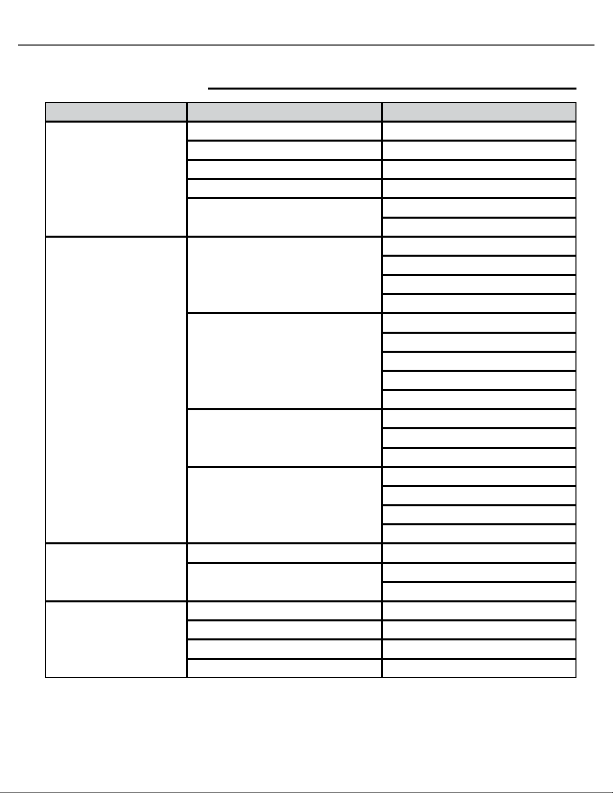
1. Menu Structure
CV506-H12 Manual
SETUP
WB CONTROL
AE CONTROL
SUB MENU
ATW
ONE PUSH
OUTDOOR
SUB MENU
MANUAL
AUTO
SHUT FIX
SUB MENU
BLUE
RED
AGC MAX
SENS UP
AE BRIGHT
FLK CONTROL
SHUTTER
FLK CONTROL
AGC MAX
SENS UP
AE BRIGHT
WB CONTROL
AUDIO
AGC FIX
MANUAL
DAY
NIGHT
AUDIO LEVEL
MIC/LINE
MIC AT TENUATOR
SAMPLE BITS
AGC
AE BRIGHT
FLK CONTROL
SHUTTER
AGC
SENS UP
FLK CONTROL
NIGHT COLOR
COLOR BURST
www.marshall-usa.com 2
Page 4
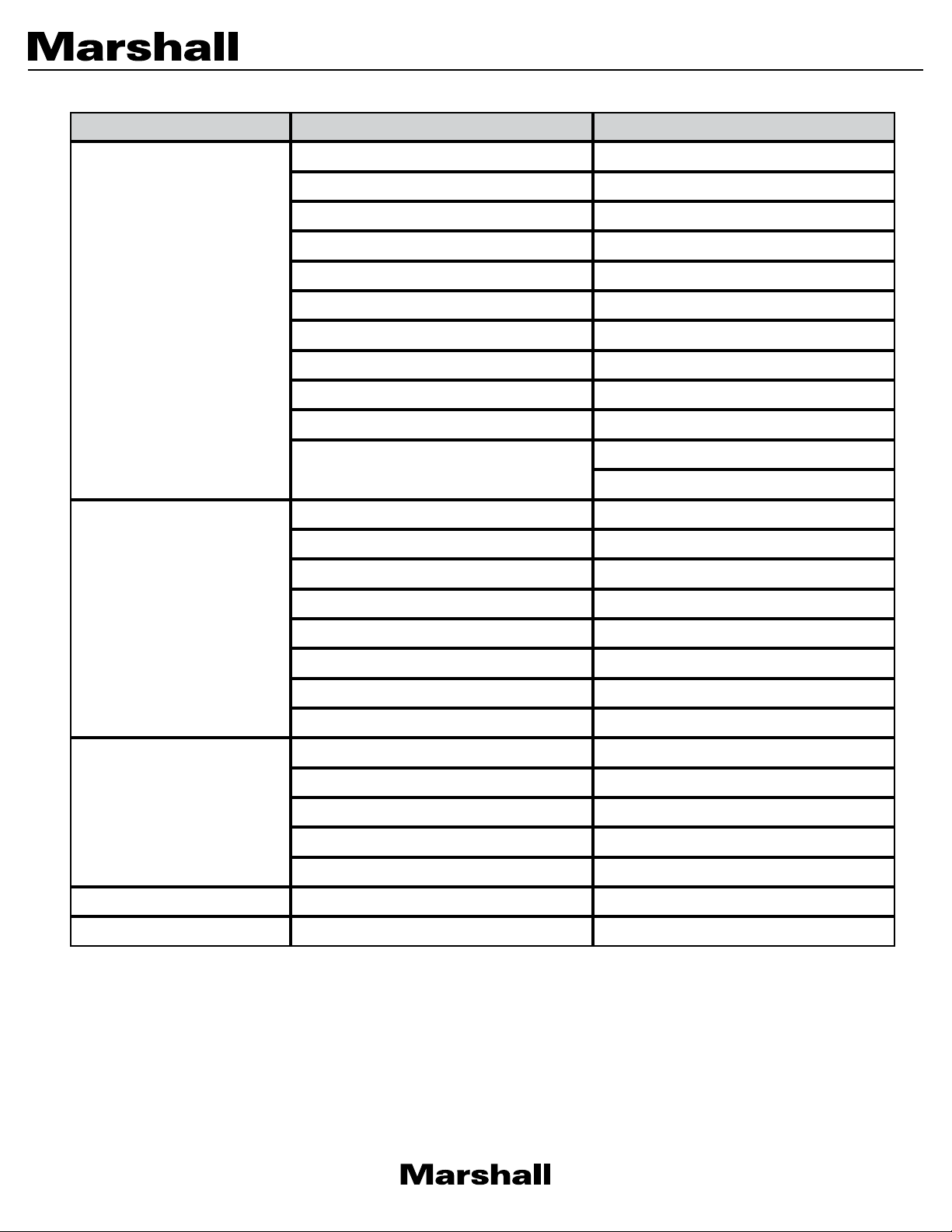
SETUP
SUB MENU
LENS SHADING
CONTRAST
BRIGHTNESS
SATURATION
HUE
SUB MENU
IMAGE CONTROL
PRIVACY
EDGE ENHANCE
AUTO SATURATE
AUTO EDGE
BLACK LEVEL
GAMMA CORRECT
DNR MODE
DNR
DNR LEVEL
DZOOM
DEFOG
BACKLIGHT
BINNING
DEFECT PIXEL
DISP FUNCTION
FLICKER DETECT
PRIVACY
CAM TITLE
RS-485/IDCOMMUNICATION
SETUP
RESET
EXIT
3
SYSTEM INFO
OUTPUT FORMAT
USER/FACTORY
Page 5
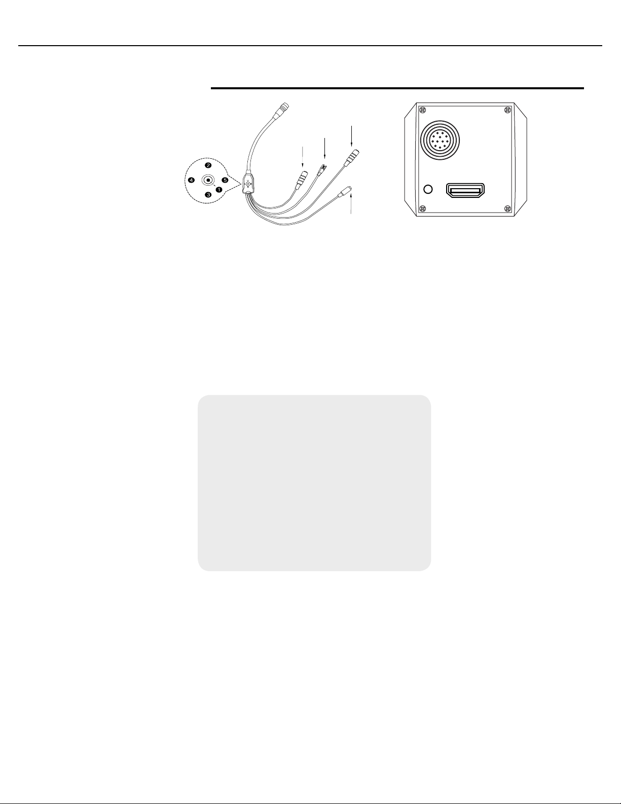
2. OSD Joystick
12G-SDI
I/O
IRIS
CV506-H12 Manual
1
2
3
4
5
SET
UP
DOWN
LEFT
RIGHT
Used to access the menu and confirm selection.
Used to move the cursor up.
Used to move the cursor down
Used to move the cursor to left and change the value.
Used to move the cursor to right and change the value.
Press SET button to access the MAIN MENU.
Use the UP & DOWN buttons to
select the desired item
.
MIC IN
RS485
LINE IN
U
R
L
D
POWER
I/O Cable for CV420-CS
I/O CABLE FOR CV506-H12 CV506-H12
I/O
POWER
1
SERVICE
2
I/O
HDMI
CV420-CS
MENU
WB CONTROL
AE CONTROL
DAY/N IGHT
AUDIO
IMAGE CONTROL
SPECIAL
SETUP
RESET
AUTO
>
AUTO>
>
>
OFF
>
ON>
Use the LEFT & RIGHT buttons
to change the sub-item
EXIT
12G-SDI
IRIS
.
Icon indicates “Press OSD Button” or “Enter Sub Menu”
>
www.marshall-usa.com 4
.
Page 6

3. WB CONTROL
Select WB CONTROL using the UP or DOWN button. You can change between AUTO, ATW, PUSH,
and MANUAL using the LEFT or RIGHT button.
• AUTO: Controls the automatic adjustment of the light source’s color temperature to 3,000°K ~
8,000°K.
• ATW : Continuously adjusts camera color balance in accordance with any change in color
temperature. Compensates for color temperature changes within the range of 1,900°K to
11,000°K.
• PUSH: Color temperature will be manually adjusted by pushing the OSD button. Place the
white paper in front of the camera when OSD button is pressed to obtain optimum result.
• MANUAL: Select this to fine-tune White Balance manually.
• You can adjust the blue and red tone level manually.
1. BLUE: Adjust the Blue tone of the image. (0~20)
2. RED: Adjust the Red tone of the image. (0~20)
• INDOOR: Select this to adjust white balance to indoor lighting condition.
• OUTDOOR: Select this to adjust white balance to outdoor lighting condition.
MENU WB CONTROL
WB CONTROL
AE CONTROL
DAY/N IGHT
AUDIO
IMAGE CONTROL
SPECIAL
SETUP
RESET
EXIT
1. Adjust White Balance first by using the AUTO or ATW mode before switching to MANUAL
mode.
2. White Balance may not work properly under the following conditions. In this case, select the
ATW mode.
• When the ambient illumination of the subject is dim.
• If the camera is directed towards a fluorescent light or installed in a place where
illumination changes dramatically, the White Balance operation may become unstable.
MANUAL
>
AUTO>
>
>
OFF
>
ON>
MODE
BLUE
RED
RETURN
PUSH
10
10
>
5
Page 7

CV506-H12 Manual
4. AE CONTROL
Select AE CONTROL using the UP or DOWN button. You can select one sub-mode using the UP or
DOWN button.
MENU AE CONTROL
WB CONTROL
AE CONTROL
DAY/N IGHT
AUDIO
IMAGE CONTROL
SPECIAL
SETUP
RESET
EXIT
MANUAL
>
AUTO
>
>
OFF
>
ON>
MODE
SHUT FIX
IRIS FIX
AGC FIX
RETURN
AUTO
>
• AUTO: Adjusts the exposure level automatically. Detailed fine tuning options are available
under this menu.
• SHUT FIX: Provides more detailed shutter speed options. All other controls are tuned for the
selected shutter speed.
• IRIS FIX: Provides more detailed iris control options. All other controls are tuned for the
selected iris setting.
• AGC FIX: Provides more detailed gain option. All other controls are tuned for the selected gain
value.
1. SHUTTER: Speed can be set at auto or manual. (1/30~1/10,000)
2. AGC MAX: Used to set maximum gain value to control the video noise caused by Auto
Gain Control. (Off, Low, Middle, High, DMIN, DMID, DMAX)
3. SENS UP: Controls the digital slow shutter to allow extra light into the camera and adjust
the picture quality. (Off, x2~x10)
4. AE BRIGHT: Select this to adjust auto exposure brightness levels. (0~10)
5. IRIS SPEED: Electronic Iris speed can be controlled, for DC Iris lens only. (0~5)
6. LENS MODE: Lens setting will be optimized for selected enviornment, for DC Iris lens only.
7. FLK CONTROL: Provides a proper image sensor frequency to match the power frequency
in order to minimize video flicker.
www.marshall-usa.com 6
Page 8

5. DAY / NIGHT
Select DAY / NIGHT using the UP or DOWN button. You can select one sub-mode from AUTO,
COLOR, and NIGHT using the UP or DOWN button.
MODE: Set camera to either color mode or B&W mode. (Day, Night)
DAY: When set to DAY mode, camera stays in color and IR cut filter is engaged.
NIGHT: When set to NIGHT mode, camera stays in B/W and IR cut filter is removed.
• NIGHT COLOR: When on, camera stays on color mode. Night (B&W) can be selected from
this mode. (On, Off)
• COLOR BURST: Signal ON or OFF can be set for CVBS signal. (On, Off)
MENU DAY/NIG HT
WB CONTROL
AE CONTROL
DAY/N IGHT
AUDIO
IMAGE CONTROL
SPECIAL
SETUP
RESET
EXIT
MANUAL
>
AUTO>
>
>
OFF
>
ON>
MODE
NIGHT COLOR
COLOR BURST
RETURN
DAY (COLOR)
>
7
Page 9

CV506-H12 Manual
6. AUDIO
Select AUDIO using the UP or DOWN button and enter ON using SEL button. You can select one
sub-mode using the UP or DOWN button.
• MIC / LINE: When using audio microphone use MIC mode, when using other audio sources
use LINE setting.
• AUDIO LEVEL: Select this to adjust audio levels, manually.
• MIC AT TENUATOR : Audio attenuation can be controlled from this menu to minimize the
audio noise level.
1. SAMPLE BITS: Select the bit depth of audio.
MENU AUDIO
WB CONTROL
AE CONTROL
DAY/N IGHT
AUDIO
IMAGE CONTROL
SPECIAL
SETUP
RESET
EXIT
MANUAL
>
AUTO>
>
>
OFF
>
ON>
MIC LINE
AUDIO LEVEL
MIC AT TENUATOR
SAMPLE BITS
RETURN
24
24 BITS
>
www.marshall-usa.com 8
Page 10

7. IMAGE CONTROL
Select IMAGE CONTROL using the UP or DOWN button.
You can select LENS SHADING, CONTRAST, HUE, And EDGE ENHANCE using the UP or DOWN
button.
MENU IMAGE CONTROL
WB CONTROL
AE CONTROL
DAY/N IGHT
AUDIO
IMAGE CONTROL
SPECIAL
SETUP
RESET
EXIT
MANUAL
>
AUTO
>
>
OFF
>
ON>
LENS SHADING
CONTRAST
BRIGHTNESS
SATURATION
HUE
EDGE ENHANCE
AU TO SATUR ATE
BLACK LEVEL
GAMMA CORRECT
DNR
RETURN
OFF
10
10
10
0
5
MIDDLE
0
DEFAULT
>
• LENS SHADING: Corrects inconsistent brightness level in the image.
• CONTRAST: Adjust the image contrast level value.
• BRIGHTNESS: Adjust the image brightness level value.
• SATUR AT ION : Adjust the image saturation level value.
• HUE: Adjust the image hue level value.
• EDGE ENHANCE: Adjust the image sharpness level.
• AU TO S ATURAT E : Decrease saturation automatically when noise scene is detected.
• BLACK LEVEL: Adjust the image black level value.
• GAMMA CORRECT: Adjust the image output gamma level.
• DNR: Reduces video noise at low ambient light.
Select the DNR level from OFF, LOW, MIDDLE, and HIGH using the LEFT or RIGHT button.
9
Page 11

CV506-H12 Manual
8. SPECIAL
Select SPECIAL using the UP or DOWN button.
You can select DEFOG, MOTION DETECT, BACKLIGHT, DEFECT PIXEL, and FLICKER DETECT using
the UP or DOWN button.
MENU SPECIAL
WB CONTROL
AE CONTROL
DAY/N IGHT
AUDIO
IMAGE CONTROL
SPECIAL
SETUP
RESET
EXIT
MANUAL
>
AUTO
>
>
OFF
>
ON>
DZOOM
DEFOG
DWDR
DIS
BACKLIGHT
BINNING
DEFECT PIXEL
DISP FUNCTION
FLICKER DEFECT
PRIVACY
RETURN
ON
OFF
OFF
OFF
OFF
OFF
ON>
>
ON>
>
>
• DZOOM: Digitally zoom the video by the desired ratio.
• DEFOG: This feature will help increase visibility in extreme weather conditions such as fog,
rain or any other luminous setting.
• DWDR: This feature enables the user to view both the object and the background more clearly
when background is too bright.
• DIS: This feature enables digital image stabilization to prevent the image from being shaken.
• BLACKLIGHT: Adjust blacklight compensation by choosing either BLC or HLM from this
menu.
• BINNING: Enable or disable pixel binning.
• DEFECT PIXEL: Advanced defective pixel correction menu.
• DISP FUNCTION: Display effects such as freeze mirror, rotation, and style can be applied
from this menu.
• FLICKER DETECT: Adjust the image sensor frequency to match the power frequency.
• PRIVACY: Mask an area you want to hide on the screen by applying the privacy zones.
www.marshall-usa.com 10
Page 12

9. SETUP
CAMERA setup can be adjusted from this menu.
You can select CAMERA ID, Communication, System Info, and Output Format using the UP or DOWN
button.
MENU SETUP
WB CONTROL
AE CONTROL
DAY/N IGHT
AUDIO
IMAGE CONTROL
SPECIAL
SETUP
RESET
EXIT
MANUAL
>
AUTO
>
>
OFF
>
ON>
CAM TITLE
COMMUNICATION
SYSTEM INFO
OUTPUT FORMAT
RETURN
ON
>
>
1080p 59.94
>
• CAM TITLE: Camera title can be turned ON or OFF.
• COMMUNICATION: VISCA communication can be adjusted.
1. CAM ID: Camera ID can be setup. (0~7)
2. ID DISPLAY: Camera ID display can be displayed.
3. BAUDR ATE : Camera baudrate can be set.
(2400, 4800, 9600, 19200, 38400)
• SYSTEM INFO: Camera information can be found under this menu.
• OUTPUT FORMAT: Camera resolution and frame rate can be set.
(1080 by default)
Select the FRAME RATE using the LEFT or RIGHT button. Available Frame Rates are:
1920 x 1080p 120, 100, 60, 59.94, 50, 30, 29.97, 25, 24, 23.98
1920 x 1080i 60, 59.94, 50
1280 x 720p 120, 100, 60, 59.94, 50
11
Page 13

CV506-H12 Manual
10. RESET
Select RESET using the UP or DOWN button.
• RESET: Reset the camera settings the factory defaults or user setting value
MENU RESET
WB CONTROL
AE CONTROL
DAY/N IGHT
AUDIO
IMAGE CONTROL
SPECIAL
SETUP
RESET
EXIT
MANUAL
>
AUTO>
>
>
OFF
>
ON>
RESET MODE
RESET
SAVE AS USER
RETURN
FACTORY
>
• ON: Set the camera setting to either “FACTORY” or “USER” of “CHANGE” menu. Make sure
to select the right mode from “CHANGE” before defaulting the camera.
• RESET MODE: Select the desired setting mode.
Select from USER or FACTORY using the LEFT or RIGHT button.
1. USER: Select “USER” if setting value user saved last is needed.
2. FACTORY: Select “FACTORY” if factory default setting is needed.
“FRAME RATE”, “CAM ID”, and “BAUDRATE” will note change.
www.marshall-usa.com 12
Page 14

11. EX IT
Select EXIT using the UP or DOWN button.
MENU
WB CONTROL
AE CONTROL
DAY/N IGHT
AUDIO
IMAGE CONTROL
SPECIAL
SETUP
RESET
EXIT
• SAVE : Exit the setup after saving the value changes.
MANUAL
>
AUTO
>
>
OFF
>
ON>
13
Page 15

12. TROUBLESHOOTING
Before sending the camera for repair, please check below to make sure that the camera is
installed correctly. If it still does not perform adequately, please consult with your supplier.
Problem Solutions
a. Check that all connected devices are powered on.
Nothing appears
on the screen.
The picture is
not clear.
b. Confirm that the voltage is correct.
c. Confirm that the power supply provides enough current to power the camera.
d. Check that all video cables are correctly connected.
a. Check that your monitor is correctly adjusted.
b. Confirm that the glass in front of the lens is clean. If there is dust, dirt, or
fingerprints on the glass, the image quality will be affected.
To clean the glass, use a soft, dry, and non-abrasive cloth or a commercially
available lens cleaning set.
c. Correctly adjust the focus.
CV506-H12 Manual
The picture has
interference.
The picture is
flickering
continually.
The camera is not
synchronizing with
the reference signal.
a. The camera may be close to a high voltage source, such as a power generator.
b. The BNC cable is not terminated properly.
c. The video cables are not connected properly.
a. Check the termination and set the impedance at 75 properly.
b. Ensure that the camera is not pointing towards the Sun or any light source.
c. Check if there is any intermediate device.
d. Check if the distance of the video cable exceeds the maximum transferable
limitation.
a. Make sure Tri-Level reference signal is used.
b. Locking takes up to 1 minute depending on the signal strength.
Make sure the sync LED is solidly lit.
c. Check if the cable and connectors used in reference sync are in good condition.
d. Make sure the cable length used in reference sync does not exceed 100 ft.
e. Make sure OUTPUT EN is on when using the genlock output.
www.marshall-usa.com 14
Page 16

Warranty
Marshall Electronics warranties to the first consumer that this device will, under normal use,
be free from defects in workmanship and materials, when received in its original container, for
a period of two years from the purchase date. This warranty is extended to the first consumer
only, and proof of purchase is necessary to honor the warranty. If there is no proof of purchase
provided with a warranty claim, Marshall Electronics reserves the right not to honor the warranty
set forth above. Therefore, labor and parts may be charged to the consumer. This warranty
does not apply to the product exterior or cosmetics. Misuse, abnormal handling, alterations or
modifications in design or construction void this warranty. No sales personnel of the seller or
any other person is authorized to make any warranties other than those described above, or to
extend the duration of any warranties on behalf of Marshall Electronics, beyond the time period
described above.
Due to constant effort to improve products and product features, specifications may change
without notice.
20608 Madrona Avenue, Torrance, CA 90503
Tel: (800) 800-6608 / (310) 333-0606 • Fax: 310-333-0688
www.marshall-usa.com
support@marshall-usa.com
JR12 2717
 Loading...