

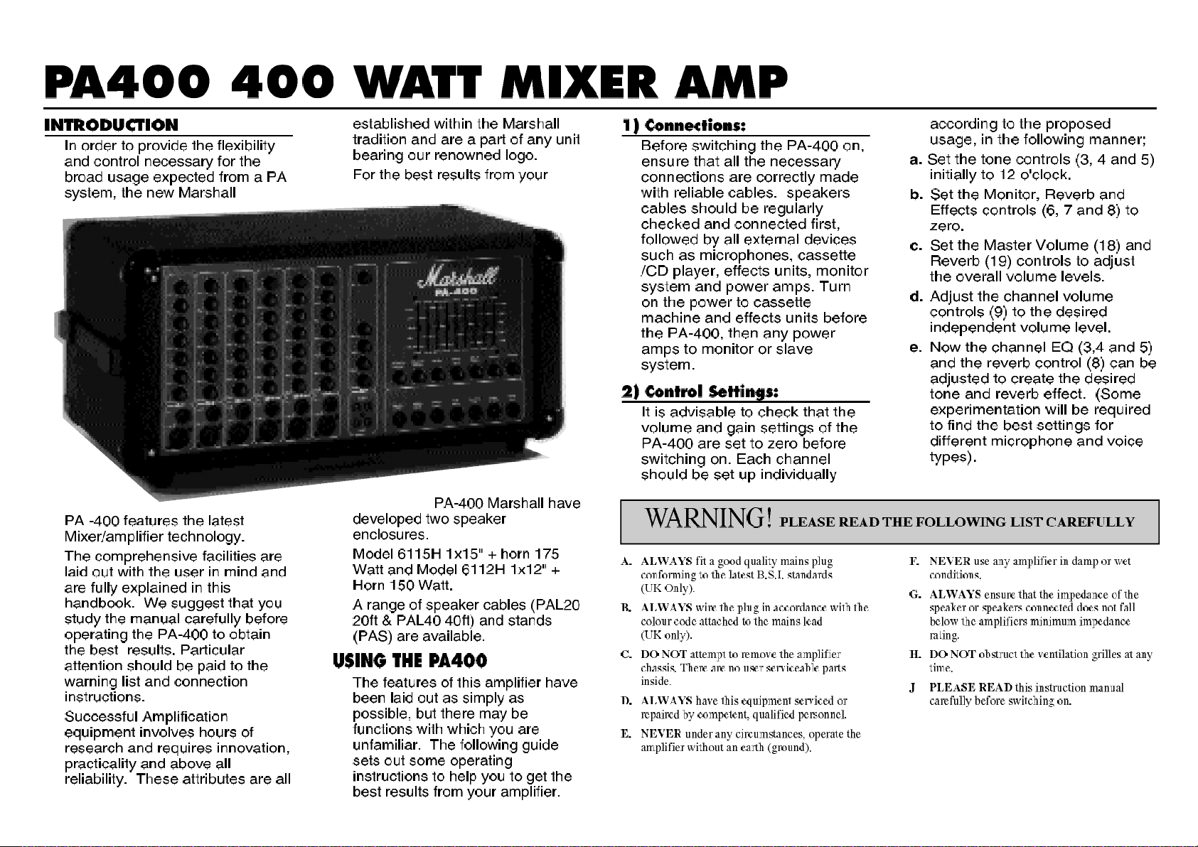
Page 1
Page 2
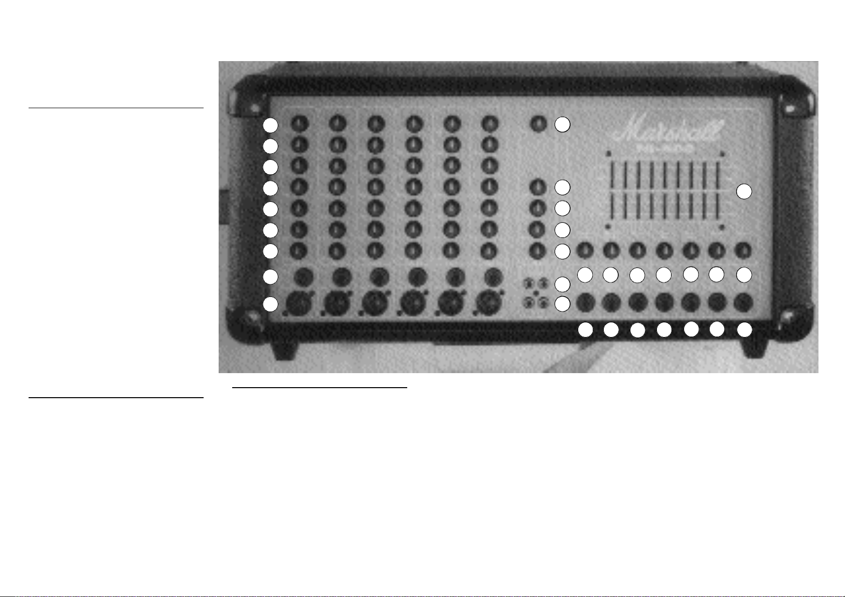
PA400 FRONT PANEL
PA400 Front Panel
Functions.
Channels 1-6
1. Low impedance XLR input - For the
connection of low impedance
microphones.
2. High impedance Jack input - For the
connection of high impedance
microphones. Also suitable for acoustic
instruments with transducer type
pick-ups.
3-5. Bass, Middle and Treble EQ controls-
A wide range of tonal adjustment can be
selected using combinations of these
controls.
6. Monitor level - Provides the volume level
adjustment from the channel to the
monitor section.
7. Effects Level - Provides level adjustment
of the signal from the channel to effects
units linked through the master effects
loop.
8. Reverb Level - Allows the level of the
built in reverb to be adjusted on the
channel.
9. Volume control - This allows the
individual volume level of the channel to
be adjusted.
Channel 7 (tape channel).
10. Tape inputs - Phono (RCA) sockets to
accept the signal from tape or CD
players.
11. Tape outputs - Phono (RCA) sockets to
provide connection out to cassette or
other recording equipment.
12. Recording level control - Provides level
control of the output to external recording
equipment.
13- 14. Bass and Treble EQ controls - A
wide range of tonal adjustment can be
selected using combinations of these
controls.
15. Monitor control - Controls the level of
the tape signal to the monitor output.
16. Volume control - Provides level control
of the tape channel output.
Master Section.
17. 9 Band Graphic Equalizer - Provides
master EQ control across the audio
spectrum. This feature is particularly
useful for "shaping" the sound to achieve
peak performance in rooms of different
size and texture. Adjustment of -12 to
+12 dB is provided at 63Hz, 125Hz, 250
Hz, 500 Hz, 1 K Hz, 2 K Hz, 4 K Hz, 8 K
Hz and 16 K Hz. The slider tips are
loaded with an LED to provide the
display of graphic "shapes", even on
darkened stages.
18. Master Volume control - Controls the
overall volume level of the amplifier.
19. Master Reverb control - Provides the
overall level control of the reverb.
20. Effects Return control - Controls the
level of the signal returning to the
PA-400 from external effects processors
which would be linked through effects
loop sockets (26 & 27).
21. Effects Send control - Controls the level
of the signal from the PA-400 to the input
of external effects processors.
22.
Monitor output control - Controls the
level of the output from monitor socket
(25) to drive a separate monitor power amp.
23. Effects to Monitor control - Provides
level adjustment of the effects return into
the monitor mix.
24. Reverb to Monitor control - Provides
level adjustment of the reverb into the
monitor mix.
25. Monitor output - Jack socket for
connection to power amplifier driving the
monitor system.
26. Effects Send - Jack socket for connection
to the input of external effects processors.
27. Effects Return - Jack socket which
accepts the signal from the output of
external effects processors.
28.
Footswitch socket - For connection of a
two way (FS02) switch for reverb on/off
and effects loop in/out. If a single
footswitch is used, the reverb only will be
switched.
29. Pre-amp output - Provides a signal
directly out from the pre-amp (also mutes
the power amp) allows external
processing of signal which can then be
returned to Power Amp in socket (30).
30. Power Amp input - Provides a direct
input to the power amp stage of the
PA-400. Also acts as the effects return for
series connected processors linked via
socket (29).
31. Slave output - Sends out an overall
signal from the mixer section, suitable for
driving extra power amps, if the system
needs to be extended.
8
9
1
2
3
4
5
6
7
16
15
17
18
1920
21
22
2324
14
13
12
11
10
25 26
27
28
29 30
31
Page 3

PA400 REAR PANEL
of the tape channel output.
PA-400 from external effects processors
to the input of external effects processors.
27. Effects Return - Jack socket which
driving extra power amps, if the system
needs to be extended.
Rear Panel Features.
32. Mains switch - Mains on/off switch
33. Mains Input- Socket to accept the mains
power lead supplied. (note: please ensure
that correct wiring practices have been
observed before use).
34-35. Loudspeaker outputs - Jack sockets
for the connection of loudspeaker
systems. The power output is 400 Watts
into 2 Ohms. Under no circumstances
should a total loudspeaker load of less
than 2 Ohms be connected.
SPECIFICATIONS
Channels 1-6
Low impedance 3 pin XLR balanced input.
Sensitivity -50dBm.
Input impedance 10K
Ω.
High impedance 2 pole jack unbalanced
input.
Sensitivity -30dBm.
Input impedance 1 M
Ω.
Bass control +/- 12dB @ 100 Hz.
Middle control +/- 12dB @ 600 Hz.
Treble control +/- 12dB @ 10KHz.
Channel 7 (tape channel).
Input impedance 33K
Ω.
Input sensitivity -20dBm.
Bass control +/- 12dB @ 100Hz.
Treble control +/- 12dB @ 10 KHz.
Output level 0 dBm.
Output impedance 500 Ω.
Master section
Graphic equalizer 9 band giving +/- 12dB @
centre frequencies of
63Hz, 125Hz, 250Hz.
500Hz, 1KHz, 2KHz,
4KHz, 8KHz and16KHz.
Effects output level 0dBm nominal.
Effects output impedance 500 Ω.
Effects input sensitivity impedance -10dBm.
Effects input impedance 10K
Ω.
Monitor output level 0dBm nominal.
Monitor output impedance 500 Ω.
Pre-amp/slave output level 0dBm nominal.
Pre-amp/slave output 500 Ω.
Power Amplifier
MOSFET power output stage 400 Watts into 2
Ω.
300 Watts into 4
Ω.
200 Watts into 8
Ω.
Output offset voltage +/- 10mV.
Frequency response +/- 0.5dB 10Hz -20KHz.
Hum and noise Greater than -100dB.
Load impedance 2 Ωor greater.
Output protection Open circuit, short circuit,
load mismatch and over
temperature protection.
Input sensitivity 0dBm for 400W into 2 Ω.
Input impedance 47K Ω.
Slew rate 50V /µS.
The PA-5400 has a built in cooling fan to ensure reliable operation
under the most arduous conditions. The fan will switch on when
the internal temperature exceeds 60°C and will automatically turn
off again when the temperature drops below 55°C.
32
33
34
 Loading...