

Page 1
Broadcast A/V Division
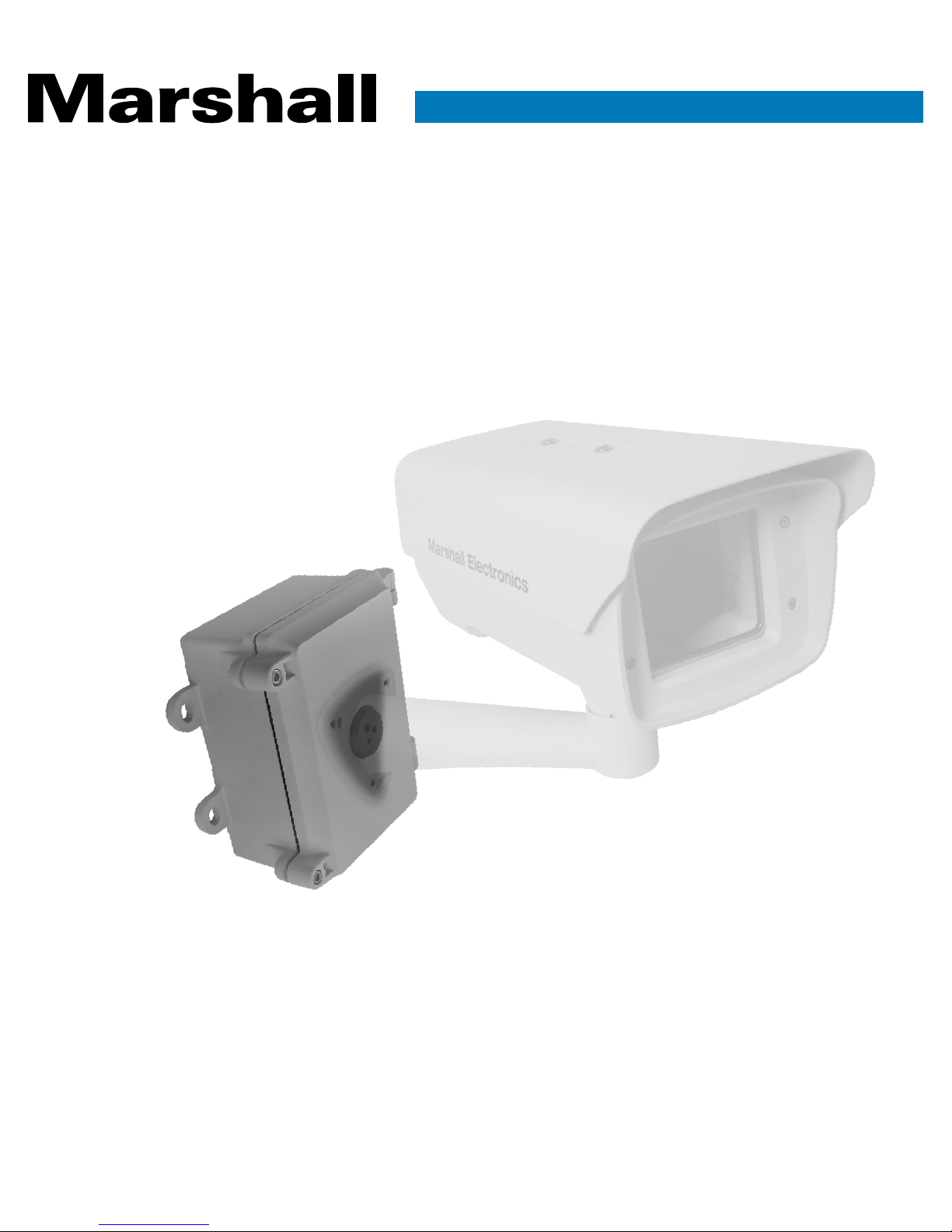
CV-H20-PWR
Power Supply & Enclosure
User Manual
Page 2

Table of Contents
1. Warning .............................................................................................................. 2
2. AC 24V Power Box ............................................................................................. 3
3. Installation of AC 24V Adapter ........................................................................... 4
PCB CV-H20-PWR ................................................................................................ 4
PCB CV-H20-HF ................................................................................................... 4
Power Cord Installation .......................................................................................... 5
Power Cable L605P-2 (no terminal) Installation ........................................................... 7
220~240 VAC Power input Connection ......................................................................7
110~120 VAC Power input Connection ...................................................................... 4
4. Dimensions ........................................................................................................ 8
5. Important Safeguards ...................................................................................... 10
6. Safety Precautions .......................................................................................... 10
7. Unpacking ........................................................................................................ 10
1
Page 3
1. Warning
WARNING
To reduce the risks of an electric shock, do not expose inside of this unit to rain or
moisture.
Installation on a rainy day may also cause fog around the capsule.
Installation
Installation shall be done by qualified installer only and should conform to all local codes.
Ensuring strength of supporting Housing Unit
The unit must be properly and securely mounted to a supporting structure capable of
sustaining the weight of the unit. Recommend using 3/8” stainless screws x four (4).
Prohibit changes or modifications of equipment
You are cautioned that any changes or modifications not expressly approved in these
instructions could void your authority to operate this equipment.
CV-H20-PWR Manual
Basic Operating Environment Condition
We provide warranty for the products that are installed under normal outdoor -20°C
~ +50°C conditions. We are unable to provide warranty for the products which are
installed indoors and exposed to constant high temperature over +50°C and over 90%
humidity.
Operating temperature and humidity of camera varies from camera to camera. You are
requested to conform to camera specifications with camera manufacturer and housing
specifications in advance.
i.e. -20°C or below, you are requested to use additional heater and +50°C or above you
are requested to use two blowers and Sunshield.
Fasten wires tightly.
Attention:
Keep wires away from the Fan / Heater, and do not disturb Fan/Heater’s performance
www.marshall-usa.com 2
Page 4
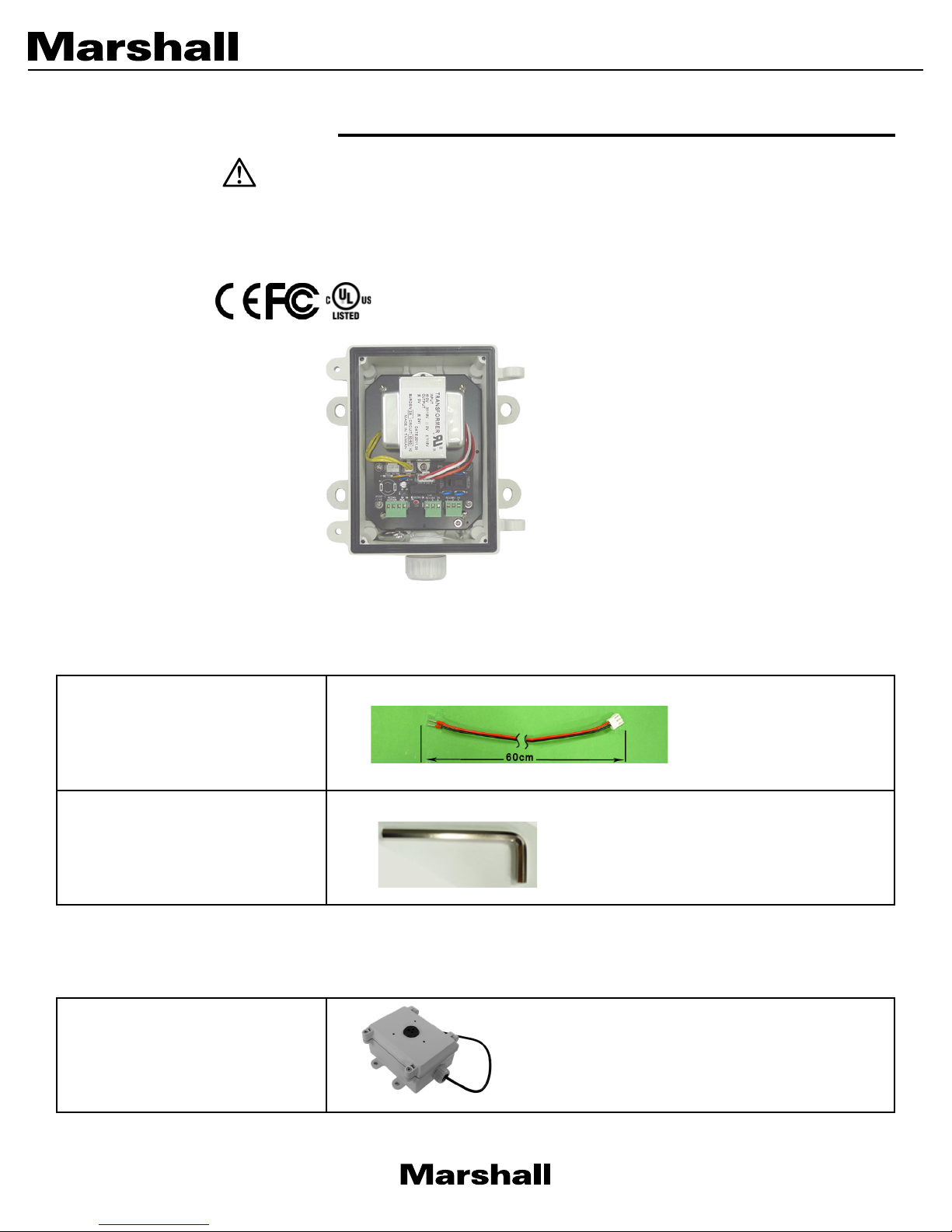
2. AC 24V Power Box
WARNING
The unit must be properly and securely mounted to a supporting structure capable of sustaining the
weight of unit. Recommend using stainless screws.
Compliance To (Only for Transformer)
Accessories
L605P-2:
Power Output Cable from CVH20-PWR circuit board to fan/
heater board in housing
No. 5 Allen Key:
To screw the 6 x 20 hex head
cap
Application Product
Wall Mount Bracket
3
Page 5

3. Installation of AC 24V Adapter
FUSE 5X20
AC230V IN
L1 L2 G
AC115V IN
L N G
AUX
AC24V
HEATER
LED
PS-2430.0
AC115V
AC230V
AC24V OUT GND
115V 0 115V 0
4
1
2
3
5
5
1
2
3
4
Figure A: PCB CV-H20-PWR
1. AC24V OUTPUT
CV-H20-PWR Manual
2. AC24V output for heater and AUX
3. AC110~120V INPUT
4. 115/230VAC Switch
5. AC220~240V INPUT
Figure B: PCB CV-H20-HF
1. AC24V OUTPUT
2. DC12V OUTPUT
3. DC12V FAN
4. AC24V INPUT
5. AC24V HE ATER
www.marshall-usa.com 4
Page 6

FUSE 5X20
AC230V IN
L1 L2 G
AC115V IN
L N G
AUX
AC24V
HEATER
LED
PS-2430.0
AC115V
AC230V
AC24V OUT GND
115V 0 115V 0
~~
G
Power cord installation:
1. Make the power cord go through the cable gland into the power box, and use the cable strap
to fix it on the box’s plate.
2. Fix 3 wires with Phoenix connector, the green wire needs to be fixed into G (Ground) position.
3. After fixing ready wires of power cord on Phoenix connector, plug the Phoenix connector
into CV-H20-PWR PCB AC115V or AC230V connector (depends on your power input).
Power Cable L605P-2 (no terminal) installation:
1. Go
2. Another side of cable, goes through the box housing’s cable gland to fix on terminal
through Cable L605P-2 (no terminal) into the cable gland and plug on AC24V out
connector. (Please refer to figure A, No. 1).
as below image. (Please refer to figure B, No. 4).
5
Page 7

CV-H20-PWR Manual
WARNING
For safety purposes, all following installations of electrical cables should be done by a
qualified, trained electrician, or technician.
DANGER!
For preventing electric shock, before all cables are wired properly DO NOT plug AC powerplugs into 3 pin sockets.
DANGER!
Please make sure AC power-plugs DO NOT PLUG into 3 pin sockets before step 4-1 or 4-2.
www.marshall-usa.com 6
Page 8

For 220~240VAC Power input Connection
4-1
For 220~240VAC Power input connection, connect L(Live), N(Neutral), and G(Ground) power wires
to corresponding screw terminal of AC230V POWER INPUT (part 5), and turn switch (part no. 4) to
AC 230V.
For 110~120 VAC Power input Connection
4-3
For 110~120VAC VAC Power input connection, connect L(Live), N(Neutral), and G(Ground) power
wires to corresponding screw terminal of AC115V POWER INPUT (part no. 3), and turn switch (part
no.4) to AC115V.
7
Page 9

CV-H20-PWR Manual
42
21
60
89
72.6
100.5 97
264
72
67
Note:
For one heater, total power is 3A (around 72W), fan and heater consume around 25W.
After fan and heater working, there is 47W power that can be used.
Recommend using two heaters at the area which is below -25 C. For two heaters, total power is 3A
(around 72W), fan and heater consume around 45W.
After fan and heater working, there is 27W power that can be used.
4. Dimensions
Wall mount bracket
www.marshall-usa.com 8
Page 10

Power box
9
Page 11

CV-H20-PWR Manual
IMPORTANT SAFEGUARDS
1. Read Instructions – All the safety and operating instructions should be read before operating the unit.
2. Retain Instructions – The safety and operating instructions should be retained for future reference.
3. Heed Warnings – All warnings on the unit and in the operating instructions should be adhered to.
4. Follow Instructions – All operating user instructions should be followed.
5. Electrical Connections – Only a qualified electrician should make the electrical connections.
6. Attachments – Do not use attachments not recommended by the product manufacturer as they may cause
hazards.
7. Cable Runs – All cable runs must be within permissible distance.
8. Mounting – This unit must be properly and securely mounted to a supporting structure capable of sustaining
a. The installation should be made by a qualified installer.
b. The installation should be in compliance with local codes.
c. Care should be exercised to select suitable hardware to install the unit, taking into account both the
composition of the mounting surface and the weight of the unit. Be sure to periodically examine the unit and
the supporting structure to make sure that the integrity of the installation is intact. Failure to comply with the
foregoing could result in the unit separating from the support structure and falling, with resultant damages
or injury to anyone or anything struck by the falling unit.
SAFETY PRECAUTIONS
CAUTION
RISK OF
ELECTRIC SHOCK!
CAUTION: TO REDUCE THE RISK OF
ELECTRICAL SHOCK, DO NOT EXPOSE
COMPONENTS TO WATER OR MOISTURE.
The lightning flash with an arrowhead symbol, within an equilateral triangle, is intended to alert the user to
the presence of non-insulated “dangerous voltage” within the product’s enclosure that may be of sufficient
magnitude to constitute a risk of electric shock to persons.
The exclamation point within an equilateral triangle is intended to alert the user to the presence of
important operating and maintenance (servicing) instructions in the literature accompanying the appliance.
UNPACKING
Unpack carefully. Electric components can be damaged if improperly handled or dropped. If any of the products
appear to have been damaged during the shipment, replace it properly in its carton and notify the shipper.
Be sure to save:
1. The shipping carton and packaging material. They are the safest material in which to make future shipments of
the equipment
2. The Installation and Operating Instructions.
www.marshall-usa.com 10
 Loading...