

Page 1
CV620-IP / CV620-IPW
Full HD PTZ Conference IP Camera
User Manual
Page 2

CV620-IP / CV620-IPW
2 User Manual v.1
Table of Contents
Chapter 1. Safety Instructions ........................................................................................ 3
Chapter 2. Package Contents ......................................................................................... 5
Chapter 3. Product Overview .......................................................................................... 6
3.1 Overview ........................................................................................................................................ 6
3.2 Descriptio n of LED indicat or .......................................................................................................... 6
Chapter 4. Instruction f or installation ............................................................................ 7
4.1 Preparatio n b efore instal l at i on ....................................................................................................... 7
4.2 Instruction for installation ............................................................................................................... 7
4.3 Connecting devices ..................................................................................................................... 14
Chapter 5. Remote Control and Setting Menu ............................................................ 18
5.1 Functions of remote control ......................................................................................................... 18
5.2 Setting Menu ................................................................................................................................ 19
Chapter 6. Descriptions of Major Function s ............................................................... 25
6.1 I would like to switch to CV620-IPW............................................................................................ 25
6.2 I would like to save the current lens position data ...................................................................... 25
6.3 I would like to clear the saved position data ............................................................................... 25
6.4 I would like to turn on the back light compensation function ...................................................... 25
6.5 I would like to adjust the shooting angle of the lens ................................................................... 25
6.6 I would like to zoom in/out images .............................................................................................. 25
6.7 I would like to adjust the focal length .......................................................................................... 25
6.8 I would like to adjust the AF speed .............................................................................................. 25
6.9 I would like to s et the image mode .............................................................................................. 26
6.10 I would like to freeze images ....................................................................................................... 26
6.11 I wo u ld l ike to rotate the image .................................................................................................... 26
6.12 I would like to change the camera direction ................................................................................ 26
6.13 I would like to display the current status ..................................................................................... 26
6.14 I would like to r ese t t o th e default value ...................................................................................... 26
Chapter 7. Network Function Settings Description .................................................... 27
7.1 Web System Requirements ......................................................................................................... 27
7.2 Online IP Camera ........................................................................................................................ 27
7.3 Web Page Function Description .................................................................................................. 29
Chapter 8. DIP switch setting ....................................................................................... 36
8.1 DIP SWIT C H ................................................................................................................................ 36
8.2 RS-422 Connection ..................................................................................................................... 37
Chapter 9. Troubleshooting .......................................................................................... 39
Page 3

CV620-IP / CV620-IPW
3 User Manual v.1
Chapter 1. Safety Instructions
Please use t he pro duct follow ing the safet y ins tr uctions below:
1 Operation
1.1 Pleas e use the produc t in the r ec ommended operating env iro nment.
1.2 Do not place Light Engine in tilted position.
1.3 Do not place the product on an unstable trolley, stand or table.
1.4 Do not use this product near water or source of heat.
1.5 Use attachments only as recommended.
1.6 Use the type of power source indicated on the HD Camera. If you are not sure of the type of power
available, consult your dealer or local electricity company for advice.
1.7 Always take the following precautions when handling the plug. Failure to do so may result in sparks or fire.
Ensure the plug is free of dust before inserting it into a socket.
Ensure that the plug is inserted into the socket securely.
1.8 Do not overload wall sockets, extension cords or multi-way plug boards to avoid potential risks.
1.9 Do not block slots and openings in the case of this product as poor ventilation may lead to overheating of
this product.
1.10 Except as spec if ically instr uc t e d i n th is User Manua l , do no t a ttempt to open or remove cov er s by yourself.
It may expose you to electric shock or other hazards. Refer all servicing to licensed service personnel.
1.11 Unplug this product from the wall outlet and refer servicing to licensed service personnel when the
following situations happen:
If the power cords are dam ag e d or frayed.
If liquid is s p i l le d in t o th e H D Camera or the HD C amera has been ex p os e d to r a i n or w at e r.
2 Installation
2.1 For security consi d erations, ple ase make sure th e s t a nd ard hanging r ac k you b o ught is in line wi t h U L or
CE safety approbation s and installed by technician personnel approved by agents.
3 Storage
3.1 Do not p lac e the HD Camera wh er e the cord can be st ep p e d on as th is may result i n fraying or dam ag e t o
the lead or the plug.
3.2 Never push objects of any kind through cabinet slots. Never allow liquid of any kind to spill into the HD
Camera.
3.3 Unplug this product during thunderstorms or if it is not going to be used for an extended period.
3.4 Do not p lac e this product o r accessories on to p of v i br at i ng equipment or heated objects.
4 Cleaning
4.1 Unplug all the cables before cleaning. Use a damp cloth for cleaning. Do not use liquid or aerosol
cleaners.
5 Remote control (if the accessories are equipp ed with remote control)
5.1 Usin g a n i ncorrect batt ery type in the remote contro l may result in bre akdown. Fol low local instructions on
how to dispos e of used batteri es .
Precautions
Warning: To reduce the risk of fire or electric shock, do not expose this appliance to rain or moisture.
If HD Camera will not be used for an extended time, unplug it from the power socket.
Page 4

CV620-IP / CV620-IPW
4 User Manual v.1
Caution: To reduce the risk of electric shock, do not remove cover (or back). No user-
serviceable parts inside. Refer servicing to licensed service personnel.
This symbol indicates that
this equipment may contain
dangerous voltage which
could cause electric shock.
This symbol indicates that
there are im por t ant
operating and maintenance
instructio ns i n t his U ser
Manual with this unit.
FCC Warning
This HD Camera has been tes te d an d f ound to comply with the lim its for a Cl as s A digital device, pursuant to
Article 15-J of FCC Rules. These l imits are desig n e d t o provide reas o na ble protecti o n a ga i nst harmful i nt erference
in a commer cia l i nstallation.
This digital apparatus does not exceed the Class A limits for radio noise emissions from digital appar at us as set
out in the inter f erence-causing equipment standard entitled "Digi ta l Apparatus," ICES-003 of Industry Canada.
Cet appare il n umerique res pecte les lim it es d e bruits radio electriques applicables aux apparei ls n umeriques de
Classe A prescrites dans la norme sur le material brouilleur: "Appareils Numeriques," NMB-003 edictee par
l'Industrie.
EN55032 (CE Radiation) Warning
Operation of this equipment in a residential environment could cause radio interference.
Note
Risk of Electric Shock
Please do not open it by yourself.
Page 5
CV620-IP / CV620-IPW
5 User Manual v.1
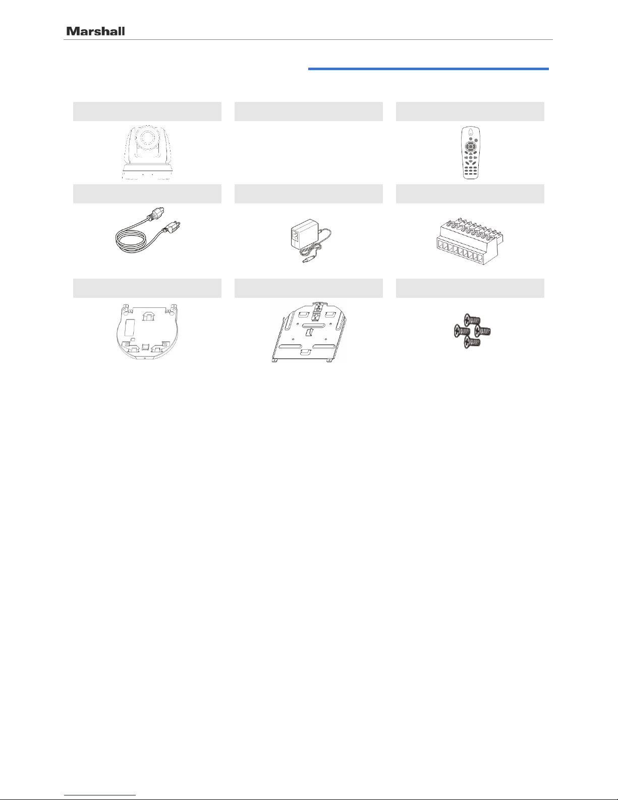
Chapter 2. Package Contents
CV620-IPW Instruction for installation Remote Control
Power Cord Power Adapter RS-422 Connector
Appearance may vary depending
on country/region
Metal Plate A Metal Plate B M3 Screws
Page 6
CV620-IP / CV620-IPW
6 User Manual v.1
Chapter 3. Product Overview
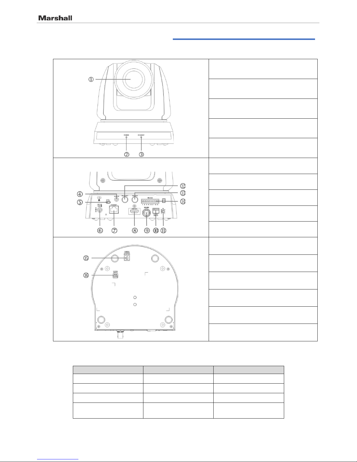
3.1 Overview
1. Camera lens
2. Power LED indicator
3. Standby LED indicator
4. Audio In
5. USB port (for FW update)
6. Power input
7. Network port (supported for PoE)
8. HDMI Output
9. 3G-SDI
10. OUTPUT Switch
11. IR SELECT
12. RS-232 output
13. RS-232 input
14. RS-422 Connection
15. Camera Address Selectors
16. SYSTEM Switch
3.2 Description of LED indi ca to r
Status
Power
Standby
Startup in progress Green light Orange light
In use
Green light
No indicator
In standby mode No indicator Orange light
Signal from the remote
control is received
Green light flickers; it
flickers every 0.5 second
No indicator
Front View
Back View
Bottom
Page 7

CV620-IP / CV620-IPW
7 User Manual v.1
Chapter 4. Instruction for ins tallation
4.1 Preparation before in st al la ti on
Installation and connection of CV620-IPW HD camera requires spec ial skills. To install by yourself,
please follow necessary steps, ensure steady and tight instal lation of the device, an d pay attention to
your safety to avoid a ny accident.
4.1.1 Ensure the safety of the inst allation environm ent . Please do not install the device on
unstable ceiling or in a place where the de vice is in danger of falling to avoid any
accident.
4.1.2 Please check whether accessories in the box are com plete or not. Please contact the
supplier for any shortage, and make sure to k eep t he accessories in the box i ntact.
4.1.3 Please choose a proper pl ace f or i nstallation of CV620-IPW i n advance. Please
determine an installation place according t o the following requir em ents
4.1.1.1 Confir m t he position for the object t o be captured.
4.1.1.2 Confir m whether the CV620-IPW is set at a proper distance from other light sour ces .
4.2 Instruction for instal la ti on
4.2.1 I would like to install CV62 0-IPW on the desk
4.2.1.1 Precautions f or inst allation
Please install the mac h i ne on a f la t d es k
Do not grab the camera head by hand when handling the device
Do not rotate the camera head by hand. Improper rotation may result in breakdown of the camera
4.2.1.2
Installation steps
1. Please adjust DIP switch at first prior to installation
Note: Please refer to Chapter 8 DIP Switch Setting for the relevant descriptions on DIP
switch.
2. Place the camera on a fl at des k directly to ens ure the norm al v er t ic a l an d h orizontal op er at i on of
the machine
Page 8
CV620-IP / CV620-IPW
8 User Manual v.1
4.2.2 I would like to install CV62 0-IPW on the ceiling
4.2.2.1 Prepare for the parts and equipment required during the installation
1. Accessories of CV620-IPW in the box (metal plates A,B, M3 screw silver x 8, black x 2)
2. Screw for locking on ceiling mounted hanger x 4
3. Drilling machine, screw driver, ladder
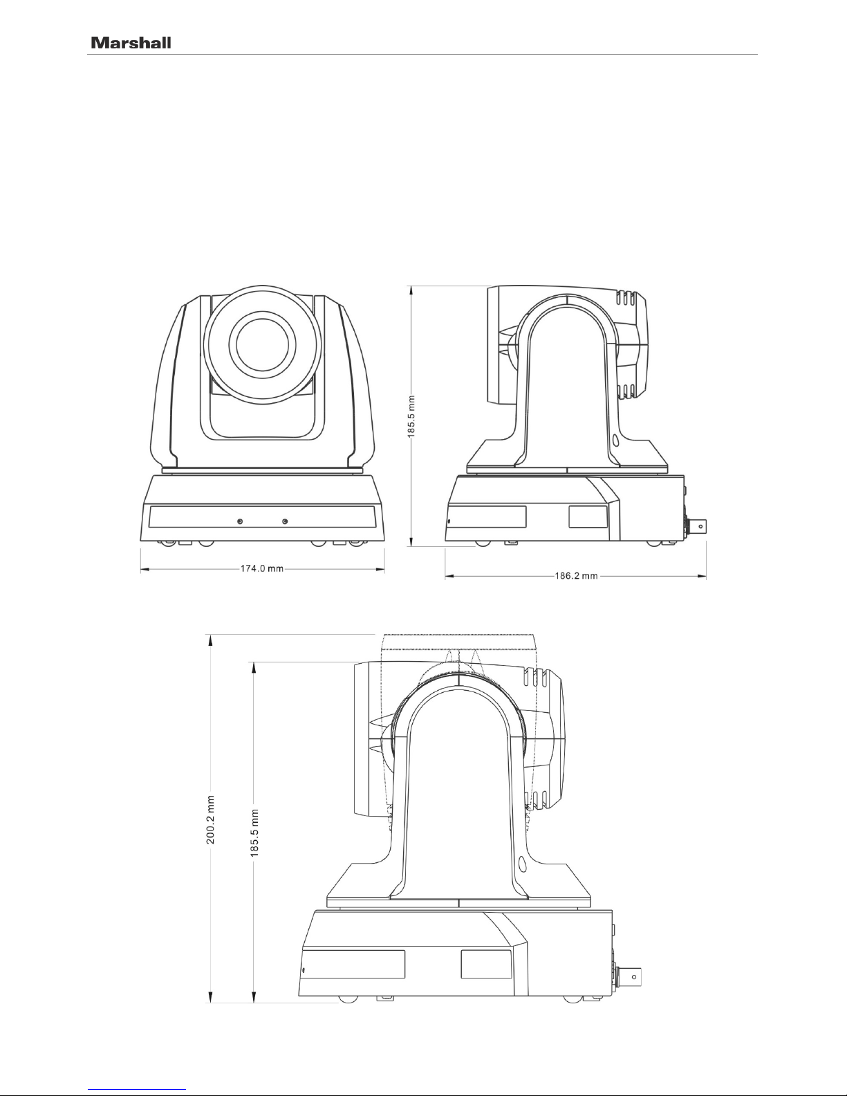
4.2.2.2 Camera Size
Length x Width x Height: 174 x 186.2 x 185.5 mm
Weight: 1.8 Kg
4.2.2.3 Max. rotat io n d imension of ca me r a
Page 9
CV620-IP / CV620-IPW
9 User Manual v.1
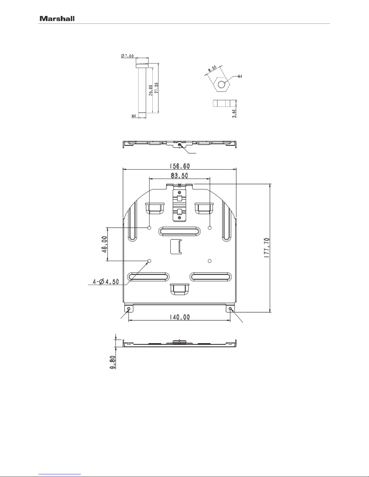
4.2.2.4 Size Diagram
1. Metal plate B - ceiling side
Metal plate B loc k i ng
screw
Metal plate B loc k i ng
bolt
Metal plate B - ceiling side
M3 threaded hole
M3 threaded hole
M3 threaded hole
Page 10
CV620-IP / CV620-IPW
10 User Manual v.1
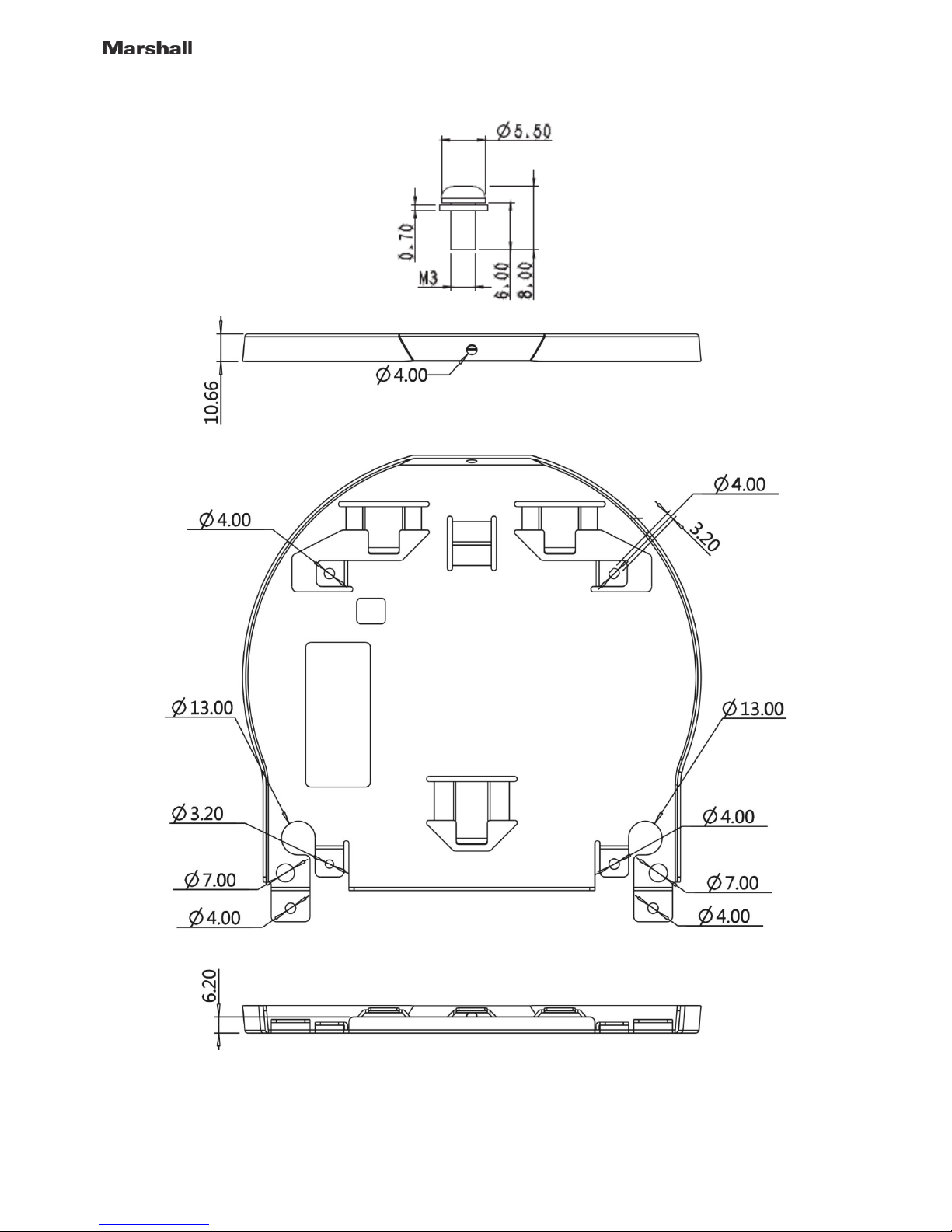
2. Metal plate A - machine side
Metal plate A - machine side
Metal plate A locking screw
Page 11
CV620-IP / CV620-IPW
11 User Manual v.1
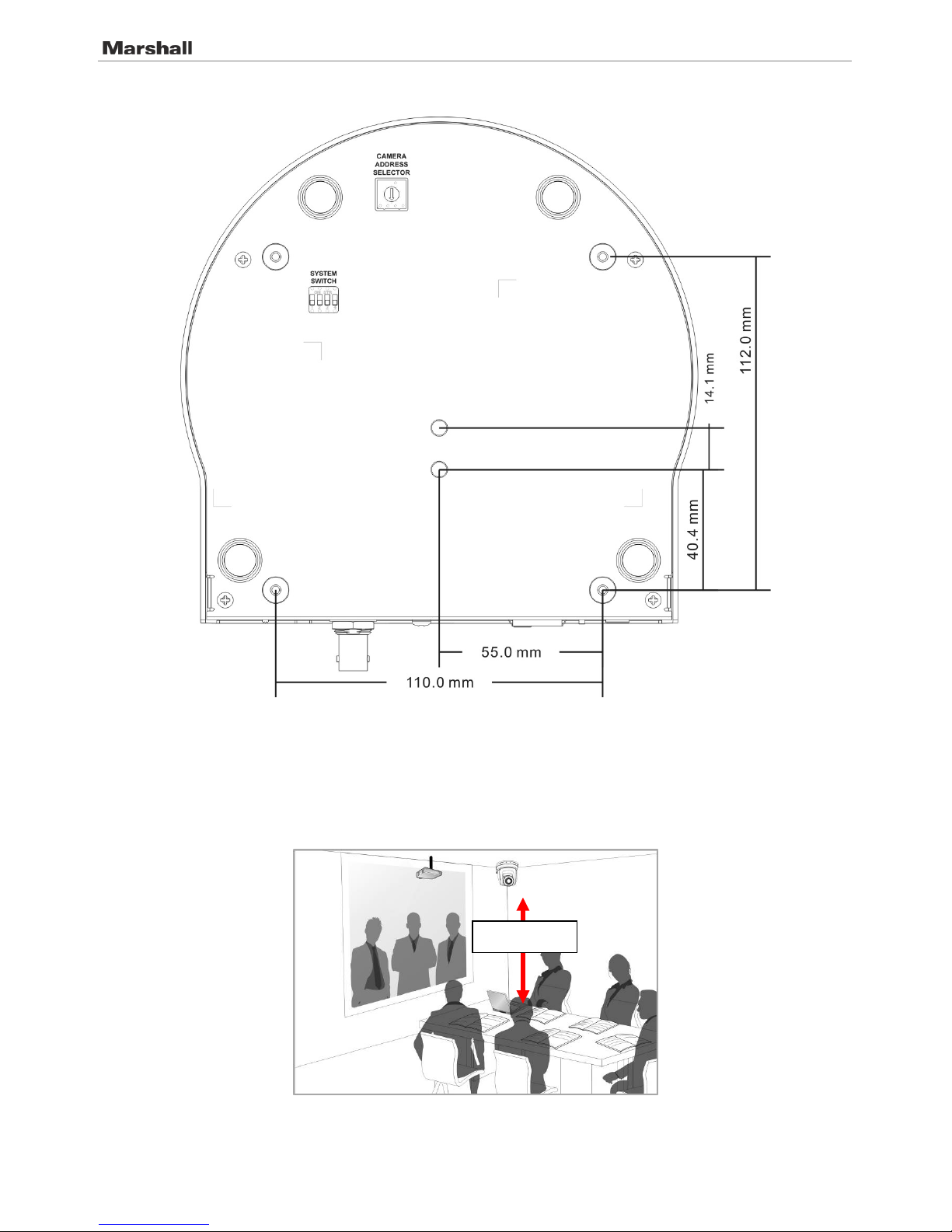
3. Bottom of machine
4.2.2.5 Precautions for installation
1. Before inst a lla t i on , please conf ir m the orientat i o n of th e m ac h i n e r e l at i ve t o th e o bj ect to be
captured
2. It is recommended that the machine should be set at a distance of more than 1 meter away from
the object to b e c a pt ured. Please a dj ust for a best d is ta nce accordin g to the magnif ication of the
lens
3. The machine (including metal plates) is weighed at about 2.5 kg . If it is to be install e d o n t he
ceiling, please use the hanger that has obtained UL security approval to prevent the machine
from falling.
1 meter↑
Page 12
CV620-IP / CV620-IPW
12 User Manual v.1
4. Please check whether the c amera is insta l le d s ecurely on a re g u la r b as is
4.2.2.6 Installation steps
1. Please adjust resolution on DIP switch at first
Note: Please refer to Chapter 8. DIP Switch Setting for the relevant descriptions on DIP
switch.
2. Fix the metal plate A on the machine base with 4 M3 silver screws
3. Lock the metal plate B on ceiling mounted hanger
※Caution:
(1) Please use the hanger that has obtained UL security approval
(2) Please reserve the hole for the connecting wires of the camera
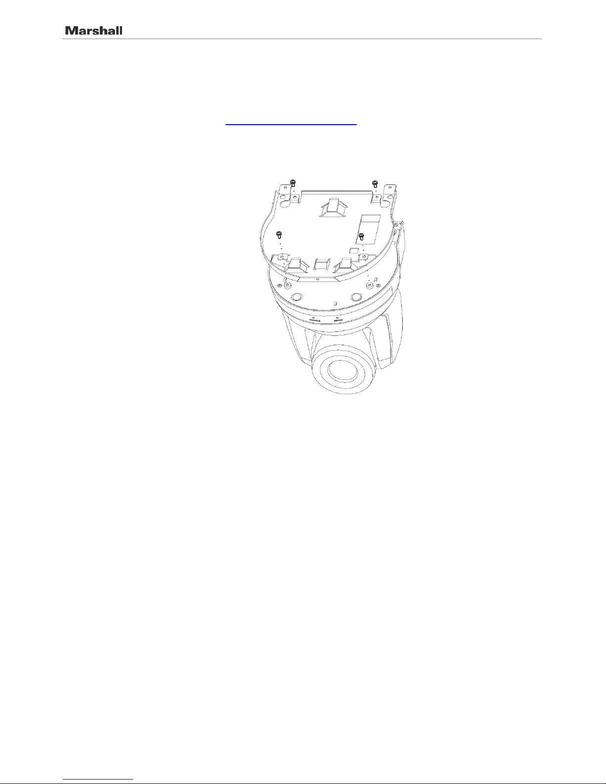
4. Combine the metal plate A and the metal plate B
(1) Push the metal plate A up to the ceiling and then to the right to latch the metal plate B
(2) And then secure with 2 M3 silver screws and 1 M3 black screw
Page 13

CV620-IP / CV620-IPW
13 User Manual v.1
black
screw
Page 14

CV620-IP / CV620-IPW
14 User Manual v.1
4.2.2.7 How to remove
1. Remove the connecting wires from the camera
2. Uninstall the camera together with the ceiling, loosen the three screws that fix the metal plates A
and B and push to the left to remove the machine
3. Then remove t he screws on th e ha ng er and the mach i ne
4.3 Connecting devices
4.3.1 Image Output
4.3.1.1 Connecting to PC ( v id eo conference)
<Remark 1> SDI supports the audio output of 48 KHz only.
4.3.1.2
Connecting to an HDTV/ com put er monitor (HDMI)
HDMI Cable
or
SDI Cable
MTU
Page 15

CV620-IP / CV620-IPW
15 User Manual v.1
4.3.1.3
Connecting to Internet
Note: CV620-IPW can be used with browsers, VLC and QuickTime after it is
connected to the Internet.
Router or Hub
Network cable
HDMI cable
Monitor or HDTV
Page 16

CV620-IP / CV620-IPW
16 User Manual v.1
4.3.1.4 Connecting AUDIO IN
Note: Set the [Audio In] in the OSD to reflect the input device
4.3.2 Controlling VCs wit h t he computer
4.3.2.1 Connecting to one c omputer for connecti on between VCs (RS-232 i n/ out )
Note: With RS-232 in/ ou t , at most 7 VCs can be connected.
4.3.2.2
Connecting to one computer for connection between VCs (RS-422)
Note: Please refer to 8.2 RS-422 connect io n fo r th e RS-422 connectio n in s tructions.
MIC or audio mi xer
Audio
Page 17

CV620-IP / CV620-IPW
17 User Manual v.1
Note: With RS-422, at most 7 VCs can be con n e cted.
4.3.3 Use of CV620-IPW with Internet Connection
4.3.3.1 Setup before use
Connecting the screen through HDMI output.
Press [MENU] on the Remote Control to display the OSD menu.
Shift down to [Ethernet] t o modify and confirm the IP addr ess
DHCP: Enable/disable the dynamic host configuration protocol
IP Address: Confirm or modify the IP address of CV620-IPW
Subnet mask: 255.255.255.0
Gateway: Pr es et 192.168.100.254
[Remark] Please m o d ify the above settings based on the LAN setting of the operating environment. To use
DHCP, please connect the CV620-IPW to LAN and then confirm IP address.
After completin g s e tt i ngs, press [MEN U ] to exit the OSD m en u.
After completing setting and confirming IP address, HDMI cable can be disconnected.
4.3.3.2 Start Us in g
Connect network cable to CV620-IPW network port to connect CV620-IPW to LAN.
Press [MENU] on the Remote Control to display the OSD menu.
Open the browser, and enter the URL of CV620-IPW in the address bar,
e.g.: http://192.168.100.150 (default IP address)
Enter administra tor’s acco u nt and passwor d
Account: admin (Default)
Password: 9999 (Default)
Subnet mask: 255.255.255.0
Gateway: Pr es et 192.168.100.254
[Remark 1] For details, please refer to Chapter 7 Netw o rk Functi on Setting s Desc ription.
[Remark 2] In addition to browsers, other software such as VLC and QuickTime can be used for operation.
Page 18

CV620-IP / CV620-IPW
18 User Manual v.1
Chapter 5. Remote Control and Setting Menu
5.1 Functions of remote cont ro l
Note: The below functions are listed alphabetically.
Item Description
,,,
Move the lens
Back Light Turn on/off back light c ompensation
Camera
select
Choose 1 ~ 3 of CV620-IPW
Focus-
Manual /
Far/Near
Turn on manual focus to adjust the focal
length
Focus-Auto Auto focus
Freeze Freeze the screen
Home-Enter Go back to the m ai n p ag e / Ex ecute
Info Status infor mation
L/R
Direction Set
L/R Direction / Normal
Menu Display OSD menu
Mirror Rotate the image (OFF / Mirror / Flip /
Rotate)
Pan/Tilt
Reset
Clear the Pan / Tilt setting
Picture Switch image effect (OF F / N E G / B l ac k &
White)
Power Power Switch
Preset Appoint an ID (0 ~ 9) to save the current
position data
Reset Appoint an ID (0 ~ 9) t o de l et e t he c ur r en t
position data
Zoom-Fast Adjust image size
Zoom-Slow Fine-tune image size
Page 19

CV620-IP / CV620-IPW
19 User Manual v.1
5.2 Setting Menu
Note: Press [Menu] on the remote contro l to enter the setting menu; the bold underlined values in the foll o wi n g
table are def au l ts .
1st Level
Major Items
2nd Level
Minor Items
3rd Level
Adjustment
Values
Function Descriptions
Exposure
Mode
1. Full Auto
2. Shutter Pri
3. Iris Pri
4. Manual
5. White Board
6. Smooth Auto
Exposure mode setting
Exposure
Comp.
On / Off
AE Level
Exposure
Comp. Level
-6~0~5
The value can be adjusted only after
Exposure Comp. is activat ed
Shutter Pri
60/30
mode
50/25
mode
Shutter priority setting
1/10000
1/10000
1/5000
1/5000
1/3000
1/3000
1/2500
1/2500
1/2000
1/1750
1/1500
1/1250
1/1000
1/1000
1/725
1/600
1/500
1/425
1/350
1/300
1/250
1/215
1/180
1/150
1/120
1/120
1/100
1/100
1/90
1/75
1/60
1/50
1/30
1/25
1/15
1/12
1/8
1/6
1/4
1/3
1/2
1/2
1/1
1/1
Page 20

CV620-IP / CV620-IPW
20 User Manual v.1
Iris Pri
1. F1.6
2. F2
3. F2.2
4. F2.7
5. F3.2
6. F3.8
7. F4.5
8. F5.4
9. F6.3
10. F7.8
11. F9
12. F11
13. F13
14. F16
15. F18
Iris setting
Manual Gain
1. 0dB
2. 2 dB
3. 4 dB
4. 6 dB
5. 8 dB
6. 10 dB
7. 12 dB
8. 14 dB
9. 16 dB
10. 18 dB
11. 20 dB
12. 22dB
13. 24dB
14. 26 dB
15. 28 dB
16. 30 dB
Manually set the gain
Manual Spee d
60/30
mode
50/25
mode
Manually set the shutter
1/10000
1/10000
1/5000
1/5000
1/3000
1/3000
1/2500
1/2500
1/2000
1/1750
1/1500
1/1250
1/1000
1/1000
1/725
1/600
1/500
1/425
1/350
1/300
1/250
1/215
1/180
1/150
1/120
1/120
1/100
1/100
1/90
1/75
1/60
1/50
1/30
1/25
1/15
1/12
Page 21

CV620-IP / CV620-IPW
21 User Manual v.1
1/8
1/6
1/4
1/3
1/2
1/2
1/1
1/1
Manual Iris
1. F1.6
2. F2
3. F2.2
4. F2.7
5. F3.2
6. F3.8
7. F4.5
8. F5.4
9. F6.3
10. F7.8
11. F9
12. F11
13. F13
14. F16
15. F18
Manually set the iris
Gain Limit
1. 8 dB
2. 10 dB
3. 12 dB
4. 14 dB
5. 16 dB
6. 18 dB
7. 20 dB
8. 22dB
9. 24dB
10. 26 dB
11. 28 dB
12. 30dB
Max. limit value of electron gain
Iris Limit
1. F1.6
2. F2
3. F3.2
4. F4.5
5. F6.3
6. F9
7. F13
8. F18
Max. limit value o f iris
WDR
1. Disable
2. 1
3. 2
4. 3
5. 4
6. 5
WDR settings
Page 22

CV620-IP / CV620-IPW
22 User Manual v.1
White Balance
Mode
1. Auto
2. Indoor
3. Outdoor
4. One Push WB
5. ATW
6. Manual
7. Sodium Lamp
8. 3000K
9. 4300K
10. 5000K
11. 6500K
12. 8000K
13. WideAuto
Select the color temperature mode
1. 4000k ~ 7000k
2. 3200k
3. 5800k
4. 1700k ~ 10000k
5. 1700k ~ 10000k
6. Custom
7. 2800k
8. 3000K
9. 4300K
10. 5000K
11. 6500K
12. 8000K
13. 3000k ~ 7000k
One Push
Trigger
ENTER
One push trigger
Manual Red 0~ C~128
Adjustable when the white balance
mode is set to Manual
Manual Blue 0~ C~128
Adjustable when the white balance
mode is set to Manual
Picture
Picture effect
1. Disable
2. Neg
3. B & W
Set the picture effect
Sharpness
0~ C~15
Adjust the sharpness of the im ag e
2D NR
1. Auto
2. Disable
3. 1
4. 2
5. 3
6. 4
7. 5
2D noise reduction settings
3D NR
1. Disable
2. Low
3. Typ
4. Max
5. Auto
3D dynamic noise reduction settings
Image Mode
1. Mode 1
2. Mode 2
3. Mode 3
4. Mode 4
5. Mode 5
6. Mode 6
7. Custom
The user may customize his/her
desired image mode.
Image Mode
Load
1. Mode 1
2. Mode 2
3. Mode 3
4. Mode 4
5. Mode 5
6. Mode 6
Adjustabl e wh e n t he image mode is
set to Custom. After selected, the
corresponding image m ode
parameters will be read an d a pp l i ed to
Custom
Brightness
0~ C~25
Adjustabl e wh e n t he image mode is
set to Custom
Contrast
0~ C~25
Contrast adj ustment; Adjustable wh e n
the image mode is set to Custom
Page 23

CV620-IP / CV620-IPW
23 User Manual v.1
Saturation
0~ C~25
Adjustabl e i n t he Custom Mode
Black Level
1. Disable
2. Type 1
3. Type 2
4. Type 3
5. Type 4
6. Type 5
Adjustabl e i n t he Custom Mode
Gamma
0~ C~3
Adjustabl e i n t he Custom Mode
Skin Tone
0~ C~5
Skin tone set t i ng , a dj ustable in the
Custom Mode
Pan Tilt Zoom
Pan/Tilt Limit
ON/Off
Turn on/off the angle limit s et t in g
Pan Right Limit
0~170
Limit the right angle
Pan Left Limit
-170~0
Limit the left angle
Tilt UP Limit 0~90
Limit the upward angle
Tilt Down Limit
-30~0
Limit the downward angle
Pan/Tilt Speed Preset/Low
Adjust Pan/Tilt Speed
Pan Flip
On/Off
Activate the reverse Pan command
Tilt Flip
On/Off
Activate the reverse Tilt command
Preset Speed
1. 5 per second
2. 25 per second
3. 50 per second
4. 100 per second
Set the rotation speed of the cradle
head when Preset is executed
PTZ Speed
Comp
On/Off
PTZ Speed Compensation
Dig-Effect
Mirror
1. Disable
2. Mirror
3. Flip
4. Mirror + Flip
Set the mode at which the image is
turned
Auto Focu s
AF Sensitivity
1. Low
2. Middle
3. High
Select the AF triggering speed. The
higher the speed is, the faster AF is
triggered
AF speed
Fast / Normal
Focus speed after AF triggering
AF Frame
Full Area/Center
Area
AF frame setting, when central area
was set as AF frame, focusing will be
on the center of the screen. When Full
Frame was set as AF frame, focusing
will be calculated based on the full
screen
Ethernet
DHCP
On/Off
Enable/D isa b l e DHCP setting usin g l ef t
and right arrow keys and pres s
[ENTER] to apply setting.
IP Address
192.168.100.150
Press [ENT ER ] to m odify the items ;
select the it em to be modified using left
and right arrow keys, and modify the
value using numeric keys.
Subnet mask
255.255.255.0
Press [ENT ER ] to m odify the items ;
select the it em to be modified using left
and right arrow keys, and modify the
value using numeric keys.
Page 24

CV620-IP / CV620-IPW
24 User Manual v.1
Gateway
192.168.100.254
Press [ENT ER ] to m odify the items ;
select the it em to be modified using left
and right arrow keys, and modify the
value using numeric keys.
System
Prompt
On / Off
Turn on/off the prom pt information on
the display
IR Receive
On / Off
Turn on/off the infrared reception
Motionless
Preset
On / Off
When the function is enabled, the
screen will Freeze when Preset is
executed. Freeze will be released after
Preset is completed.
Audio In
Line In/Mic In
Set Audio In
Audio Enable
On / Off
Turn on/off soun d o ut p ut
Audio Volume
0~10
Volume Setting
Encode
Sample Rate
1. 48 KHz(AAC)
2. 44.1 KHz( A AC)
3. 16 KHz(G. 711
4. 8 KHz(G.711)
Set the encode type and sample rate
SDI supports the audio out pu t of 4 8
KHz only.
Language
English / Chinese
Language
Output Mode
1. 1080p/60
2. 1080p/59.94
3. 1080p/50
4. 1080p/30
5. 1080p/29.97
6. 1080p/25
7. 1080i/60
8. 1080i/59.94
9. 1080i/50
10. 720p/60
11. 720p/59.94
12. 720p/50
Set output resolution
Protocol
Protocol V /
Protocol PD
Protocol V: VISCA
Protoco l P D: PELCO D
PD Address 1~ C~255
The Protoco l s e t to PD allows the
camera ID address to be ass i gn e d
Factory Res et On / Off
Resume the factory default setting
FW Upgrade
On / Off
Upgrade Firmware
Status
Display the current setting status
Page 25

CV620-IP / CV620-IPW
25 User Manual v.1
Chapter 6. Descriptions of Major Funct ions
6.1 I would like to switch to CV620-IPW
1. Press [Came ra 1 ~ 3] on the remote cont rol to select CV620-IPW.
Camera 1 ~ 3 is selected with IR SELECT.
6.2 I would like to save the current lens position data
1. Hold [P r e set + ID] on the remote control to save the current position data.
ID shall be a digit [0 ~ 9].
Use VISCA Command to store position data to [0 ~ 127]
6.3 I would like to clear the saved position data
1. Hold [R es et + ID] on the remote control to clear the given position data.
ID shall be a digit [0 ~ 9].
Use VISCA command to cle ar po s ition data stored in [0 ~ 127]
6.4 I would like to turn on the back light compensation function
1. Press [Back Light] on the remote control to turn o n or t ur n off th e bac k light compensation
6.5 I would like to adjust the shooting angle of the lens
1. Press [Tilt ] or [Tilt ] on the remote control to adjust the angle upward or downward.
2. Press [Pan ] or [Pan ] on the remote control to adjust the angle to right or left.
3. Press [Pan - Tilt Reset] on the remote control to reset the angle to the center point.
6.6 I would like to zoom in/out images
6.6.1 Adjust image size
1. Press [Fast +] on the remote control to zoom in images.
2. Press [Fast -] on the remote control to zoom out images .
6.6.2 Fine-tune image size
1. Press [Slow +] on the remote control to zoom in images.
2. Press [Slow -] on the remote control to zoom out im ag es.
6.7 I would like to adjust the focal length
6.7.1 Auto tune
1. Press [AF] on the remote control t o adjust automatically.
6.7.2 Manual focus
1. Press [MF] on the remote contro l to turn on the manual focus function.
2. Press Focus - [+] or Focus - [-] to adj ust.
6.8 I would like to adjust the AF speed
6.8.1 Adjust the AF Sensitivi ty
Triggering speed of focus. The higher the speed is, the faster focus is triggered
Page 26

CV620-IP / CV620-IPW
26 User Manual v.1
To shoot fast-moving objects, AF Sens it iv ity can be set to [High] or [Medium], which is applicable to
quick focus.
When the environment is too dark to enable auto focus or fixed objects have to be shot in different
brightness, AF Sensitivity can be set to [Low].
1. Press [MENU] to activate the setting menu.
2. Press [] or [] to select [Auto Focus].
3. Press [ENTER] to activ at e.
4. Press [] or [] to select [AF Sensitivity].
5. Press [ENTER] to activ at e.
6. Press [] or [] to select [High / Middle / Low].
7. Press [MENU] to exit.
6.8.2 Adjust the AF speed
The focus speed upon triggering AF Sensitivity
[Normal] (default): Image flickering may not occur
[Fast]: Fast focus speed
1. Press [MENU] to activate the setting menu.
2. Press [] or [] to select [Auto Focus].
3. Press [ENTER] to activ at e.
4. Press [] or [] to select [AF speed].
5. Press [ENTER] to activ at e.
6. Press [] or [] to selec t [Fast / Norma l] .
7. Press [MENU] to exit.
6.9 I would like to set the image mode
1. Press [Picture] on the remote control to switch [Off / Neg / B&W].
6.10 I would like to freeze images
1. Press [Freeze] on the remote control to freeze the current image on the display.
6.11 I would like to rotate the image
1. Press [Mirror] on the remote control to switch [Off / Mirror / Fli p / M irror + Flip].
6.12 I would like to change the camera direction
1. Press [ L/R Dir ectio n Set] on the remote cont rol to switch [L/R Direction / Normal].
6.13 I would like to display the current status
1. Press [Info] on the remote control to display the current status information. `
6.14 I would like to reset to the default value
Reset to default value using OSD menu
Press [MENU] [System] [Fac tory Reset] [On] [Enter] on the Remote Control and reset to
the default value
Page 27

CV620-IP / CV620-IPW
27 User Manual v.1
Chapter 7. Network Fu nction Setti n gs De sc r iption
7.1 Web System Requirements
Web Browser: Internet Explorer 8 ~ 11
7.2 Online IP Camera
7.2.1 Connecting to Internet
Two common connection methods are shown below
1. Connecting via switch or router
2. To connect directly through network cable, the IP address of the computer should be changed so
that it is on the same network se gment as the cam era; for inst anc e 192.168.100.x (preset for
camera)
Connection diagram
Change network settings
7.2.2 Use the web browser
1. Open the IE browser, and enter the URL of CV620-IPW in the addres s bar, such as:
http://192.168.100.150 (default IP address)
2. Enter admin is tr a t or’s accou nt and passwor d t o get started
Account: admin (Default)
Password: 9999 (Default)
Note: 1. “Web Plugin” must be installed before the first use. Please install the program after
downloading according to instructions on the screen (as shown in the following figure)
CV620-IPW
Switch or rout er
Computer
Network cable
Network cable
CV620-IPW
Computer
Network cable
Page 28

CV620-IP / CV620-IPW
28 User Manual v.1
2. Please login the computer as Administrator to install i t
3. After completing installation, please refresh the page.
7.2.3 Use RTSP player
In addition to browser, other RTSP methods can be used for connection, such as VLC and Quick Time
RTSP connection address:
RTSP main stream (h264)=>rtsp://VC IP Address:8557/h264
RTSP second stream (h264) =>rtsp://VC IP Address:8556/h264
RTSP second stream (MJPEG) or single stream in MJPEG=>rtsp://VC IP Address:8555/mjpeg
1. Open the software to enter URL: rtsp://192.168.100.150:8557/h264
7.2.4 Use RTMP connec tion
Support RTMP connection. If RTMP server is set up, RTMP connection function can also be opened
Please log int o CV620-IPW webpage to change RTMP of network setting as described in 7.2.2 Use the
Web Browser
Note: To upload to YouTube for online viewing, please refer to 7.3.9 Settings – Audio Setting and turn
on sound
Page 29

CV620-IP / CV620-IPW
29 User Manual v.1
7.3 Web Page Function Descripti on
7.3.1 Login Screen
Username: E nt er user accoun t
Password: En t er user passwor d
Select Language: Select language from
English, Tr adition al Chinese and Simplif i e d
Chinese
Remember password: Remember the
password so that you do not need to type it
next time
Login: Log into the administrator screen on the
website
7.3.2 Preview Screen
1. Information about image encodi n g form and resolution
2. Rotate camera angle
3. Zoom in/out
4. Preview window
5. Power off CV620-IPW
6. Apply/Set preset
7. Switch to Full Screen
8. Logout
1 2 3
4
5 6 7
8
CV620-IP
Page 30

CV620-IP / CV620-IPW
30 User Manual v.1
7.3.3 Account management screen
1. Enter new username and password
2. Set the permissions: Descripti o n for permissions is listed in t he fo l lo wi n g t a b le
3. Apply
4. List of accounts:
Edit: Change password and permission of new account
Delete: Delete new account
Note: Reference for User Permissions
User Type
Admin
Operator
Viewer
View images
Y Y Y
Settings
Y
Y
N
User accounts
management
Y
N N
7.3.4 Settings – Video Setting
1. Camera name: Change camera name on this page
2. Select rate and encoding
3. Storage setting; for advanced settings, see 7.3.5 Settings –Advanced Video Setting
1
2
3
4
CV620-IP
1
2
3
CV620-IP
Page 31

CV620-IP / CV620-IPW
31 User Manual v.1
7.3.5 Settings –Advance d Vide o S et ting
1. IP Ratio: Set IP Ratio, from 1 to 60
2. Force I Frame :
Check this item to insert IDR frame into specified series flow and apply its setting. User’s setting
will be reserved and displayed in GUI interface
3. Encode Preset :
Auto: Select between speed and quality depending on the encoding method used (e.g.
HIGH_SPEED mode for refresh rate of 60 frames per second and HIGH_QUALITY mode for
high image quality)
HIGH_SPEED: Refresh rate of 60 frames per second is available
HIGH_QUALITY: Higher image quality can be obtained.
SVC: SVC opened encoding mode is applicable to RTSP series flow of 8601, 8602, 8603 and 8604
ports, different refresh rate for different p or ts. See remark
4. Encode Prof i l e: Encoded Information
5. Preset Sa v e
Note: SVC connection addre ss: rtsp://VC IP Address:Port/h264
1. 60Frame : rt sp://VC IP Address:8557/h264, E.g.: rtsp://192.168.100.150:8557/h264
2. 30Frame : rt sp://VC IP Address:8601/h264, E.g.: rtsp://192.168.100.150:8601/h264
3. 15Frame : rt sp://VC IP Address:8602/h264, E.g.: rtsp://192.168.100.150:8602/h264
4. 7Frame : rtsp://VC IP Address:8603/h264, E.g.: rtsp://192.168.100.150:8603/h264
5. 3Frame : rtsp://VC IP Address:8604/h264, E.g.: rtsp://192.168.100.150:8604/h264
CV620-IP
Page 32

CV620-IP / CV620-IPW
32 User Manual v.1
7.3.6 Setting - camera
1. Rotate camera lens a ngle
2. Save/Read preset
3. Adjust image size
4. Adjust camera set t in gs. Please refe r to 7. 3. 7 S et tings - Advanced Camera Setting
5. Preset S a ve
7.3.7 Settings –Advanced Camera Settin g
1.. Exposure:
Mode: Select exposure mode
Exposure Comp. Level: Se lec t exposure compensation lev e l
Gain: Adjust gain restriction
Iris: Iris setting
1 2 3
4
CV620-IP
5
4
2
Page 33

CV620-IP / CV620-IPW
33 User Manual v.1
WDR: WDR settings
Shutter Speed: Shutter settings
2. White Balance:
Mode: Select the color temperature mode
Open Push Trigger: Single col or temperature ex ecution adjus tment
Manual Red/Blue: Manually adjust blue/red color temperature
3. Focus:
Mode: Select manual/automatic focus
Focus Range: Set focus range
AF Sensitivity: Set automatic focus sensitivity
AF Speed: Set automatic focus speed
AF Frame: Set automatic focus range
4. Mirror:
Mirror: Set automatic flip mode
7.3.8 Settings – Picture Set t in g
1. Picture Ef f ect: Set the p ic t ure effect
2. 2D NR: 2D nois e r e d uc t i on s et t in gs
3. 3D NR: 3D dynamic noise reduction settings
4. Image Mode: The user may customize his / he r desired image m ode
5. Image Mode Load: Adjustable when Image Mode is set to Custom, simi l ar to O S D
6. Black Level: Adjustable when Image Mode is set to Custom, similar to OSD
7. Gamma: Adjustable when I mag e Mod e is set to Custom, similar to OSD
8. Skin Tone: Skin tone settings; adjustable when Image Mode is set to Custom, similar to OSD
9. Brightness: Adjustable whe n Im ag e Mode is set to Custom, similar to OSD
CV620-IP
2
4
3
5
12
Page 34

CV620-IP / CV620-IPW
34 User Manual v.1
10. Contrast: Adjustable when Image Mode is set to Custom, similar to OSD
11. Saturation: Adjustable when Image Mode is set to Custom, similar to OSD
12. Sharpness: Adjust the sharpness of t he image
7.3.9 Settings – Audio Setting
1. Turn on/off sound
2. Set MIC In/Line In
3. Set Encode Type (ACC / G.711)
4. Set Enc o d e S am p le rate
5. Preset Save
7.3.10 Settings- Date/ Time Setting
1. Current camera date an d t ime
2. Set the Time: Manua l s e tt i ng /synchronous computer time/synchro n ous SNTP server t ime/time of
automatic adjustment of daylight saving
CV620-IP
1 2 3
4
CV620-IP
1 3 2
Page 35

CV620-IP / CV620-IPW
35 User Manual v.1
3. Preset Save
Note: SNTP server address: Please change in network setting
7.3.11 Setting -- Network and Por t Se tting
1. Network address of camera: Change of setting is available only when DHCP function of camera
is turned off; please turn off DHCP function using CV620-IPW
screen menu, and for setting of each item of screen menu, see 5.2
Setting Menu
2. Set RTMP: Set connection address of RTMP depending on RTMP Server setting
3. Set RTSP: Enable/Disable Multicast
Note: It is suggested to enable Multicast when the number of users online watching the live
image simu lt an e o us ly is more than 4.
4. Set SNTP: Set SNTP Server IP
5. Set HTTP port. The default Port value is 80
Note: Change of setting is avail able only when DHCP function of camera is closed
6. Preset Save
1 2 4
3 5 6
Page 36

CV620-IP / CV620-IPW
36 User Manual v.1
Chapter 8. DIP switch setting
Note: Please turn off the machine before changing DIP switch setting.
8.1 DIP SWITCH
8.1.1 OUTPUT Switch
Output Mode
Setting
Output Mode
Setting
1920x1080/60p
1920x1080/50p
1920x1080/30p
1920x1080/25p
1920x1080/60i
1920x1080/50i
1280x720/60p
1280x720/50p
1080/59.94p
1080/59.94i
1080/29.97p
720/59.94p
8.1.2 IR SELECT
ID
Setting
1
2 3
8.1.3 Camera Address Selector
Setting Function
Descriptions
0~7
ID 0~7
8~9
Reserved
Page 37

CV620-IP / CV620-IPW
37 User Manual v.1
8.1.4 System Switch
Setting
Function Desc riptions
DIP 1
RS-232C/RS-422 selector
OFF : RS-232C / ON : RS-422
DIP 2
Infrared signal output switch
OFF : Off / ON : On
DIP 3
Communicat i o n baud rate selector
OFF : 9600 / ON : 38400
DIP 4 Reserved
8.2 RS-422 Connection
8.2.1 RS-422 Pin Descripti on
Pin NO.
Function
1
RXD OUT -
2
RXD OUT +
3
TXD OUT -
4
TXD OUT +
5
GND
6
RXD IN -
7
RXD IN +
8
TXD IN -
9
TXD IN +
Note:
Please con nec t I N + to OU T + wh en connectin g to SONY products
For non-SONY products, it may be necess ary to connect IN+ to OUT-
Page 38

CV620-IP / CV620-IPW
38 User Manual v.1
8.2.2 Use RS-422 Connection
1. Hold the two sides of RS-422 connector and pull out in the direction shown by the arrow in the fig ure
below
2. Peel off a section of copper wire (AWG Nos.28 to 18) and insert it into the connector hole; then use flat
screw driver to fix it
3. Insert the wired RS-422 connector back to the camera. Now the connection is completed
Note: When RS-422 con nect ion is being used, do not us e R S -232C connection.
Page 39

CV620-IP / CV620-IPW
39 User Manual v.1
Chapter 9. Troubleshooting
This chapter describes problems you may encounter while using CV620-IPW. If you have questions , please refer
to related chapters and follow all the suggested solutions. If the problem still occurre d, please contact your
distributor or the service center.
No. Problems Solutions
1. Boot without power
signal
1. Make sure you have plugged in the power cord.
2. Make sure th e S er v ic e D I P swit c h is Off.
2. There is no im age
output from CV620-IPW
1. Check the power.
2. Check if DIP switch is properly set. Please refer to C h ap t er 8 DIP
Switch Setting for related settings.
3. Make sure the display supports the output resolution; in general, the
resolution is 1080p60/1080i60/720p60.
4. Replace the cables and make sure they are not faulty.
3. CV620-IPW image is
severely delayed
Please use 1080p or 720p 60/50 Hz signals rather than 25/30 Hz signals.
4. Not working after
changes to DIP Switch
setting
After compl e ti n g DI P Swi tch setting, u np l u g a nd r ec o n nect the power c or d
and turn on the machine to change the setting.
5. CV620-IPW cannot be
operated b y re mo t e
control
1. Please confirm if the Camera Select on the remote control can be used
together with the IR Select on CV620-IPW.
2. P l ease prevent C V 62 0-IPW from direct sunshine.
3. Make sure the energy-saving bulb and the IR touch screen are as far
as possible to avoid interference.
4. When several CV620-IPW are connected in the same area, the
operation of two remote controls at the same time may result in signal
interfere nce . It is r ecommended t o us e on e remote contro l o n ly.
6. The device cannot be
controlled with Codec
1. Please consult the distributor to make sure the firmware version is the
latest one. The steps to check version is as follows:
1.1 Press [MENU] on the remote control
1.2 Choose [Status]
1.3 Go to Page 5 of [System]
1.4 Make sure the firmware version is correct.
2. Make sure the connection is correct (RS-232/422 Input).
3. Make sure Sys t em Switch DIP 1 and D I P 3 are c or r ec t .
7. The device cannot be
controlled with RS232/RS422
1. Make sure the connection is correct (RS-232/422 Input).
2. Make sure Syst em Switch DIP 1 and D I P 3 are c orrect.
8. Whether the Internet
can be used for
operation
Please refer to Chapter 7 Network Function Description for the Internet
usage
Page 40

Marshall Electronics, Inc.
20608 Madrona Avenue
Torrance, CA 90503
Phone: (310) 333-0606 / (800) 800-6608
Fax: (310) 333-0688
www.marshall-usa.com
 Loading...