

Page 1
Broadcast A/V Division
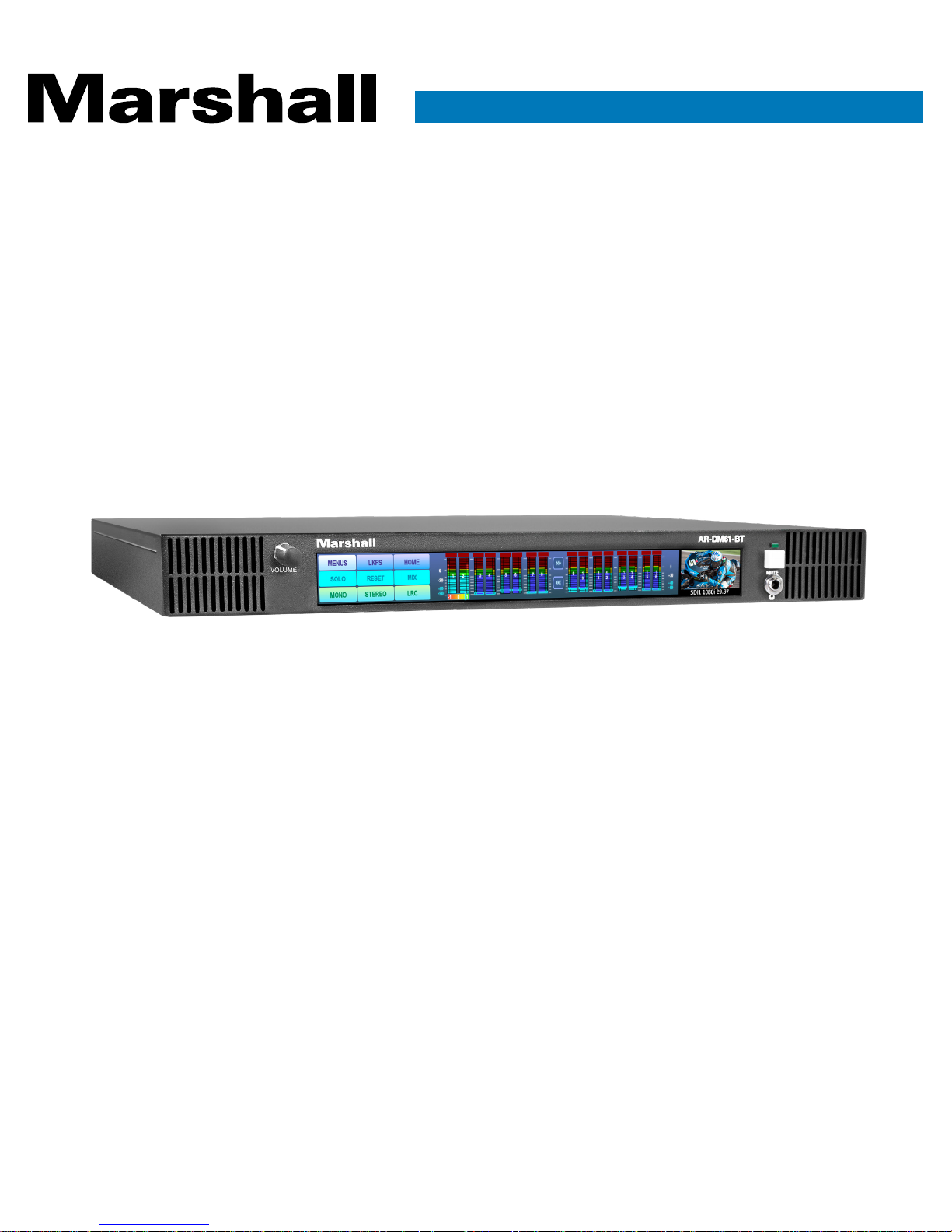
AR-DM61-BT
Multichannel Digital Audio Monitor
User Manual
[Firmware Version 0.43]
Page 2
AR-DM61-BT Manual
www.marshall-usa.com1 2
Table of Contents
Introduction
2. Package Contents
3. Quick Start Guide
4. Short Cut Buttons
5. Audio Metering Features
6. Video Display Features
7. System Settings
8. Options (Dolby® & Dante®)
9. Network Control – Initial Setup
10. Network Control – Operation
11. Dimensions
12. Specifications
13. Analog & AES Connector Details
Warranty
1. Features
03
04
07
08
09
10
12
14
15
22
23
24
25
03
The Marshall AR-DM61 audio monitor rack has an advanced design with the ability to
adapt to future needs. Its sonic performance is impressive, exceeding the capabilities
of many larger 2RU designs. In addition, the convenient front panel touch screen is the
first in the industry capable of providing high resolution 96-step audio metering or 64
channel side-by-side audio bars in the same unit. This breakthrough design removes
many limitations found in other products. Built-in support for most common input types.
Easy upgrades for Dolby, Dante / AES-67 options.
Page 3
AR-DM61-BT Manual
www.marshall-usa.com3 4
Touch Screen Convenience and Flexibility
• Eliminates most mechanical components
• Quickly switch display modes between multi-channel and high-precision
• Layout design not “frozen”
Integrated Video Display
• Provides visual confirmation of selected SDI input
• Displays selected audio channel numbers and video
format
High Performance Audio – Punches Above Its Weight
• Matches or exceeds most 2RU designs
• Enough “punch” for the noisiest server rooms
One Model Supports Multiple Input Types
• Two 3G SDI / MADI (auto-detection) Inputs - Standard
• 8 Channels AES / EBU Digital - Standard
• 8 Channels Analog Balanced - Standard
• Up to 64 Dante / AES-67 Channels - Option
• Dolby Decode - Option Plug-in Card
Network Control
• Web Browser Configuration
Compact 1RU Design Saves Rack Space
1. AR-DM61 main chassis
2. 24-volt DC universal power supply (120/240 VAC, 50/60Hz)
1. Features
2. Package Contents
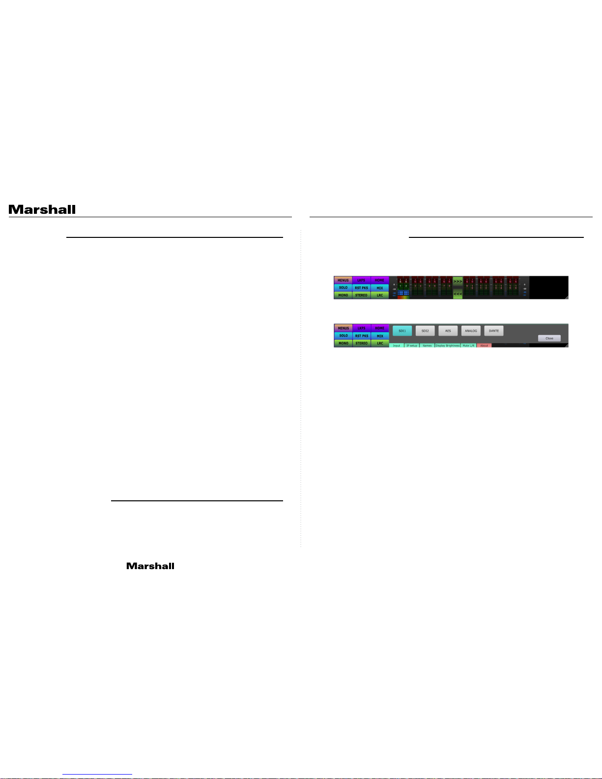
Powering up - Once power is initially applied, please allow approximately 30 seconds for the unit
to become functional. When the unit is ready for operation, the audio bars will display. You should
see something like this:
Basic operation – First, select the Menus button, then select the desired input from the selections
that appear.
Use the front panel Volume knob to adjust the sound to a comfortable level. The unit may be quickly
silenced by pressing the front panel Mute button.
Note: When SDI 1 or SDI 2 is selected as the input source, it will also be routed to the SDI / MADI
output connector on the back panel. When it is connected to a video monitor, it will “follow” the
input selection. This feature is intended as a convenience only and is not intended to replace a
production router. MADI output from this same connector is currently in development and not
enabled in this software version.
Monitoring Mode Selection - Quick access to common monitoring modes is available by selecting
MONO, STEREO or LRC depending on what you wish to hear.
MONO – Single audio channel selected and played from both speakers.
STEREO – A pair of audio channels is selected. The lower channel number will be heard from
the left speaker and the higher channel number from the right speaker. In this mode, a phase
“correlation” meter appears just below the HOME button.
LRC – Three channels are selected with the Center choice heard from both speakers.
3. Quick Start Guide
Page 4
AR-DM61-BT Manual
www.marshall-usa.com5 6
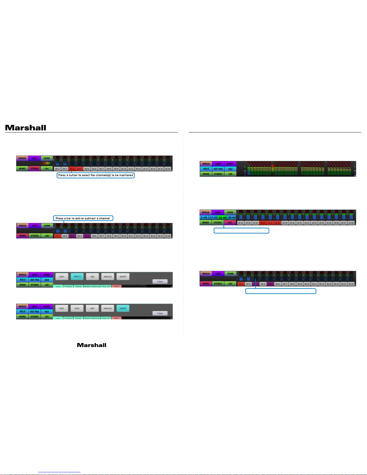
After selecting the desired monitoring mode, simply tap the BUTTON below the displayed audio
bars to select channel or channels to monitor. In the example below, STEREO mode has been
chosen and Channel pair 3 / 4 was selected for monitoring.
Mix Plus or Mix Minus Feature – By pressing a meter BAR, channels may be quickly added or
subtracted from a monitor mix.
For example: If it is then desired to listen to ONLY channel 3, press the meter BAR for channel 4
and it will drop out of the mix. Press any other bar or bars in the same group of 8 channels and they
can be ADDED to the mix.
In the picture below, MONO mode has been chosen then channels 3 and 5 have been ADDED to
the mix.
Note: Pressing the HOME button will return to the normal display and default to channel 1 / 2
monitoring.
MADI and Dante input types are handled somewhat differently from the other input types. MADI is a
standard feature and is input via either of the SDI input connectors. When MADI is detected on one
of the inputs, it will automatically appear in place of the SDI choice as shown below. In this picture,
a MADI source is connected to SDI input 2.
The Dante option is selected from the Menus page when the Dante upgrade board is present.
Sources are routed using the Dante Manager™ which is a free download from Audinate
®
.
MADI and Dante modes support up to 64 audio channels. All 64 can be displayed at once as seen in
the figure below. This can be quite useful finding “stray” or missing channels. However, because the
meter bars become very small, this is not the ideal display mode for selecting individual channels
or stereo pairs.
A group of 16 channels may be isolated by first selecting MONO, STEREO or LRC, then select one
of the channel ranges to narrow the focus to a group of 16 channels. From there it is quite easy to
monitor the desired channels in that group.
In the example below, LRC mode and channel group 33 – 48 have been selected. Channels 36, 37
and 38 are being monitored as Left, Right, Center from the speakers.
An arbitrary group of channels may be added or subtracted from the monitor mix by selecting the
meter bar above the desired channel(s). In the example below, MONO was selected then channels
3 and 5 were added.
NOTE: Only channels in a cluster of 8 may be monitored in this way. That is, any channels from 1
– 8 or 9 – 16, etc. may be combined but channels in different 8 channel groups, say 7 and 15 may
not be combined.
Click button to select a group
Click bar to add or remove a channel
Page 5

AR-DM61-BT Manual
www.marshall-usa.com7 8
4. Short Cut Buttons 5. Audio Metering Features
The Short Cut Buttons are the group of 9 buttons
to the left side of the display. The figure below
shows them in their most common configuration.
HOME – Selecting HOME reverts the unit to the default display mode. That is, vertical bars, STEREO
mode with Channels 1 & 2 selected as Left & Right.
LKFS – Produces a single horizontal bar representing the LKFS weighting and averaging algorithm.
(Currently under development). Pressing the RST PKS button on this screen restarts the averaging
process and resets the peak markers.
SOLO – Solo mode has much the same effect as MONO mode except that the display style does
not change. Tap on the desired meter bar to hear audio from that single channel. The selected
channel will be heard from both speakers.
RST PKS –The “Reset Peaks” button clears all audio bar peak hold “top hat” markers back to their
base position.
MIX – The MIX button enables a down-mix from multiple channels. The particular mix that is heard
when the MIX button is selected depends on settings made through the web browser interface (see
Network Control section below). When no changes have been made through the browser interface,
the default mix is assumed for 5.1 Surround with appropriate gain scaling. Custom mixes may be
created for each Input.
MONO, STEREO, LRC – These functions are described in Quick Start section above. They provide
monitoring of one, two or three source channels respectively.
The figure above shows the audio bars in their most common arrangement. A great deal of
information is available at a glance including: recent Over Range Amount, current audio Peak and
Average and Phase Correlation. Over Range and Peak markers are reset with the RST PKS button
in the Short Cut area.
Audio Bar Structure – Bars are grouped in pairs. The middle portion of each pair represents
the average audio level while the narrow portions show the peaks. Each has its own “peak hold”
markers. Bars representing the audio channels being heard on the speakers will be highlighted.
Below the selected audio pair, is a horizontal bar which is the phase correlation meter.
Phase Correlation Meter – The phase correlation meter registers to the right (Green) when the
selected pair of channels would have best “mono compatibility”. It will register in the center when
the two channels come from different sources or have little relationship to each other. Finally, it will
register to the left (Red) when one of the two channels has reversed polarity or 180-degree phase
shift compared to the other channel in that pair.
NOTE: The number of bars that will be displayed depends on the type of input selected.
SDI Inputs = 16 Bars displayed
AES and Analog = 8 Bars displayed
Dante and MADI = 64 Bars (can be subdivided to 16 channels using MONO, STEREO or LRC
monitoring selections)
Over Range Level
Peak Levels on Sides
Average Levels in Middle
Phase Correlation Meter
Page 6

AR-DM61-BT Manual
www.marshall-usa.com9 10
6. Video Display Features
7. System Settings
Selecting Channel s to be Monitored – Tap on the arrow symbols “>>>” to select different channels
to monitor.
Standard Display
High Precision Bars - It is possible to monitor any selected pair of audio channels in very high
precision (1db per step, 96 steps). Press on a pair of channels for just a moment and you will see a
display like this.
High Precision Display
A phase meter appears above the horizontal bars in this mode. Pressing the bars will switch back
to standard vertical multi-channel display mode.
The MENUS button provides access to Source Selection as mentioned previously. Smaller buttons
at the bottom of the screen provide access to System Settings. These operate as follows:
• Input – Press this button to highlight the currently selected Input if it is not already highlighted.
The selected source is highlighted pale blue. Sources that are not available (not connected to
the AR-DM61-BT) are highlighted in pink.
• IP Setup – Press this button to display the current Ethernet IP address and MAC address. (See
figure below) The addresses shown are examples, yours will likely be different. Remote setup of
the AR-DM61-BT is available using a web browser. Type the address exactly as it is displayed
including “:5000” into the browser search window. Convenient short-cut buttons allow for quick
IP se tup:
• SET to DHCP – Press this button to allow the AR-DM61-BT to automatically receive an IP
address from the attached network.
• SET to 10.0.0.219 – Press this button to quickly set the unit to a Fixed IP address compatible
with “Class A” networks. Press the SYSTEM RESET button to establish the new address.
• S ET to 19 2 .16 8 .1. 2 19 – Press this button to quickly set the unit to a Fixed IP address
compatible with “Class C” networks. Press the SYSTEM RESET button to establish the new
address.
• System Reset – Press this button to restart the AR-DM61-BT. User information such as
Input Names, Mixes, etc. will not be erased.
Note: Once a network connection is established with the AR-DM61-BT, specific IP address and
other changes may be made using the web browser interface. See “Network Control” sections
below.
• Program video is displayed when an SDI source is selected.
• A text overlay in the video window area shows the source type, resolution and frame rate. For
example: “SDI1 1080p 59.94”.
• When MADI or Dante are selected, the entire screen surface is occupied with 64 audio bars.
Note: Video display is optimized for 4:2:2 YUV color sampling. Colors may appear incorrect for
4:4:4 YUV or RGB sources.
Supported formats / frame rates:
480i 59.94, 576i 50
720p 50, 59.94, 60
1080i 50, 59.94, 60
1080p 23.98, 24, 25, 50, 59.94
Press Here for High Precision Horizontal Bar Use Arrows to Scroll to Other Channels
Touch these arrows to scroll to other channels Press and hold bars to return to normal display
Page 7

AR-DM61-BT Manual
www.marshall-usa.com11 12
• Names – For example, “IN 1” can be changed to “STUDIO 1”.
NOTE: At this time, name changes may only be made through the browser interface.
• Display Bright ness – Select this choice to adjust the front panel display brightness. Slide the
dot left or right to change the level.
• Mute L/R – Select this to listen to the sound from only one speaker. The selected channel will
be silenced. In this example, only the right speaker will be heard. Closing this screen will return
the monitor to normal stereo operation.
• About – Displays the firmware version and build date.
Dolby®
The AR-DM61-BT is compatible with the Dolby CAT 1100 decoder card and may be ordered installed
at time of purchase or the option may be added later. With this option, Dolby encoded audio on
either the SDI or AES inputs will be automatically identified and indicated on the front panel display
by the presence of the logo.
Here is an example of SDI with Dolby encoding detected on channel pairs 1 / 2, 3 / 4 and 7 / 8
To listen to the Dolby encoded audio, select the Dolby icon below the channel pair. In this example,
channel pair 1 / 2 have been selected and the MIX button has been pressed. To return to the original
display and stop Dolby decoding, select the icon in the upper right corner of the display.
The screen below, shows the AES input with Dolby detected on channel pair 5-6.
All normal listening selections like MONO, STEREO, LRC, MIX, etc. can be applied to the Dolby
decoded audio.
8. Options
Page 8

AR-DM61-BT Manual
www.marshall-usa.com13 14
Dante®
The AR-DM61-BT may be configured for 16, 32 or 64 channels of Dante audio. Ideally, this option
should be ordered at the time of purchase. While Dante support may be added at a later date, the
AR-DM61 may need to be returned to Marshall for component installation and programming.
The Dante option adds two additional RJ-45 Ethernet connectors on the back panel for Dante A&B
networks. To listen to Dante audio, select MENUS / DANTE. All channel assignment and routing to
the AR-DM61 are controlled via the Dante Controller™ application available from Audinate®.
When Dante monitoring is selected, up to 64 channels may be presented on the front panel display.
This is similar to the MADI display described above.
By selecting the STEREO button, groups of 16 channels may be displayed instead of 64 as shown
in the example below.
Network control of the AR-DM61
Deep configuration of the AR-DM61 is available via Ethernet using a standard Internet browser. Any
computer on the same network can access the unit.
First, locate the current IP address from the front panel of the AR-DM61 by pressing the MENUS
button then the IP Address button. The current IP address will appear at the top of the screen.
Next, type this complete address as it appears including the port number “:5000” into a web
browser and press Enter. (Example: 192.168.1.10:5000)
You should see a screen like this one.
Note: Windows 10 now limits Internet Explorer features. Some restrictions now apply in Safari as
well. Please use Edge, Chrome or Firefox.
9. Network Browser Control - Initial Setup
Page 9

AR-DM61-BT Manual
www.marshall-usa.com15 16
Functions:
• Naming – Allows custom names for sources. For example: Change the default name “IN 1” to
“STUDIO 1” or “SERVER 5”, etc.
• Mix – Create down-mixes that will take effect when MIX button on the AR-DM61 front panel is
selected. Each input type can have it’s own custom mix.
• IP Setup – Setup network connection type, either DHCP mode or Fixed IP address
• Touchscreen Calibration – Initiate touchscreen calibration to align buttons with icons.
• ARDM Status – Shows current operating voltages and temperatures inside the AR-DM61
• Firmware Update – Allows updating software via Ethernet.
NAMING
Click on Naming to see the screen below. Source names may be changed by simply highlighting
(turns blue) the default name such as “IN 1” with the new name “LEFT”, click on an adjacent cell
like IN 3 to complete the edit then click on the Update ARDM button. The message “Update
Successful” will appear.
The new name will take effect after the front panel HOME button is pressed or a new input source
is selected.
In this example, the meter names have been changed to “LEFT” and “RIGHT”.
Tip: Entire channel groups may be renamed at one time. Type the names
into a spreadsheet row, highlight the names, select COPY. On the AR-DM61
page, highlight input #1 in a group and select PASTE. Up to 64 names may
be pasted in one row. Likewise, existing channel names may be copied from
the AR-DM61 and saved back to a spreadsheet for use later by reversing
the process. Use all CAPS to improve readability.
MIX
Separate mixes are created for each input source. The MIX created on this page is heard ONLY
when the MIX button on the front of the AR-DM61 is pressed. Channels that are included in the
mix will be highlighted in Green and have the letter L, R or C. Channels that are not included will be
highlighted in Red and say OFF.
Selecting “L” means the sound will come out of the AR-DM61 left speaker, “R” means the sound
will come out of the right speaker and “C” means the sound will come out of both left and right
speake rs.
In the example below, the AES source has been setup for a 5.1 channel down-mix. Channels 4,7
and 8 have been turned OFF and the channel names have been edited.
Note: Downmixes may be fine-tuned by adjusting the gain values shown in the input fields at the
bottom. Gains are shown as negative numbers to represent their relative strength in the mix. Setting
a positive number will cause that input to appear on ALL output channels. A value of -90 = OFF.
When a MIX is selected on the AR-DM61 front panel, it is also applied to the rear panel Analog
output (8 channel group).
• Add or remove channels - Simply click on channel buttons to add or remove them from the
mix. (Cycle through choices of: L, R, C or OFF).
• Presets - There are presets provided for common mixes. Click one of the Gray buttons on
the left to select presets: 5.1, 7.1, All 0db or User. Mix values are pre-established but can be
“trimmed” by typing a new dB level below the chart. If a channel is OFF, there will be no mix
value shown. Selecting L, R or C for that channel will open a new mix value window. A value of
0.0 is full level (no gain reduction). A value of -90.0 is equivalent to OFF.
• Activat e - When the desired mix has been created, scroll to the bottom of the page and click on
Update ARDM to send the changes to the AR-DM61 or click Cancel to discard the changes.
10. Network Control - Operations
Page 10

AR-DM61-BT Manual
www.marshall-usa.com17 18
• Pressing the HOME button on the AR-DM61 front panel will update it. When the MIX button is
next used, the new mix will be applied.
• Mix Shortcut – An entire group of 8 channels may be quickly set to a particular mix with just
two mouse clicks. This is especially helpful when working with large numbers of channels as is
common with MADI or Dante.
In the example below, MADI channel 17 was selected, then the “Set 7.1” button was clicked. The
whole row is now set for 7.1 mixdown.
IP Setup
This page offers two choices depending on the “slide switch” at the bottom. When the switch is set
to DHCP, you will see the image on the left. When it is set to Fixed, you will see the image on the
right. In DHCP mode, the IP address will be assigned by a router or DHCP server on the network.
In Fixed mode, IP address, Netmask and Gateway may be typed into the available fields to create
a Fixed IP Address. Once you have changed the mode or altered the address, click on the Update
ARDM button to transmit the change to the AR-DM61. This will cause the unit to restart (allow
30 seconds). Note: When the IP address has been changed, the browser cannot communicate
with the AR-DM61 until the new address is typed into the browser address window since the old
address will no longer work.
Page 11

AR-DM61-BT Manual
www.marshall-usa.com19 20
Touchscreen Calibration
This function is rarely needed. When the AR-DM61 is mounted at an angle or in a hard-to-reach
location relative to the operator, the buttons may appear to not match the location that is being
touched. Using the Touchscreen Calibration process, the button graphic and the active screen
location may be aligned. There are just two choices on this page:
• Start Calibration
• Use Default Calibration
When Star t Calibration is selected, a small timer circle appears in the center of the front panel
display and a “+” symbol appears in the upper left corner of the display. Tap on the “+” and a new
“+” will appear in the upper right corner. Continue to tap on these symbols until all four corners of
the screen have been touched. At this point, a message will appear on the web browser. “Tou ch
Screen Calibration Successful….Please Restart ARDM”. Restarting the AR-DM61 will activate
the new calibration.
To restart the unit, Select the MENUS button then select either IP Setup or About and press
System Reset.
ARDM Status
This page is used to monitor the AR-DM61 internal operating Voltages and Temperatures. Operating
peak and average voltages and currents are displayed. Also software and FPGA firmware versions.
This information is primarily useful for system test and troubleshooting.
Page 12

AR-DM61-BT Manual
www.marshall-usa.com21 22
Firmware Upgrade
To upgrade the AR-DM61, first obtain an update file from the Marshall Electronics website here:
Update files are currently not posted on the website. Please contact your Marshall Electronics
representative for the latest firmware.
Save this file to your computer then click on the Choose Files button (see below) and browse your
computer for the update file and select it. The correct file will have the extension “.gz”. Next, click
on the Upload Firmware button. This will cause the AR-DM61 front panel to go blank and the
upgrade process will begin.
After approximately 2 minutes, the unit will restart and the update process will be complete. The
installed firmware version and build date can be confirmed by pressing the front panel MENU
button then the About button.
11. Dimensions
Page 13

AR-DM61-BT Manual
www.marshall-usa.com23 24
12. Specifications 13. Connector Details
Model Name
Tec hni ca l
Mechanical & Electrical
Video Input Connections
Video Formats Supported
Audio Input Connections
Audio Output Connections
USB 2.0 Port
Network Connections
Dante Network Connection
Housing
Dimensions [H x W x D]
Weight
Mounting
Included Power supply
DC Power consumption
Operation temperature
Storage temperature
Relative humidity
ESD protect ion
2 x 3G SDI with looping output
SDI up to 1080p50, 59.94,60
SDI Embedded 16 channels (two inputs)
Analog 8 channels balanced v ia 25-pin DSub (Tascam format)
AES 8 channels digital via 25-pin DSub ( Tascam format)
Dante up to 64 channels via dual IP (option board)
MADI 64 channels (auto selected if pres ent on either SDI input)
AES/EBU 8 channels via 25-pin DSub ( Tascam format)
Analog 8 channels balanced v ia 25-pin DSub (Tascam format)
Product Test / Service
Ethernet 100 Base-T, supports DHCP or Fixed Addressing
Dual 1GB Ethernet (included with Dante Option)
Dual 1Gigabit Ethernet. Supports Dual A /B Network Operation
Metal enclosure
1.75” X 17.36” x 14.3” / 4.45 cm x 44.0 cm x 36.3 cm
8.8 lbs / 4 Kg
Integral “ears” for standard 19” rack mount
DC 24-Volts 6.25 Amps 4-pin XLR connector
20 Watts Typical
0~40 C [32~104 F]
-20~60 C [-4~140 F]
20~90% RH [no condensation]
Human body model — ±15kV [air-gap discharge] & ±8kV [contact
discharge]
AR-DM61
AES/EBU Input / Output Connector
Analog Balanced Input and Output Connectors
Connections are Tascam® format and compatible with Mogami breakout cable model: Gold
DB25-XLRM available in various lengths from Marshall Electronics. See link below for details:
http: //www.mogamicable.com/category/products/gold-AES_TD_DB25-XLR.php
Page 14

Warranty
Marshall Electronics warranties to the first consumer that this device will, under normal use,
be free from defects in workmanship and materials, when received in its original container, for
a period of two years from the purchase date. This warranty is extended to the first consumer
only, and proof of purchase is necessary to honor the warranty. If there is no proof of purchase
provided with a warranty claim, Marshall Electronics reserves the right not to honor the warranty
set forth above. Therefore, labor and parts may be charged to the consumer. This warranty
does not apply to the product exterior or cosmetics. Misuse, abnormal handling, alterations or
modifications in design or construction void this warranty. No sales personnel of the seller or
any other person is authorized to make any warranties other than those described above, or to
extend the duration of any warranties on behalf of Marshall Electronics, beyond the time period
described above.
Due to constant effort to improve products and product features, specifications may change
without notice.
20608 Madrona Avenue, Torrance, CA 90503
Tel: (800) 800-6608 / (310) 333-0606 • Fax: 310-333-0688
www.marshall-usa.com
support@marshall-usa.com
V.1. 0
 Loading...