

Page 1

1 2 3 4 5 6
1. LOUDSPEAKER OUTPUTS
WARNING! Never use the amplifier without a load
attached!
There are two parallel loudspeaker output jacks
provided for connection to the internal speakers or
extension cabinet. Please always ensure that the
amplifier's output impedance selector is set correctly
(see item 2) and ALWAYS ensure you use good quality
speaker (unshielded) cables. NEVER use guitar (shielded)
cables.
Always use a non-screened Marshall approved speaker
lead when connecting an extension cabinet to these
units.
2. OUTPUT IMPEDANCE SELECTOR
Matches the amplifier’s output to the load (speaker)
impedance.
Your 1987X-PW should be completely powered down
before the Output Impedance Selector is turned.
As is the case with any Marshall all-valve amplifier it is
imperative that: a) the amplifier is connected to a load
whilst in operation and b) the impedance selected on
the amplifier matches the total impedance of the
extension speaker cabinet(s) being used. The two
internal speakers are 16 Ohms each.These are wired in
Registered Charity Numbers:
216401 & SC037717
parallel giving an overall impedance of 8 Ohms;
therefore the output selector should be set to 8 Ohms.
If an additional 8 Ohm extension speaker cabinet is used
in conjunction with the internal speakers the output
selector should be set to 4 Ohms.
4. MAINS INPUT
Your amp is provided with a detachable mains (power)
lead, which is connected here. The specific mains input
voltage rating that your amplifier has been built for is
indicated on the back panel. Before connecting for the
first time, please ensure that your amplifier is compatible
Note: No additional extension speaker cabinet with
impedance lower than 8 Ohms should be used in
conjunction with the internal speakers.
Failure to comply with any of the points raised in this
section will result in damage to the amplifier.
with your electricity supply. If you have any doubt, please
get advice from a qualified technician. Your Marshall
dealer will help you in this respect.
5. MAINS FUSE
The correct value of mains fuse is specified on the
rear panel of the amplifier.NEVER attempt to
3. MAINS SELECTOR
bypass the fuse or fit one of the incorrect value.
Matches the amplifier’s mains transformer to the
incoming mains voltage.
6. H.T. FUSE
The correct value of this H.T. fuse is specified on
Your 1987X-PW should always be completely powered
down before the mains selector is turned.
the rear panel of the amplifier. NEVER attempt to
bypass the fuse or fit one of the incorrect value.
WARNING! ALWAYS ensure that this rotary selector
is set to the correct mains voltage applicable for the
country where the 1987X-PW is being used. If you do
not know, consult your authorized Marshall dealer.
Note: This equipment has been tested and
found to comply with the requirements of the
EMC directive (Environments E1, E2 and E3 EN
55103-1/2) and the Low Voltage directive in the E.U.
Adjusting the selector from 230V to 120/100V or viceversa will require the mains fuse (item 5) to be changed
to the correct value as detailed on the rear panel.
EUROPE ONLY - Note: The Peak Inrush
current for the 1987X-PW is 26 amps.
With every 1987X-PW sold Marshall will make a sizable donation to the Childline charity. Providing help
and support to those children who need it, Childline is a vital service and one that relies heavily on private
donations to operate. It is with great pleasure that both Marshall and Paul Weller,through the creation of
the 1987X-PW, have agreed to support a charity that has such a positive effect on those who turn to it.
Marshall Amplification plc
Denbigh Road, Bletchley, Milton Keynes, MK1 1DQ, England.
Tel : +44 (0)1908 375411 Fax : +44 (0)1908 376118
www.marshallamps.com
Whilst the information contained herein is correct at the time of publication, due to our policy of constant improvement
and development, MarshallAmplification plc reserve the right to alter specifications without prior notice.
BOOK-00092-00 / 12 / 08
Technical Specification
Power Output - 50W RMS
Size - 740mm x 610mm x 265mm
Weight - 30.2 kg
LawrenceWatson
©
photo
Page 2
Introduction
The Marshall reputation has been built upon many things, but our longevity
comes mainly as a result of the continual relevance of the concepts behind the
design and build of our amplifiers. Added to this are solid workmanship, reliability,
stylish looks, and above all – great tone.
One of the most versatile Marshalls ever made, the Lead and Bass 50 watt combo, was offered for
sale through Mail Order from 1973 through 1976. Its original model number was the 2100 and was a
revolution in its day, combining one channel from a bass amp and one from a lead amp. Produced in fairly
low numbers, these combos are now much sought after for their simplicity of operation and superb natural
valve tone. The continual fascination and love that many guitarists show for our vintage amplification is a
testament to just how relevant and important these models still are today.
Achieving the beautifully organic and vibrant overdrive which is their trademark, can only be done in one way – crank’em
up! The result is pure majestic tone, uncluttered by unnecessary circuitry. With solos this produces a big, round, warm
sustain, full of classic character. With chord work you get a bark and percussive attack with a natural sounding break up,
which allows each note to ring out in a glorious musical crunch.
Like all Marshalls re-issues the 1987X-PW Lead and Bass Fifty Combo is as faithful as possible to the originals in terms of
construction and tone. Hand-crafted in the UK these superb units feature finger-jointed cabinets of birch plywood, hand-welded
chassis’s,hand-wired transformers, potentiometers and valve bases and the highest quality PCBs and components.
The Lead Bass Fifty has been
my main amp for the last ten
“
years or so, nothing comes
close to it, till now
”
From Jim Marshall
I would personally like to congratulate you for
choosing this incredibly special amplifier from
Marshall - the Lead and Bass 1987X-PW.
As you have heard the 2100 was initially launched in
1973 and has been the work-horse of many a guitarist
seeking the best of both lead and bass worlds. The
warm yet attacking tone created from these amps
proved extremely popular with the emerging generation
of guitarists and, I’m pleased to say,means that the Lead
and Bass 50 is still held in high regard today. One
guitarist who favours the 2100 just happens to be one
of the most respected and influential singer/songwriters
of recent times - Paul Weller.
I feel very fortunate to have enjoyed many years of
friendship and associations with some of the
most talented guitarists in living memory. The
fact that an artist of Paul’s calibre chooses a
Marshall is a very humbling feeling indeed. So
to celebrate both our long standing musical
partnership and Paul’s 50th birthday, I asked
the Marshall team to create a special Limited Edition amplifier based on the
2100 Lead and Bass 50 Combos. In response they have produced an amp
brimming full of vintage tone and style, indicative of the ‘Mod Father’ himself.
Apart from our love of music, both Paul and myself are committed to
raising money for very worthy causes. In purchasing this amplifier you
have ensured a substantial donation will be made by Marshall to the
Childline charity. Offering help and advice to children who need it
most, Childline is a vital service to the young and one which we are
proud to support.
All 50 of the 1987X-PW amplifiers have been hand-built in the UK
by our highly skilled staff on the Marshall factory floor. Their
attention to detail, craftsmanship and exacting standards have
been the foundation on which Marshall’s reputation has been
built, so you can rest assured that your 1987X-PW will stand the
test of time.
I sincerely hope that your new amplifier brings you years of
guitar playing pleasure and enjoyment. Welcome to the family.
Yours Sincerely
Dr Jim Marshall OBE
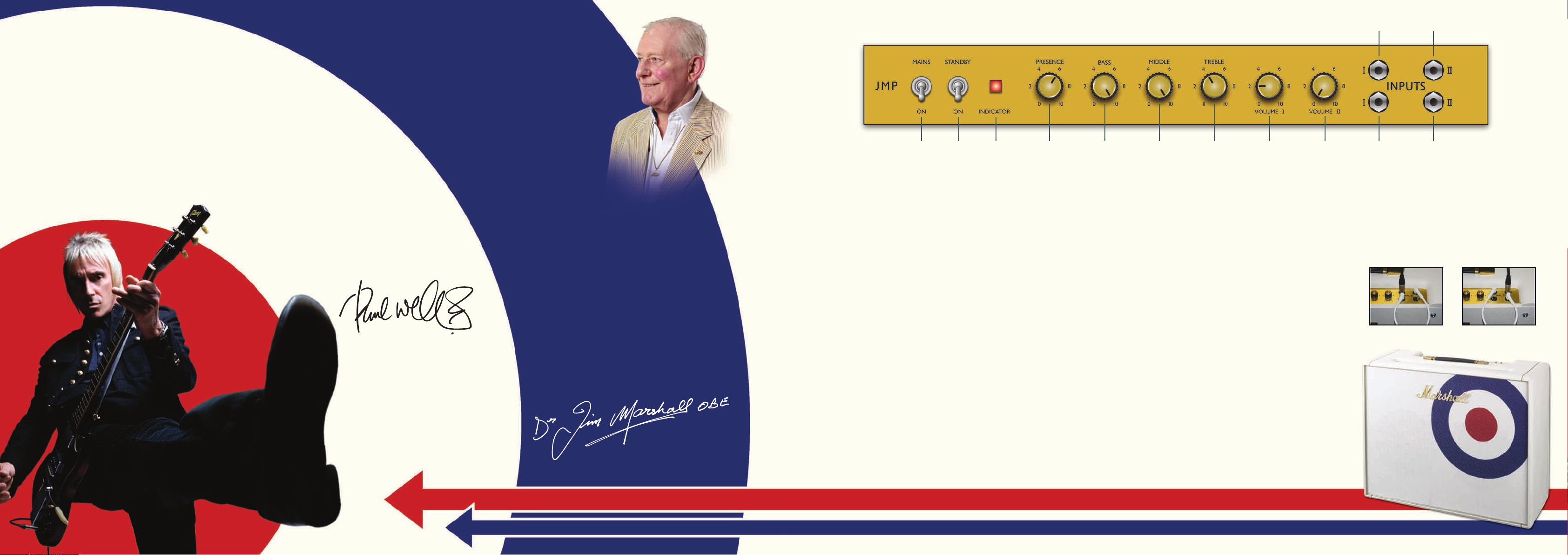
1 2 3 4 5 6 7 8 9 11
1. POWER SWITCH
This is the On/Off switch for mains power to the
amplifier.
Note: Please ensure the amplifier is switched off and
unplugged from the mains electricity supply whenever it
is moved.
2. STANDBY SWITCH
The Standby Switch is used in conjunction with the
Power Switch (item 1) to ‘warm up’ the amplifier before
use and to prolong the life of the output valves.
When powering up the amplifier always engage the
Power Switch first, leaving the Standby switch on
‘Standby’. This allows the application of the voltage
required to heat the valves to their correct operating
temperature. After approximately two minutes the
valves will have reached the correct operating
temperature and the Standby Switch can be engaged.
In order to prolong valve life, the Standby Switch alone
should also be used to turn the amplifier on and off
during breaks in a performance. Also, when switching
off, always disengage the Standby Switch prior to the
main Power Switch.
3. INICATOR
The Indicator will light up when your amplifier is
receiving the correct mains power and is switched on. It
will not be lit when the amplifier is switched off and/or
is not receiving mains power.
4. PRESENCE CONTROL
This control operates in the 1987X-PW’s power section
and adds high frequencies to your sound by altering the
power amplifier’s negative feedback. Turning this control
clockwise adds more edge and ‘sparkle’ to your sound,
making it crisper and more cutting.
5. BASS CONTROL
This adjusts the bottom end, turning it clockwise
increases the amount of low frequencies in the sound.
6. MIDDLE CONTROL
This adjusts the level of those all-important mid-range
frequencies. Turning it clockwise increases the mids and
fattens your sound, giving it more punch. Turning it
anticlockwise reduces the mids.
7. TREBLE CONTROL
This adjusts the top-end. Turning it clockwise increases
the amount of high frequencies (treble) present in the
sound, making your tone brighter.
Note: The following four controls - PRESENCE (item
4), BASS (item 5), MIDDLE (item 6) & TREBLE (item 7) are all shared, meaning that they all work on both
Channel I and Channel II. The Treble, Middle and Bass
controls are highly interactive and altering one control
can change the way the other two behave. For this
reason, experimentation is recommended.
Paul’s Preferred settings, as shown on the panel above:
P = 6, B = 10, M = 10,T = 4,VI = 2,VII = 0
8. VOLUME I
This controls the overall output level of Channel I,
turning it clockwise increases the volume. This is the
1987 super-lead channel and is voiced for a higher treble
response than Channel II.
9. VOLUME II
This controls the overall output level of Channel II,
turning it clockwise increases the volume level. This is
the 1986 super-bass channel and is voiced for a 'bass',
flatter response.
10. HIGH SENSITIVITY INPUT FOR
CHANNEL I
This is the ‘high sensitivity’ guitar input for Channel I –
the “Lead” channel is the brighter of the two channels and is the most commonly used input. Always use a high
quality screened guitar lead.
11. LOW SENSITIVITY INPUT FOR
CHANNEL I
This is the ‘low sensitivity’ guitar input for Channel I. It is
6dB lower in volume than the ‘high sensitivity’ input and
has a darker sound as well due to its significantly lower
input impedance.
12. HIGH SENSITIVITY INPUT FOR
CHANNEL II
This is the ‘high sensitivity’ guitar input for Channel II,
the so-called ‘Bass’ channel.
13. LOW SENSITIVITY INPUT FOR
CHANNEL II
This is the ‘low sensitivity’ guitar input for Channel II. It
is 6dB lower in volume than the ‘high sensitivity’ input
and has a darker sound as well due to its significantly
lower input impedance.
Performance Note: Bridging or ‘jumping’
the two channels
Because both Channels of the 1987X-PW have the
same number of gain stages (two) and are therefore in
phase with each other, it is possible to bridge them
together (‘slaving’,‘jumping’, ‘linking’ or even ‘daisychaining’) and use them both at the same time. Doing
this enables you to expand upon the amp’s tonal
possibilities by mixing the two channels together.
10 12
13
The most common way of doing this is to plug your
guitar into the top (high sensitivity) input of Channel I
and then run a short ‘jumper’ guitar cable (i.e. a
screened cable) from the Channel I’s bottom (low
sensitivity) input to the top (high sensitivity) input of
Channel II. (fig. 1)
The ‘reverse’ is also possible – namely plugging your
guitar into Channel II’s top input and then running the
‘jumper’ cable from Channel II’s bottom input to
Channel I’s top input. This less common approach can
yield some interesting tonal variations. (fig. 2)
Fig. 1 Fig. 2
photo©LawrenceWatson
 Loading...