

Page 1

This document contains the installation and operating instructions for:
MODEL:2424G AUTOBROIL™ (AC2B, AC2J)
FOR YOUR SAFETY
DO NOT STORE OR USE GASOLINE OR OTHER
FLAMMABLE VAPORS OR LIQUIDS IN THE VICINITY
OF THIS OR ANY OTHER APPLIANCE.
INSTRUCTIONS TO PURCHASER:
1. ANSI Z83.11 STANDARDS REQUIRE THAT YOU POST IN A PROMINENT
LOCATION THE PROCEDURES TO FOLLOW IN THE EVENT THE USER SMELLS
GAS. THIS INFORMATION SHALL BE OBTAINED FROM THE LOCAL GAS
SUPPLIER.
2. THIS MANUAL NEEDS TO BE RETAINED FOR FUTURE REFERENCE.
WARNING: IMPROPER INSTALLATION, ADJUSTMENT, ALTERATION, OR MAINTENANCE CAN CAUSE
PROPERTY DAMAGE, INJURY OR DEATH. READ THE INSTALLATION, OPERATION AND MAINTENANCE
INSTRUCTIONS THOROUGHLY BEFORE INSTALLING OR SERVICING THIS EQUIPMENT.
122559 RV020499
Copyright @ 1994 Marshall Air Systems, Inc.
All Rights Reserved.
Page 2

MODEL 2424G
TABLE OF CONTENTS
PAGE
I. MACHINE SETTINGS (Quick Reference)........................................................................................ …. ………...2
II. MACHINE INSTALLATION....................................................................................................................………….3
Pre-lnstallation ...................................................................................................................................……………3
Appliance Location. .............................................................................................................................…………...3-4
Electrical Information ........................................................................................................................……………..4
Gas Piping To Appliance....................................................................................................................…………....4
Pre-Operation Check.........................................................................................................................…………....5
Lighting and Shut -Off Instructions.....................................................................................................…………....5
Performance Criteria ........................................................................................................................…………....6
III. OPERATING INSTRUCTIONS .........................................................................................................…………....7
Broiler and Toaster Adjustment -Daily................................................................................................…………....7
Setting Temperature Controller For Proper High/Low Operation-Weekly ........................................………… ...8
IV. SCHEDULED MAINTENANCE......................................................................................................…………….....8
Daily Cleaning Procedures. ............................................................................................................…………….....8-9
Monthly Cleaning Procedures.............................................................................................................…………....10
Quarterly Cleaning Procedures and Preventive Maintenance...........................................................……………. 10-11
V. TROUBLE SHOOTING .......................................................................................................................……..…... 11-14
VI. ASSEMBLY & DISASSEMBLY INSTRUCTIONS............................................................................…………….. 14-15
VII. REPLACEMENT PARTS..................................................................................................................…………….. 15-21
BROILER LIMITED WARRANTY.......................................................................................................……………....i
BROILER WARRANTY PROCEDURES..........................................................................................………………..ii
122559 RV020499
Copyright @ 1994 Marshal] Air Systems, Inc. All
Rights Reserved.
Page 3

ILLUSTRATIONS
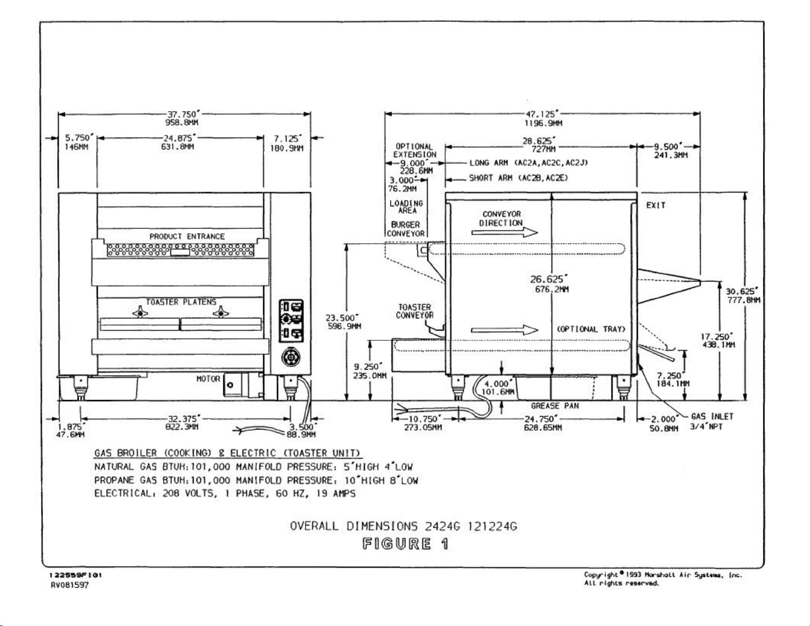
Overall Dimension.............................................................................................................................. Figure 1
Exploded View - Removable Parts.................................................................................................... Figure 2
Exploded View- Internal Parts .......................................................................................................... Figure 3
Exploded View - Drive System .......................................................................................................... Figure 4
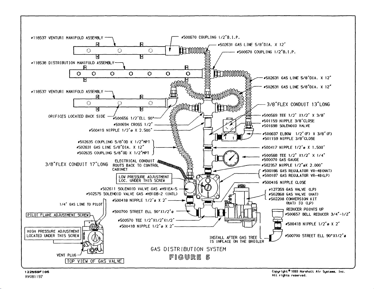
Gas Distribution System .................................................................................................................... Figure 5
Pilot System....................................................................................................................................... Figure 6
Conveyor - Axle Scraper.................................................................................................................... Figure 7
Restraining Device. ............................................................................................................................ Figure 8
Control Panel..................................................................................................................................... Figure 9
Burner Construction........................................................................................................................... Figure 10
Hot Surface Pilot Operation............................................................................................................... Figure 11
Hot Surface Pilot Trouble Shooting ................................................................................................... Figure 12
Autocat™ Catalytic Converter............................................................................................................ Figure 13
Autocat™ Catalytic Converter for LP Gas ......................................................................................... Figure 14
Lower Burner Support Assembly....................................................................................................... Figure 15
Conveyor Drive Shaft Assembly #132659......................................................................................... Figure 16
Kit, 9.5" Arm Extension Assembly..................................................................................................... Figure 17
Platen Assembly Left #124655.......................................................................................................... Figure 18
Platen Assembly Right #124656........................................................................................................ Figure 19
Conveyor Drive Shaft Assembly #124584......................................................................................... Figure 20
Toaster Loading Arm Assembly........................................................................................................ Figure 21
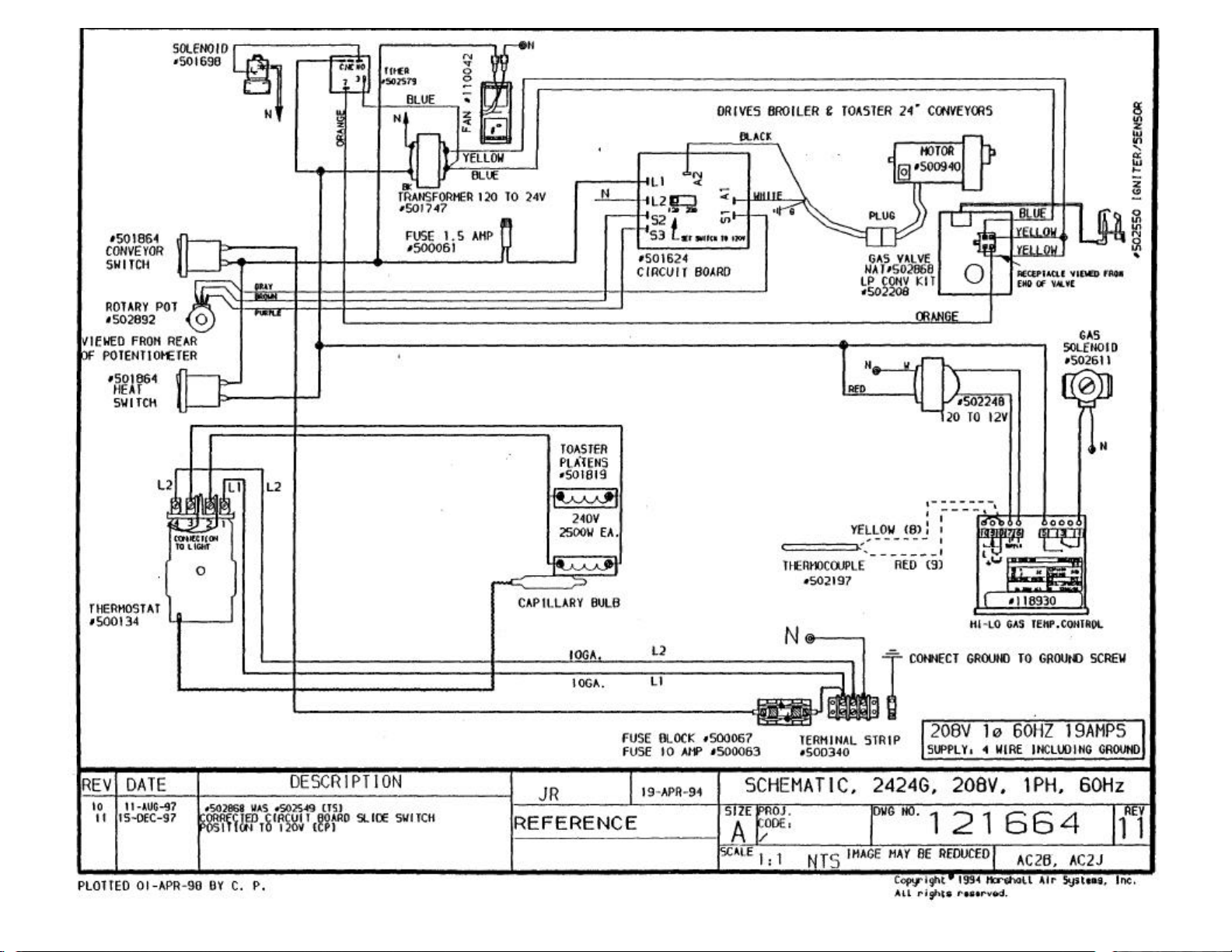
Wiring Schematic....................................... (208V, 1PH, 60Hz, 19 amps) Drawing #121664 (AC2B, AC2J)
Wiring Schematic....................................... (220V -240V, 1PH, 50Hz, 22 amps) Drawing #122597 (AC2BINTL)
Wiring Schematic....................................... (220V -240V, 1PH, 50Hz, 22 amps) Drawing #133551 (AC2B)
122559 RV052799
Copyright @ 1994 Marshall Air Systems, Inc. All
Rights Reserved.
Page 4

I. MACHINE SETTINGS
AUTOBROIL™
MODEL: 2424G
SERIAL NUMBER: __________________________________________________________________________
TYPE OF GAS: _____________________________________________________________________________
ELECTRICAL SUPPLY : _______________________________________________________________________
BROILER HIGH/LOW TEMPERATURE SETTING: _________________________________________________
GAS PRESSURE: HIGH ________________ LOW _____________
BROILER SPEED SELECT OR SETTING: __________________
TOASTER TEMPERATURE SETTING: _______________________________________________________
START-UP TECHNICIAN: ____________________________________________________________________
START-UP DATE: __________________________________________________________________________
COMMENTS: ______________________________________________________________________________
_________________________________________________________________________________
__________________________________________________________________________________
___________________________________________________________________________________
122559 RV020499
Copyright @ 1994 Marshall Air Systems, Inc.
All Rights Reserved.
2
Page 5

II. MACHINE INSTALLATION
PRE-INSTALLATION
1. After uncrating the Autobroil™ unit, inspect for shipping damage. Check that all control knobs are intact on the electrical
cabinet front. Contact the factory if there are obvious problems. Set the unit in place and leave the plastic wrapping on to
protect it from the debris and trash of building construction. DO NOT remove plug from gas inlet pipe. Leave this for the
Qualified Service Company. Check that machine has not been dented or damaged by the carrier. Notify your freight
carrier immediately to file a concealed damage claim, following the instructions attached to the outside of the shipping
crate. Your warranty will not cover freight damage.
2. Installation must be performed by a Qualified Service Company. The term "Qualified Service Company" means any
individual, firm, corporation or company which is either engaged in and is responsible for the installation or replacement
of gas piping on the outlet side of the meter, or the service regulator when a meter is not provided, or the connection,
installation or repair of gas appliances, who is experienced in such work, familiar with all precautions required, and has
complied with all the requirements of the authority having jurisdiction.
3. A remote gas shut -off valve must be provided and interlocked to the exhaust fire protection system.
A gas shut -off control is located on the top of the gas safety valve (behind the right side panel) for emergency
shut-off of gas supply to this appliance.
4. Because this unit is power fan exhausted, it is necessary to provide adequate make up air equal to the amount
removed. In addition to this, any other exhausts, flues, or air removal systems must be taken into consideration.
Examples of this are heat removal fans or hot water heater flues.
5. The appliance and its individual shutoff valve must be disconnected from the gas supply piping system during any
pressure testing of that system attest pressures in excess of 1/2 psig (3.45 kPa).
6. The appliance must be isolated from the gas supply piping system by closing its individual shutoff valve during any
pressure testing of the gas supply piping system at test pressures equal to or less than 1/2 psig (3.45 kPa).
APPLIANCE LOCATION
WARNING: IF NOT INSTALLED, OPERATED AND MAINTAINED IN ACCORDANCE WITH THE MANUFACTURER'S
INSTRUCTIONS, THIS PRODUCT COULD EXPOSE YOU TO SUBSTANCES IN FUEL OR FROM FUEL COMBUSTION
WHICH CAN CAUSE DEATH OR SERIOUS ILLNESS AND WHICH ARE KNOWN TO THE STATE OF CALIFORNIA TO
CAUSE CANCER, BIRTH DEFECTS OR OTHER REPRODUCTIVE HARM.
1. Position Autobroil™ to properly align with exhaust hood (refer to equipment plan).
2. The hood/ventilator for the appliance should be located in accordance with the National Fire Protection Association
Standard #96, "Removal of Smoke and Grease-Laden Vapors from Commercial Cooking Equipment" and any local
applicable requirements.
3
122559 RV020499
Copyright @ 1994 Marshall Air Systems, Inc.
All Rights Reserved.
Page 6

3. For proper installation, the minimum clearance from combustible construction is 0" from sides and 18" from
food loading end and food delivery end.
4. Adequate clearance should be maintained to allow easy access to loading and unloading areas of the
machine.
5. For servicing, unit must be moved two feet clear from all construction.
CAUTION: KEEP THE APPLIANCE AREA FREE AND CLEAR FROM COMBUSTIBLES.
ELECTRICAL INFORMATION
1. The domestic appliance is furnished with a cord only — no plug; and requires a 208 volt, A.C., 60 HZ, Single
Phase, 4 wire (including ground), 30 AMP circuit. Appliance must be electrically grounded in accordance with
local codes, or in the absence of local codes, with the National Electrical code ANSI/NFPA No. 70-latest
edition.
2. The international appliance requires 220 volt or 240 volt, A.C., 50 Hz, Single Phase and is furnished with a
cord only— no plug.
3. There is a Wiring Diagram located in the Owner's Manual and under the right side skin.
GAS PIPING TO APPLIANCE
1. Installation of this appliance must conform with local codes, or in the absence of local codes, with the
National Fuel Gas Code, ANSI Z-223.1 -latest edition.
2. In Canada, this appliance is to be installed in accordance with Standard CGA B149.1 or B149.2 Installation
Codes for gas burning appliances and equipment and any local applicable requirements.
3. The appliance is supplied with a 3/4" female pipe thread. The installer must make the pipe connection to the
unit in accordance with the "National Fuel Gas Code," ANSI Z-223.1-latest edition. The gas line connected to
the 3/4" female pipe thread cannot be less than a 3/4" pipe. The gas pressure and gas volume required by
this appliance is shown on Page 7. Gas piping from source to broiler must be adequate to satisfy these
requirements when all other gas appliances in the restaurant are operating at maximum demand.
4. A flexible AGA approved gas line is available. Instructions are (1) the installation shall be made with a
connector that complies with the Standard for Connectors for Movable Gas Appliances, ANSI Z21.699-latest
edition, and Addenda, Z21.69a-latest edition, and a quick-disconnect device that complies with the Standard
for Quick-Disconnect Devices for Use With Gas Fuel, ANSI Z21.41-latest edition, and Addenda, Z21.41alatest edition and Z21.41b-latest edition, and (2) adequate means must be provided to limit the movement of
the appliance without depending on the connector and the quick-disconnect device or its associated piping to
limit the appliance movement. See Figure 8 for details.
5. See Page 3, Items 5 and 6, for instructions on gas supply line pressure testing.
CAUTION: DO NOT OBSTRUCT THE FLOW OF COMBUSTION AND VENTILATION AIR.
122559 RV020499
Copyright @ 1994 Marshall Air Systems, Inc.
All Rights Reserved.
4
Page 7

PRE-OPERAT10N CHECK
Before lighting and operating your Autobroil™, make a quick check of critical items as follows:
1. Remove both side panels and check to see that all parts are in place and that none are damaged.
Particularly make sure all burners are in place and that the shields are in position on the bottom burners.
2. Start conveyor chains and check for proper operation. The conveyor chains should run free and not be
catching on anything.
3. The speed of the conveyor chains should be modulated from low to high, and back again without the chain
stopping.
4. Before first use, and after any special cleaning, it is necessary to "season" the broiler chain. This is done by
bringing the broiler to operating temperature and then (with burners still lit) applying liquid shortening from a
saturated cloth over the full width of the broiler chain while the chain makes 5 or 6 complete revolutions.
5. Check that gas pressure at appliance is correct (see Performance Criteria on Page 7).
6. Check that broiler grease tray is in place under burners (Figure 2).
LIGHTING INSTRUCTIONS FOR ELECTRONIC IGNITION SYSTEM
1. Turn exhaust system on. (Some hoods are so powerful that the broiler must be lit before the exhaust is
turned on).
2. Make sure filters are in place in the hood.
3. Turn conveyor chain on and set speed at approximate mid-point.
4. Remove right side cover. (Same Side As Controls)
5. Turn gas control switch on top of Honeywell gas safety valve to "ON".
6. Turn on the broiler heat switch on the control panel and verify all burners have ignited. Ignition is electronic
(does not require manual lighting of pilot). Set broiler temperature controller on right side of the broiler
(behind the side panel) to 400°F (204°C) (see Item 3 of setting temperature controller on Page 9).
7. If pilot flame or burners fail to light turn heat switch off and wait five minutes before attempting to relight.
SHUT-OFF INSTRUCTIONS
1. Turn heat switch off.
2. Wait 30 minutes.
3. Turn conveyor switch off.
4. Turn exhaust system off.
122559 RV020499
Copyright @ 1994 Marshall Air Systems, Inc. All
Rights Reserved.
5
Page 8

PERFORMANCE CRITERIA
1. The manifold pressure for each burner and appliance inlet pressure and gas amount is listed below:
TYPE OF GAS - Natural or Propane
PRESSURE AT THE APPLIANCE - 6.0-10.0 IWC for Natural
- 11.0-14.0 IWC for Propane
MANIFOLD PRESSURE - Low 4.0 IWC; High 5.0 IWC
for Natural
- Low 8.0 IWC; High 10.0 IWC
for Propane
- Low 9.0 IWC; High 10.0 IWC
for Propane ( LP Catalyst Only)
TOTAL GAS AMOUNT ** - 97,000 BTUH @ 100% High Fire
Manifold pressure is measured by a pressure gauge on the outlet side of the Honeywell gas valve. With the unit on for
at least twenty minutes and the broiler temperature controller set at 400°F (204EC) (see Item 3 on Page 9), the
pressure should be at 4.0 IWC (8.0 IWC for propane), (9.0 IWC for LP Catalyst). With the broiler temperature
controller set for 800°F (427°C) the high fire pressure is 5.0 IWC (10.0 IWC for propane). High pressure is adjusted
using the regulator in the top of the Honeywell gas safety valve. Low fire is adjusted using the gas pressure regulator.
See Figure 5 for gas system layout.
2. The burners in the appliance are a special infrared type. All of the air for combustion must be injected through the
Venturis. This makes orifice design and alignment very critical. The orifice design, in combination with the correct
natural or propane gas pressure will result in adequate air aspiration and mixing. There are no air shutters. No air
adjustment is needed. The proper orifice part numbers are found in Section VII - Replacement Parts.
CAUTION: DO NOT STACK BOXES OR IN ANY WAY BLOCK AREA IN IMMEDIATE VICINITY OF VENTURIS
OR IN ANY OTHER WAY OBSTRUCT FLOW OF COMBUSTION AIR.
2. Ignitor - sensor - pilot burner flame is adjustable with a small screwdriver. The cap screw behind the 1/4" gas line
exiting the valve should be removed. See Figure 5. The small adjusting screw is under the cap screw. Turning the small
adjusting screw inward (clockwise) will reduce the flame to the pilot. The pilot flame should be uniform and just large
enough to make a flame envelope around the end of the sensor and ignitor.
3. All burners will be bright orange when burning properly. If a dull red is observed after 30 minutes of warm-up with a blue
flame above the burner face, the orifice may be dirty or damaged. "Popping," or burning back at the orifice of the burner,
is a result of the burner screen being loose or a faulty gasket under the burner screen. LP machines may exhibit a light
"popping" sound when the unit is turned off; this is normal.
NOTE: IF BURNER SCREEN IS TORN OR HAS A HOLE, OR IF A GASKET IS LEAKING, THE BURNER
MUST BE REPAIRED. See Figure 10.
6
122559 RV020499
Copyright @ 1994 Marshall Air Systems, Inc.
All Rights Reserved.
Page 9

Ill. OPERATING INSTRUCTIONS
BROILER AND TOASTER ADJUSTMENT - DAILY
LIGHTING INSTRUCTIONS FOR ELECTRONIC IGNITION SYSTEM
1. Turn exhaust system on. (Some hoods are so powerful that the broiler must be lit before the exhaust is turned on.)
2. Make sure filters are in place in the hood.
3. Turn conveyor chain on and set speed at approximate mid-point.
4. Remove left side cover.
5. Turn gas control switch on top of Honeywell gas safety valve to "ON".
6. Turn on the broiler heat switch on the control panel and verify all of the burners have ignited. Ignition is electronic. Set
broiler temperature controller on right side of control cabinet to 400EF (204EC) (see Item 3 of setting temperature
controller on Page 9).
7. If pilot flame or burners fail to light turn heat switch off and wait five minutes before attempting to relight.
SHUT-OFF INSTRUCTIONS
1. Turn heat switch off.
2. Wait 30 minutes.
3. Turn conveyor switch off.
4. Turn exhaust system off.
TOASTER OPERATING INSTRUCTIONS
1. Turn the toaster temperature thermostat on the front of the control cabinet to between 425°F (218°C) and 450°F
(232°C).
2. Adjust the bun platens in height over the conveyor so the platen touches the bun as it is transported under the platen.
This produces a caramelized surface. If the platen is adjusted too low, the bun will be crushed.
TOASTER SHUT-OFF INSTRUCTIONS
1. Turn toaster thermostat to "OFF" position. (This can be done as soon as toaster buns are no longer needed.)
PROLONGED POWER FAILURE: NO ATTEMPT SHOULD BE MADE TO OPERATE THE APPLIANCE DURING
POWER FAILURE.
7
122559 RV020499
Copyright @ 1994 Marshall Air Systems, Inc.
All Rights Reserved.
Page 10

SETTING TEMPERATURE CONTROLLER FOR PROPER HIGH/LOW OPERATION - WEEKLY (This
Control Is Located Under The Right Broiler Side Cover)
1. Follow the procedure in Step 3 below in order to set temperature control for 400EF (204EC). After doing this,
turn on the burners.
2. Allow the broiler burners and conveyor chain to warm up for 60 minutes (with the chain at approximately the
correct speed).
3. Observe the temperature displayed: push "SET" and release to view the "SET POINT." To change set point
push "SET" and, within three (3) seconds, use the arrows to select a new set point. When setting the
High/Low for proper operation, make the set point THE SAME as the observed temperature made after the
sixty (60) minute warming. Broiler High/Low control is now set. The setting should be approximately 700°F
(371 °C). If not at least 650°F (343°C), the high and low gas pressures, as discussed on Page 7 under
Performance Criteria, may require adjustment or the hood exhaust may be excessive. The broiler will work
but will cook slower.
4. The temperature displayed by the control at all times is the ACTUAL temperature, except for a few
seconds after depressing SET.
5. Place one meat patty on the broiler chain. Bas ed on the appearance of the broiled patty, reset the Digital
Speed Control for the desired broiling quality. (Note: this single patty should be cooked to the maximum
degree of the Minimum/Maximum doneness tolerance.)
NOTE: THE NUMBERS DISPLAYED BY THE SPEED CONTROL ARE RELATIVE TO ONE
ANOTHER. THE LARGER THE NUMBER, THE FASTER THE CONVEYOR.
IV. SCHEDULED MAINTENANCE
DAILY CLEANING PROCEDURES
CAUTION: Do not touch the broiler section immediately after appliance shut -down. The temperature inside enclosures is in
excess of 500°F (260°C), which eliminates the need to clean any parts inside the enclosures for sanitary
purposes. Any grease that may build up on the exterior of the enclosures should be cleaned off with a damp
cloth and a minimum amount of detergent. Never use a large amount of water on the enclosure or allow
burner faces to get wet as this could cause premature burner or gasket failure. Disconnect the power
supply to the appliance before cleaning or servicing.
CAUTION: Under no circumstances should oven cleaner be used on this appliance. IT WILL EAT HOLES IN
THE ALUMINUM GAS VALVES AND GAS LINES, CAUSTIC FUMES CAUSE ELECTRICAL
COMPONENT DAMAGE, AND WILL CAUSE MANY OTHER PROBLEMS IF USED TO CLEAN THIS
BROILER.
CAUTION: KEEP THE APPLIANCE AREA FREE AND CLEAR FROM COMBUSTIBLES.
1. Allow broiler burners and chain to operate for 30 minutes after cooking last patty to burn off excess grease on broiler
components. Then turn the unit off and allow to cool. (This applies every time a meat chain is turned of f — regardless of
what time of day meat chain is shut down - and regardless of how few patties were broiled in the last 30 minutes, last
hour, etc.) This will clean some parts of the cooking chamber. Failure to perform this procedure daily will result in poor
cooking times.
8
122559 RV020499
Copyright @ 1994 Marshall Air Systems, Inc. All
Rights Reserved.
Page 11
2. Remove all exterior panels except those which are attached with screws. Be careful not to touch any hot
internal broiler components.
3. Remove burners from left side of unit and shake all debris off burners after they cool. Both top and bottom
burners may be slid out through the side of the machine. DO NOT WASH BURNER AS IT WILL DESTROY
GASKET. Brush surface of burner mesh with soft brush.
4. Remove lower burners and shields. Brush or scrape residue off shield.
WARNING: THE BURNER AND REVERBERATING SCREENS (LOCATED UNDER THE TOP BURNERS),
ARE MADE FROM INCONEL METAL MESH. THIS MATERIAL DETERIORATES WITH USE.
INSPECT THESE SCREENS DAILY AND REPLACE IF SCREEN IS SEVERELY CORRODED.
FAILURE TO DO SO CAN RESULT IN METAL PARTICLES BEING SERVED TO YOUR
CUSTOMERS.
5. Remove the following items and wash with hot soapy water.
* Toaster Exit Ramp Figure 2
* Broiler Grease Tray Figure 2
* Toaster Arm Cover Figure 2
* Crumb Tray (Toaster Section) Figure 2
* Grease Drain Channel Figure 3
* Catch Pan & Insert Figure 2
* Grease Pan Figure 2
* NOTE: these items may be removed during the 30 minute period.
Tunnel Guard Front & Rear Figure 2
Tunnel Closure Figure 2
Tunnel Fillers (2 each) Figure 2
Drip Tray (Broiler Arm) Figure 2
Lower Discharge Tent Figure 3
Meat Stripper Figure 3
6. With the conveyor switch ON and heat switch OFF, wire brush the broiler conveyor and, as it cools, wipe
with damp cloth.
7. Scrape deposits from the axles with the axle scraping tool, furnished with each machine as shown in Figure
*THIS IS IMPORTANT TO PREVENT GREASE FIRES AT REAR OF THE BROILER.
9
122559 RV020499
Copyright @ 1994 Marshall Air Systems, Inc.
All Rights Reserved.
Page 12

8. To Clean Toaster: Run a damp cloth down the conveyor (folded to the thickness of a bun) at least three times
a day and just before shutting down the unit for the night. Don't scrub the Teflon sheet with any coarse
materials.
9. Remove grease and meat residue from any part of remaining broiler structure where visible. Use a damp
cloth with detergent and a putty knife for best results.
10. After cleaning all removable parts as noted, allow to dry and reassemble.
MONTHLY CLEANING PROCEDURES
1. Turn off gas knob on top of the safety valve and disconnect electricity.
2. Remove upper burners, reverberating screens, lower burners, and shields to check for wear. These parts are
illustrated in Figure 3.
3. If the conveyor chain has been removed, make certain it is not on backward and CLOSE open links to
match other links. (Figure 7)
4. Using a damp cloth, wipe the inside of each burner venturi.
5. Reinstall burner screens, lower burner shields, and burners.
6. On LP Broilers with catalyst, install the (2) burner flame deflectors. (Figure 14)
7. Remove spark guard and wipe out. (Figure 2)
8. PROCEDURE FOR CLEANING OPTIONAL MARSHALL CHARBROILER CATALYSTS:
Marshall recommends that the restaurant soak the catalyst in a solution of commercial degreaser and
warm water for twenty minutes once a month. It is important to note that the catalyst may flake off the
metal honeycomb substrate if it is impacted by a high-pressure water stream. Therefore, we recommend
that the restaurant personnel first prepare the degreaser-and-water bath, and then place the catalyst in the
bath. We want to emphasize that the cleaning procedure involves a soak, rather than a scrubbing or hosing
procedure. After soaking for twenty minutes, rinse the catalyst either by soaking again in cold water or by
rinsing in a gentle stream of cold water. Following the rinse, shake the catalyst to remove all excess water,
and allow to dry at room temperature before returning it to service. A large fan may be used to move room
air more quickly over the catalyst to expedite the drying step. When installing catalyst on LP Broilers, be
sure broiler top extension is in place.
QUARTERLY CLEANING PROCEDURES & PREVENTIVE MAINTENANCE
1. If required, remove conveyor and soak in hot soapy water overnight. The chain is removed by lifting axle up
to produce slack and separating as described in Figure 7. When replacing chain, make certain the conveyor
is installed properly. PLACING CHAIN ON BACKWARD WILL CAUSE SEVERE BINDING PROBLEMS.
CLOSE open links to match other links. (Figure 7)
2. If required, spread conveyor links open with screwdriver or chain pliers (part #500033). Lift front axle up to
make slack in the conveyor belt, unhook conveyor chain and remove to gain access to lower cooking
chamber for cleaning side walls. Make reference to the orientation of the conveyor links and the conveyor
direction for reassembly. (Figure 7)
3. Lubricate the roller (drive) chain with a few drops of any grade motor or machine oil.
10
122559 RV020499
Copyright @ 1994 Marshall Air Systems, Inc.
All Rights Reserved.
Page 13

4. Remove and inspect all motor brushes and replace if less than 1/4" is left.
5. Do not remove internal gas lines for cleaning.
6. Clean gas orifices:
• Orifices are passageways directing gas flow into burner. Uneven gas flow or air to
gas ratio is caused by dirty or damaged orifices.
• Orifices are made of brass. Use special care in cleaning-don't gouge or make gas
holes bigger.
• To reach orifices, remove burners.
• Use a pipe cleaner dipped in rubbing alcohol to clean orifices. Swab until clean;
free of carbon build-up. Do not use drill bit; this will damage the orifices.
7. Blow out all six (6) burners through the venturi opening with a low pressure air source.
CAUTION: Do not drop burners or get wet as this may break gasket or add to
premature burner failure.
8. INVENTORY THE SPARE PARTS KIT AND ORDER MISSING PARTS AS NEEDED. KEEP A
COMPLETE SET OF PARTS ON HAND AT ALL TIMES.
V. TROUBLESHOOTING
This section contains a list of possible problems with the Autobroil™ unit. ALL ELECTRICAL TROUBLE SHOOTING
INVOLVING ACCESS INTO THE MOTORS OR ELECTRICAL ENCLOSURES MUST BE PERFORMED BY A QUALIFIED
ELECTRICIAN. All items marked with asterisks (*) should be performed by service agency qualified to perform
service on gas fired appliances.
1. PROBLEM: BURNER BACKFIRES. Flashback, blue flame at entrance to burner makes motor-boating sound like a
blowtorch. IMPORTANT: If burner backfires, turn it off. Continued operation will cause damage to the entire burner.
POSSIBLE CAUSE:
* A) Burner screen failure (hole) or burner gasket. SOLUTION: Replace burner screen or gasket.
* B) Burner over-fired - manifold pressure too high. SOLUTION: Check and reset gas control
regulator to give rating plate value for manifold pressure (shown under Performance Criteria on Page 7). Wait
5 minutes & relight. Flashback will not occur immediately unless a large opening in or around the burner
screen is evident. Wait an hour after relighting to check that problem is solved. Figure 5 illustrates which
regulator sets high and low gas pressures.
* C) Check to ensure all screws holding the burner screen in place are snug. See Figure 10.
2. PROBLEM: FLAMES VISIBLE AT EXHAUST STACK OR IN CHAMBER.
POSSIBLE CAUSE:
* A) Low gas pressure. SOLUTION: Check and reset gas control regulator to give rating value for manifold
pressure (shown under Performance Criteria on Page 7). Figure 5 illustrates which regulator sets high and
low pressures.
122559 RV020499
Copyright @ 1994 Marshall Air Systems, Inc. All
Rights Reserved.
11
Page 14

3. PROBLEM: PILOT FLAME GOES OUT (STUDY FIGURE 11 & 12 FOR PILOT OPERATION).
POSSIBLE CAUSE:
* A) Pilot assembly dirty or bent. SOLUTION: Check for bent pilot gas line and/or dislodge debris
* B) Low gas pressure. SOLUTION: Increase gas pressure to appliance (see Figure 5).
* C) Pilot orifice clogged. SOLUTION: Dislodge debris or replace orifice.
* D) Wires from pilot assembly loose. SOLUTION: Trace wires to where they plug into gas valve and check
connection. (Figure 6)
* INSTRUCTIONS MARKED WITH ASTERISKS SHOULD BE PERFORMED BY AUTHORIZED SERVICE PERSONNEL.
4. PROBLEM: BURNER WILL NOT LIGHT AT ALL.
POSSIBLE CAUSE:
A) Hot Surface Ignition. SOLUTION: Recycle heat switch. See Figure 11 and 12.
B) Orifice. SOLUTION: Check that orifice is not plugged. (If it is necessary to change the orifices, new ones must
be ordered from the factory).
C) Check that flame runner is fully lit (Figure 6). SOLUTION: If not, clean flame runner orifice or remove and
clean flame runner.
D) Pilot. SOLUTION: Pilot must light and stay lit in order for burner to light. Check pilot problem list (see Item 3
on Page 13).
* E) Gas Solenoid. SOLUTION: Check that solenoid valve on main gas valve is working.
F) Pilot Solenoid. SOLUTION: Check that solenoid valve #501698 on Figure 5 is functioning. It
opens for 120 seconds during the ignition cycle and then closes with a delay -on-break timer in the control
cabinet.
G) Pilot Jumpers. SOLUTION: Check the short and long pilots shown at the top of Figure 6 to make certain they
are not plugged. They turn off after 120 seconds from activating heat switch.
5. PROBLEM: CONVEYOR CHAIN WILL NOT MOVE.
POSSIBLE CAUSE:
* A) Check for object caught in conveyor, causing a jam. SOLUTION: Remove object.
* B) Check 1.5 amp fuse on top of the control cabinet (Figure 6) SOLUTION: Replace if blown and recycle
ON/OFF switch.
* C) Check 10 amp fuse. SOLUTION: Replace if blown.
* D) Check to see if motor shaft is moving. SOLUTION: Sprocket needs to be tightened.
* E) Check switch to make sure power is flowing through it. SOLUTION: Replace switch.
12
122559 RV020499
Copyright @ 1994 Marshall Air Systems, Inc. All
Rights Reserved.
Page 15

* F) Connect motor control leads to an operating motor speed control board. SOLUTION: If motor runs, replace
motor control board. If motor still does not run, replace motor.
6. PROBLEM: CONVEYOR RUNS BUT SPEED IS CONSTANT
POSSIBLE CAUSE:
* A) There are four parts to the motor system. They are the motor, the circuit board, the digital speed control and
the fuse mounted on the top of the control cabinet. The most likely problem would be a blown fuse.
SOLUTION: Using spare parts, replace one part at a time until the trouble spot is identified.
* INSTRUCTIONS MARKED WITH ASTERISKS SHOULD BE PERFORMED BY AUTHORIZED SERVICE
PERSONNEL.
7. PROBLEM: REPEATED MECHANICAL BINDING.
POSSIBLE CAUSE:
A) Check to see that chain is not on backward. SOLUTION: See proper chain installation on Figure 7.
B) Inspect chain closely for bent or warped links that may be snagging and causing a binding
condition. Also check that the chain links are not climbing out of the sprockets as the conveyor rotates.
SOLUTION: Straighten or replace bad links.
C) Make sure the axle assembly is clean and free of grease and food residue to allow smooth movement of
the conveyor. SOLUTION: Clean axle. See Figure 7.
D) Check the axle assembly to make certain all set collars, bearings, etc. are properly positioned and secure.
E) Disassemble conveyor axle assembly and check condition of bushings and bearings for excessive wear.
SOLUTION: Replace if worn or damaged.
F) Visually inspect the motor drive chain assembly for smooth rotation of chain. SOLUTION: Make certain there
are no binding or worn components.
G) Make sure conveyor is not catching on meat stripper. SOLUTION: Straighten bent stripper.
8. PROBLEM: HIGH/LOW CONTROL DOES NOT WORK.
POSSIBLE CAUSE:
* A) Determine gas pressure by checking gas pressure gauge. SOLUTION: Adjust per instructions on Page 7.
B) If unit stays in high or low, check that control is properly set for about 700°F (371 °C). SOLUTION:
Res et to proper temperature as shown in Item 3 on Page 9.
B) If control flashes "EEE" or "999", then inspect thermocouple for continuity. SOLUTION: Check to be sure
thermocouple leads are securely fastened to temperature controller. If so, then replace thermocouple.
13
122559 RV020499
Copyright @ 1994 Marshall Air Systems, Inc.
All Rights Reserved.
Page 16

* INSTRUCTIONS MARKED WITH ASTERISKS SHOULD BE PERFORMED BY AUTHORIZED SERVICE
PERSONNEL.
9. PROBLEM: HAMBURGERS WILL NOT FALL CORRECTLY.
POSSIBLE CAUSE:
A) Meat stripper is dirty or adjusted too far from conveyor. SOLUTION: Clean and reposition near chain by moving
brackets that hold stripper. See illustration on Figure 3.
10. BUNS WILL NOT GET HOT ENOUGH.
POSSIBLE CAUSE:
A) Check that toaster touches bun. SOLUTION: Lower platens to correct height to compress buns properly for
toasting.
B) Check toaster electrical power. SOLUTION: Turn thermostat ON.
C) Check speed to make sure conveyor is not running too fast. SOLUTION: Speed should be about 50 to 60
seconds.
* D) Check element connections on top of platens. SOLUTION: Tighten
E) Using a surface thermometer on top of platen, check that thermostat is functioning. SOLUTION:
Replace thermostat as appropriate.
F) Check bulb on the end of the thermostat capillary tube to make sure it is inserted into side of platen.
SOLUTION: Remove control cabinet lid and push bulb into position.
G) Inspect the thermo stat capillary tube for breaks or kinks. SOLUTION: Replace the thermostat.
11. BUNS WILL NOT FEED CORRECTLY.
POSSIBLE CAUSE:
A) Check for buildup of black residue on teflon sheet caused by improper cleaning. SOLUTION:
See cleaning instructions under Daily Cleaning Procedure.
B) Teflon sheet is worn or damaged. SOLUTION: SHEET MUST BE REPLACED.
** INSTRUCTIONS MARKED WITH ASTERISKS SHOULD BE PERFORMED BY A QUALIFIED SERVICE
COMPANY.
VI. ASSEMBLY & DISASSEMBLY INSTRUCTIONS
1. The burner screen (Figure 10) may be replaced by removing all the screws from the burner housing and frame. The
assembly will then lift off. Remove all old gasketing and replace. Compress the new assembly into the burner housing
with hand pressure all around the outside of the burner housing. Insert new screws and snug the screws in a
staggered sequence. Do not over tighten screws. These screws will keep the frame tight against the gasket.
14
122559 RV020499
Copyright@ 1994 Marshall Air Systems, Inc.
All Rights Reserved.
Page 17

2. The restraining device is a separate line and should be anchored no less than 6" away from the gas
connector and in a parallel position to the flexible line. The following instructions refer to Figure 8. By
using the adjusting clips (1) alter the length of the cable (2) so that the overall length (3) is 3" to 6" shorter
than the length of the flexible gas line including the fitting. Then attach staple (4) to an existing wall or
other structurally sound surface. Attach scissor hook (5) to staple and secure with cotter pin. Finally
attach spring hook (6) to gas appliance as shown in Figure 8. Make certain that the overall length of the
restraining line is shorter than the gas line so no strain is placed on the gas line or piping when moving
the unit.
3. When replacing the thermocouple which attaches to the hi/low temperature controller, make certain it is
inserted through side wall of machine into cooking chamber exactly one inch (1").
4. To remove and clean lower burner shields - remove left side skin and lower burner end cover (Figure 3),
slide burners out thru opening and lift off shields from burner pins. Scrape and wire brush shields.
5. To properly set the clearance between the meat stripper and the conveyor chain, the machine must be
HOT. Loosen the bolts holding the brackets to the sides of the unit and adjust their position until the top
edge of the stripper is within 1/16" of the hot conveyor. See Figure 3.
WARNING: THIS APPLIANCE IS NOT CAPABLE OF BEING SAFELY PLACED INTO OPERATION DURING
A POWER FAILURE AND NO ATTEMPT TO OPERATE IT SHOULD BE MADE.
VII. REPLACEMENT PARTS - 2424G
When ordering parts, make sure to specify the machine model number, type of gas and serial number as
shown by the label attached to the right side cover.
PART# DESCRIPTION FIGURE
100367 Scraper Axle 7
101357 Bearing, Teflon .750" 4
109285 Mount Teflon Cloth 4
110042 Fan 6,Schematic
115665 Burner, 24" 10
115816 Top Burner End Cover 3
115847 Toaster Idler Assembly 3
115856 Screen Mounting Clip 3
115857 Reverberating Screen 3
116084 Conveyor Support Tube 3
15
122559 RV020499
Copyright @ 1994 Marshall Air Systems, Inc.
All Rights Reserved.
Page 18

116088 Conveyor Shaft (Toaster Idler) 3
116126 Thermocouple Fitting 4
117213 Lower Burner End Cover 3
117234 Motor Mounting Plate 4
117244 Meat Stripper 3
117300 Kit, Conveyor Arms (Short Arms Only) 4
118041 Grease Drain Channel 3
118401 Broiler Grease Tray 2
118402 Catch Pan Insert (AC2B) 2
118425 Spark Guard 2
118426 Motor Sprocket Guard 4
118499 Catch Pan 2
118529 Conveyor Arm Support 3
118532 Tunnel Closure 2
118537 Venturi Manifold Assembly 5
118538 Distribution Manifold Assembly 5
118548 Drip Tray (Broiler Arms) 2
118701 Front Tunnel Guard (AC2B) ' 2
118702 Rear Tunnel Guard (AC2B) 2
118703 Crumb Tray (Toaster) 2
118709 Burner Shield 3
118930 Temperature Control (High/Low Gas) Schematic
119521 Lighter Arm Assembly 6
122268 Spare Parts Kit (AC2B, AC2J) N/A
119530 Meat Stripper Hanger (Right) 3
119531 Meat Stripper Hanger (Left) 3
119538 Tunnel Filler 2
119539 Lower Discharge Tent 3
120029 Support Pin 4
122559 RV020499
Copyright @ 1994 Marshall Air Systems, Inc.
All Rights Reserved.
16
Page 19

120030 Conveyor Idler Shaft (Short Arms) 3
120048 Wiper Blade 3
120113 Guard, Front Tunnel (AC2J) 2
120114 Guard, Rear Tunnel (AC2J) 2
120811 Toaster Ramp (AC2B) 2
121658 Toaster Arm Cover (LH) 2
121696 Conveyor Wiper Assembly 3
122551 Broiler Idler 3
122559 Owner's Manual N/A
123145 Gasket, Burner 10
123832 Heat Guard 2
123844 Drive Axle (Toaster) 4
123865 Burner Track, Open End 3
123866 Burner Track, Stop End 3
123867 Burner Track, Rails 3
123879 Catch Pan 2
124578 Broiler .500" Bearing Asby (Short Arms) 3
124580 Sprocket Idler Asby 4
124584 Conveyor Drive Shaft Assembly 20
124596 Burner Track Rail (Short) 3
124630 Burner Screen Kit 10
124643 Sprocket #3512 x .750" (AC2J) 4
124651 Burner Screen Assembly 10
124652 Burner Housing 10
124655 Platen Asby Left 18
124656 Platen Asby Right 19
124657 Burner Shield Mounting Kit 10
124662 Catch Pan Assembly 2
124675 Kit, Broiler Arm Extension 9.5" (AC2J) 17
122559 RV020499
Copyright @ 1994 Marshall Air Systems, Inc. All
Rights Reserved.
17
Page 20

124685 Cover Assembly Arm Extension 9.5" (AC2J) 17
124724 24" Conveyor Cut Link (Per Link) 7
125702 Extended Arm Catalyst Cover 13(Not Shown)
127027 Toaster Arm Cover (RH) 2
127359 Gas valve, LP 5
130657 Kit, Motor Reversing N/A
131452 Lower Burner Support Assembly 15
131396 Side Panel Assembly 2
132659 Conveyor Drive Shaft Assembly (AC2J) 16
132910 Catch Pan, Insert (AC2J) 2
132922 Meat Stripper (AC2J) 3
132941 Teflon Sheet 12" x 31" (AC2J) 4
133558 Exit Tray Bun Ramp (AC2J) 2
500027 24" Conveyor Belt SS (Per Foot) 62" (3"arms), 82" (9"arms) 7
500033 Pliers Chain Conveyor 7
500035 Chain Roller #35 (Per Link) 4
500037 Sprocket #3518 X .500" (Motor) 4
500040 Sprocket #3510 x .500 (AC2J) 4
500061 Fuse 1.5 amp 6,Schematic
500063 Fuse 10 Amp Schematic
500067 Fuse Block Schematic
500070 Gas Gauge 5
500083 Link Half (Drive Chain) 4
500092 Link Master (Drive Chain) 4
500112
Potentiometer - Digital (Used on Broilers with serial numbers before
10941733
Schematic
500118 Set Collar 3/4" 3,4
500134 Toaster Thermostat Schematic
500158 Cord 10/4-SJO (8 Foot) 6
500174 Gas Line Flex 36" With Restraint 8
122559 RV020499
Copyright @ 1994 Marshall Air Systems, Inc. All
Rights Reserved.
18
Page 21

500186 Gas Regulator VR-48 (Natural) 5
500187 Gas Regulator VR-48 (LP) 5
500336 Gas Line Restraining Device RD-36 8
500340 Terminal Strip 3 Pole Schematic
500417 Nipple 1/2" x 1.500" 5
500419 Nipple 1/2" x 2.500" 5
500657 Bell Reducer 3/4"-1/2" 5
500811 Tool Box N/A
500940 Drive Motor 4
500941 Motor Brushes for Motor ASPEC 29894G@ N/A
501154 Teflon Sheet 12" x 35" (AC2B) 4
501163 ELL 90E 5
501624 Circuit Board MM23011 C SPEC #185B Schematic
501698 Solenoid Valve 120 Volt Coil (Pilots) 5
501747 Transformer 120V -24V Schematic
501748 Thumb Screw 4,6
501819 Toaster Platen 2500W 240V 4
501827 Knob With Stud 4
501835 Grease Pan 2
501864 Switch Schematic
502197 Thermocouple Type K (Broiler Tunnel) 4
502248 Transformer 120V -12V Schematic
502395 Sprocket #501 Ox 3/4" 4
502450 Pilot, Long 2.250" Long 6
502451 Pilot, Short 1.500" Long 6
502538 Bearing, Red 3
502550 Ignitor -Sensor- Pilot 6
502579 Timer 120 Sec. Delay Brake Schematic
502611 Solenoid Valve 120 Volt Coil (High-Low Pressure) 5,Schematic
122559 RV020499
Copyright @ 1994 Marshall Air Systems, Inc. All
Rights Reserved.
19
Page 22

502631 Pipe Corrugated X 12" (5/8" DIA.) 5
502646 Screws, 8-32 x 1.250" (M) Pan 10
502647 Kep Nut, 8-32 10
502838 Sprocket #3515 X .750" (Toaster Drive) 4
502839 Sprocket #3524 X .750" (Broiler Drive) (AC2B, AC2J) 4
502868 Gas Valve (Natural) 5, Schematic
502892
Potentiometer - Rotary (used on broilers with Serial Numbers 10941733
and higher)
9,Schematic
502906 Potentiometer Knob 9
502989 Spacer 10
502991 Screws, 8-32 x .500 Flat Head 10
503081 Potentiometer Knob Lock 9
503287 Brush Motor for Mot or AType 24Y2FETM-D4" N/A
NATURAL GAS ORIFICES
121668 Long & Short Pilot Orifice #68 6
502915 Orifice #BCR 18X (Ignitor-Sensor- Pilot Burner) 6
501718 Orifice #70 (Lighter Arm) 6
502713 Orifice #49 Button (Burners) 6
502765 Orifice #47 Button (Burners) (AC2J) 6
LP GAS ORIFICES
122640 Long & Short Pilot Orifice .018" (Upper) 6
500487 Long & Short Pilot Orifice .011" (Lower) 6
502924 Orifice .010" (Ignitor-Sensor Pilot Burner) 6
502766 Orifice #79 (Lighter Arm) 6
502863 Orifice #56 Button ( Burners) 6
INTERNATIONAL PARTS (50 Hz)
122615 Temperature Control (High/Low Gas) Schematic
502168 Transformer 240V to 12V, 6VA Schematic
502409 Transformer 240V to 120V, 30 VA Schematic
502575 Gas Solenoid Schematic
20
122559 RV020499
Copyright @ 1994 Marshall Air Systems, Inc. All
Rights Reserved.
Page 23

502868 Gas Valve Schematic
502916 Transformer 240V to 24V, 56VA Schematic
503149 Orifice, Burner #59, Button for LP/Butane Gas Broilers Figure 6
OPTIONAL CATALYTIC CONVERTER
123734 Broiler Arms Drip Tray 13
123735 Broiler Arm Rear Cover 13
123832 Heat Guard 13
125690 "V" Baffle Insert, Mount Asby 13
502944 Catalyst 13
OPTIONAL CATALYTIC BROILER USING LP GAS
131093 Burner Flame Deflector 14
131094 Catalyst Extension Asby 14
131365 ASPL@ Top Burners 14
122559 RV020499
Copyright@1994 Marshall Air Systems, Inc.
All Rights Reserved.
21
Page 24

BROILER LIMITED WARRANTY
RV121096
LI
MITED. BRL.DOC
MARSHALL AIR SYSTEMS, INC., ("Marshall") warrants to the first purchaser ("Purchaser") all new equipment of its
manufacture to be free of defects in material and factory workmanship for a period of one year* from date of shipment provided that (i) the
equipment is installed in the Continental United States, Canada or Hawaii and operated according to the Owner's Manual while located at
the original address of installation, (ii) the warranty registration card has been completed and returned to the factory within fifteen (15)
days after installation, and (iii) a post-installation start-up has been performed by an authorized service representative (portable
equipment not applicable). Marshall's obligation under this warranty is limited to the repair or replacement at its option of any defective
part. Under certain circumstances, Marshall will reimburse Purchaser for limited labor costs in replacing parts during a period of not more
than ninety (90) days after date of shipment, provided that Labor Reimbursement instructions are followed and items i, ii, and iii above are
completed. See special provision for portable equipment. It is understood that Marshall's obligation with respect to equipment located
outside the Continental United States, Canada or Hawaii is limited to replacement parts only.
Marshall, this warranty DOES NOT COVER:
(hosing or "watering down" equipment will cause electrical failures not covered by warranty);
as a result of improper installation, misuse, abuse, alteration of original design, incorrect voltage, unauthorized service, breakage of
fragile items, or any other damage caused by an act out of Marshall's control.
warranty does not cover cooking performance, smoke capture or holding temperatures which is a function of food types, textures,
temperatures, equipment line ups and other variables chosen by the Purchaser and over which Marshall has no control. This warranty
does not apply to damage caused by accident or to damage caused by the negligence of Purchaser or the employees of Purchaser or to
damage caused by lightning generated electrical current or any other Act of God whatsoever. This warranty does not apply to any
equipment bearing a serial number which has been tampered with or altered. Marshall reserves the right to accept or reject any such
claim in whole or in part. Marshall will not accept the return of any product without prior written approval from Marshall, and all such
approved returns shall be made at Purchaser's sole expense.
WARRANTY OF MERCHANTABILITY AND THE IMPLIED WARRANTY OF FITNESS FOR A PARTICULAR PURPOSE, OR PATENT
OR OTHER INTELLECTUAL PROPERTY RIGHT INFRINGEMENT, AND EXCEPT FOR THE EXPRESS WARRANTY CONTAINED
HEREIN, THE EQUIPMENT IS SOLD "AS IS." REMEDIES UNDER THIS WARRANTY AND UNDER ANY WARRANTY THAT MAY
SURVIVE THE DISCLAIMER OF WARRANTIES ARE LIMITED EXCLUSIVELY TO THOSE REMEDIES DESCRIBED ABOVE. NO
OTHER REMEDY IS AVAILABLE UNDER THIS WARRANTY OR ANY OTHER WARRANTY. NEITHER THIS WARRANTY NOR ANY
OTHER WARRANTY COVERS, AND MARSHALL WILL NOT BE RESPONSIBLE FOR, ANY INCIDENTAL OR CONSEQUENTIAL
DAMAGES, INCLUDING BUT NOT LIMITED TO THE COST OF DISASSEMBLY AND SHIPMENT OF THE EQUIPMENT,
PRODUCTION OR PRODUCT LOSSES, INJURY TO OTHER PROPERTY, OR LOST PROFITS RESULTING FROM THE USE OF OR
INABILITY TO USE THE PRODUCTS OR FROM THE PRODUCTS BEING INCORPORATED IN OR BECOMING A COMPONENT OF
ANY OTHER PRODUCT OR GOODS, OR OTHER LOSSES. WHERE, DUE TO OPERATION OF LAW, CONSEQUENTIAL AND
INCIDENTAL DAMAGES CANNOT BE EXCLUDED, THEY ARE EXPRESSLY LIMITED IN AMOUNT TO THE PURCHASE PRICE OF
THE EQUIPMENT.
*The following broiler parts have a six month part warranty:
• Burner Shields and Screens Burner Grids
• Burner Gaskets
• Electric Broiler Elements
• Flame Runners
Because Marshall does not and cannot control Purchaser's installation, use, and maintenance of equipment manufactured by
Any equipment calibration;
Any component disassembled in the field;
Damage due to improper cleaning and/or abuse, i.e. burner rotation, grease accumulation in electrical components or plugs
Blown fuses or bulbs, motor brushes and Teflon components;
Any replacement parts used on the equipment which are not purchased from Marshall;
Accessory components not installed or manufactured by Marshall.
Shipping damage must be reported to the carrier and is not covered under this warranty. Marshall will not be liable for damage
The effect of corrosion, fire, and normal wear on the equipment or component parts is not covered by this warranty. This
THIS WARRANTY IS IN LIEU OF ALL OTHER WARRANTIES, EXPRESS OR IMPLIED, INCLUDING THE IMPLIED
FOR INTERNATIONAL INSTALLATIONS -- PLEASE CONTACT YOUR LOCAL
MARSHALL AIR SYSTEMS RECOGNIZED DISTRIBUTOR.
Copyright © 1994 Marshal Air Systems, Inc.
All Rights Reserved
Page 25

PROCEDURE .BRL. DOC
BROILER WARRANTY PROCEDURES
RETURN GOODS AUTHORIZATION FOR PARTS - FACTORY DIRECT
For prompt warranty parts replacement and RGA processing, please call Marshall's Customer Service
Department at 800-722-3474 or 704-525-6230 for assistance. In all cases, a Return Goods
Authorization (RGA) number must be issued by Marshall Air Systems, Inc. Unauthorized returns will
not be processed.
Option #1: Purchaser to return part prepaid to Factory, Marshall to repair or replace at own
expense if defective, and ship part back to Purchaser prepaid.
Option #2: Marshall to furnish replacement part freight prepaid with or without requesting return of
the defective part.
WARRANTY LABOR REIMBURSEMENT AND/OR PARTS REPLACEMENT THROUGH
RECOGNIZED MAINTENANCE & REPAIR CENTERS
Normally, labor will be covered under the start up fee. In the unlikely event this does not apply, consult Marshall
Air Systems, Inc. To be reimbursed for warranty labor costs, authorization must be given by Marshall Air
Systems, Inc. Unauthorized work will not be reimbursed. Work must be performed by a Marshall Air Systems
Recognized Service Agency within the service time allowance guidelines and must be submitted along with failed
parts (if applicable) to Marshall Air Systems (freight prepaid) within 30 days of the work being performed. Travel
is covered, but must not exceed 50 miles or 1 hour, whichever is greater. Call Marshall's Service Department at
800-722-3474 or 704-525-6230 with any questions. Service is to be performed by recognized service agencies
during normal working hours. Owner to pay for all other charges including excessive travel or overtime charges.
DIAGNOSTIC LABOR CHARGES ARE INCLUDED IN SERVICE TIME ALLOWANCE GUIDELINES. All
portable equipment (under 90 pounds) shall be delivered by Purchaser, at his/her expense, to the nearest
authorized service agency for in-shop repair or at purchaser's discretion he/she will pay all travel time and
mileage expenses for portable equipment.
NON-WARRANTY RETURNS:
All items returned for customer convenienc e are subject to a 20% restocking fee. In the event of an error by
Marshall Air Systems, Inc., a Returned Goods Authorization will be issued for full credit.
FOR INTERNATIONAL INSTALLATIONS " PLEASE CONTACT YOUR
LOCAL MARSHALL AIR SYSTEMS RECOGNIZED DISTRIBUTOR.
124727 RV042798
Copyright® 1994 Marshall Air Systems. Inc.
All Rights Reserved
Page 26
Page 27

Page 28

Page 29

Page 30
Page 31

Page 32

Page 33

Page 34

Page 35

Page 36

Page 37

Page 38

Page 39

Page 40

Page 41

Page 42

Page 43

Page 44

Page 45

Page 46

Page 47
Page 48

Page 49

Page 50

 Loading...