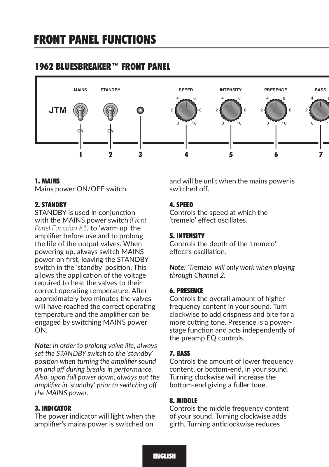
How it Works
Log In / Sign Up
Buy Points
How it Works
FAQ
Contact Us
Questions and Suggestions
Users
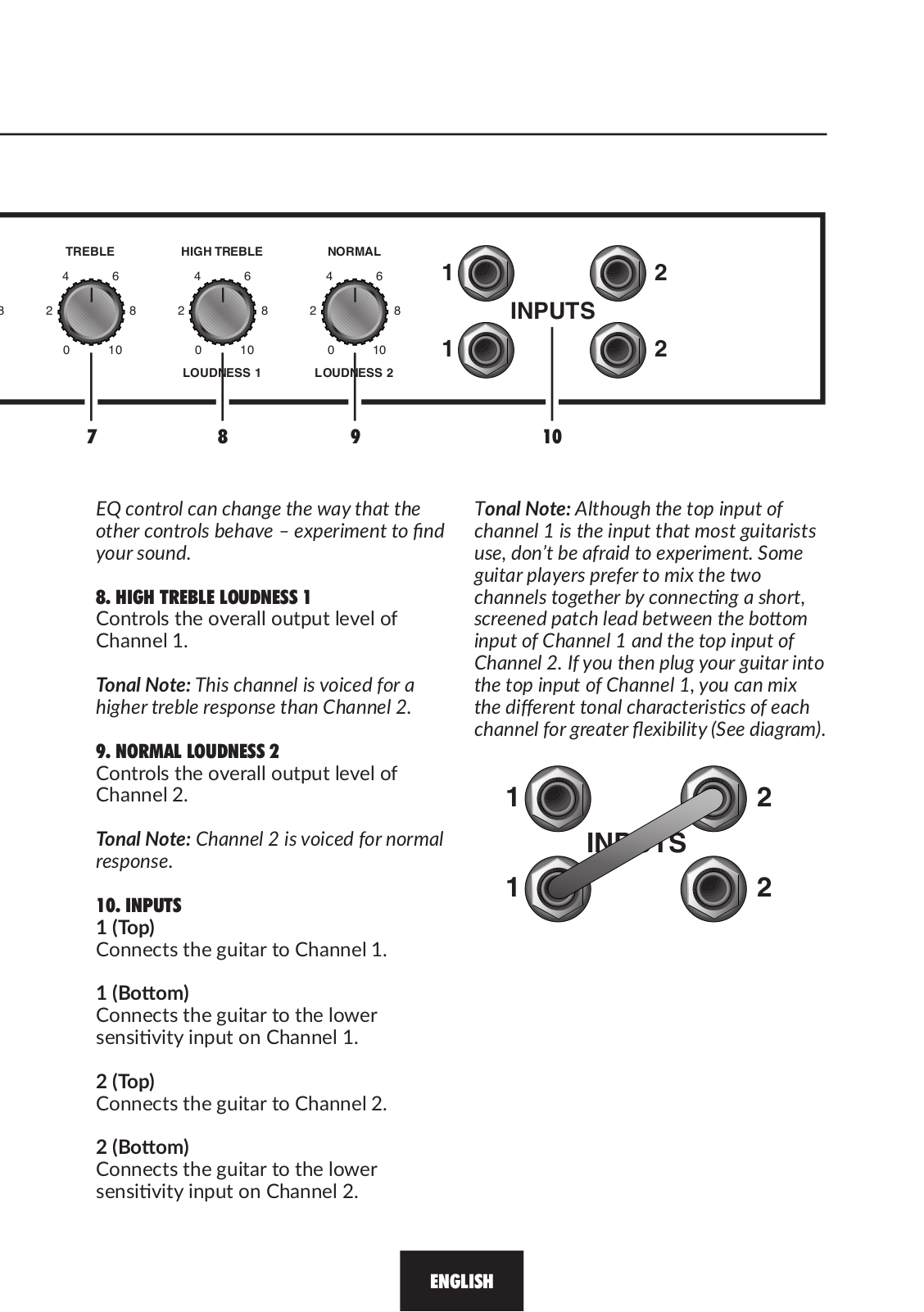
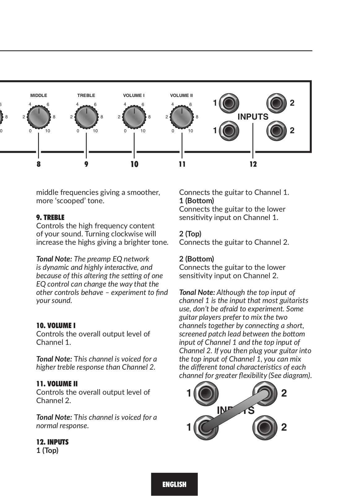
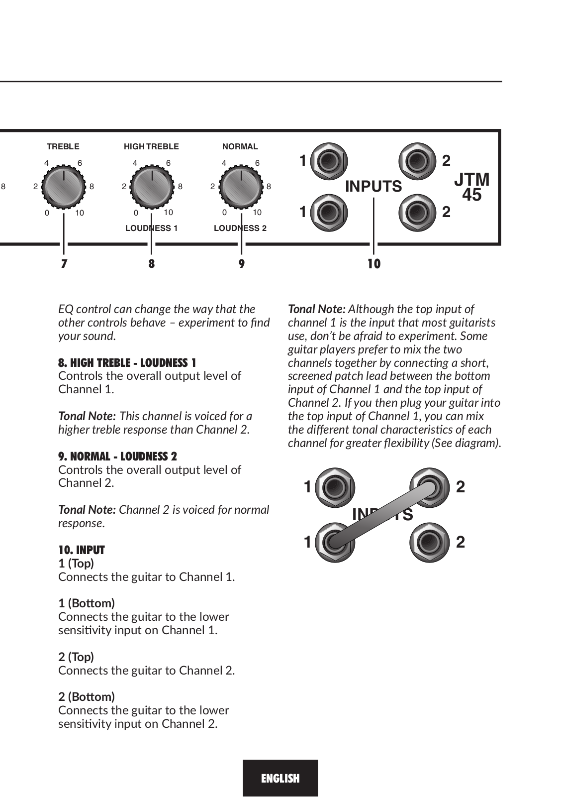
Marshall
Loading...
D
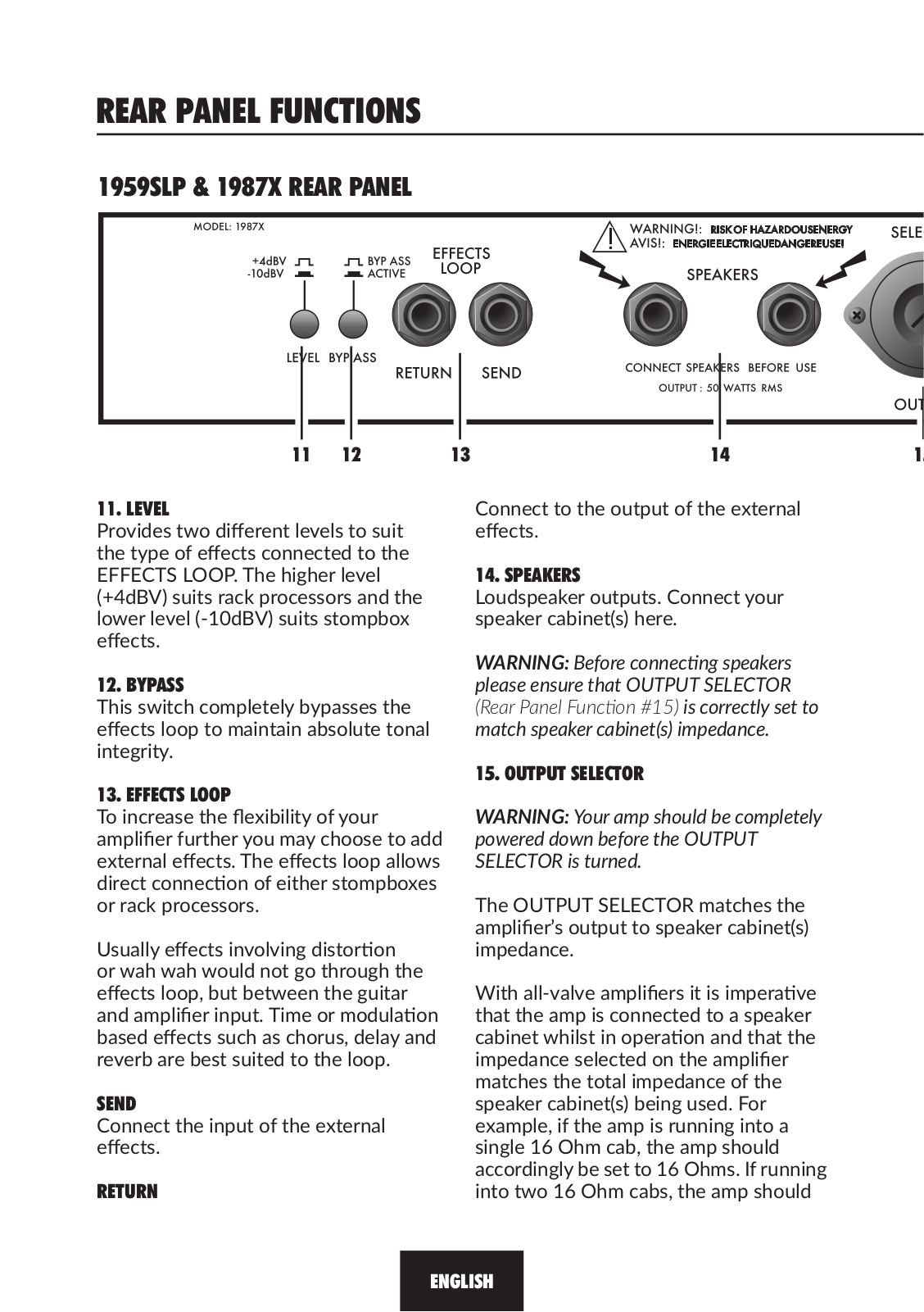
DSL15C
DSL15H
DSL1CR
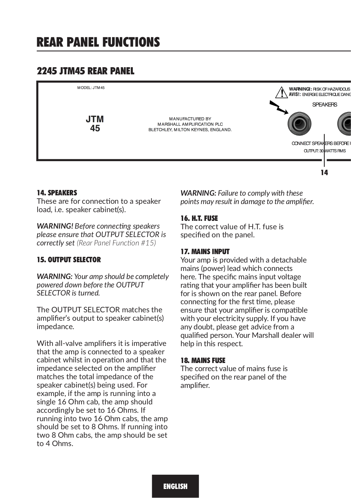
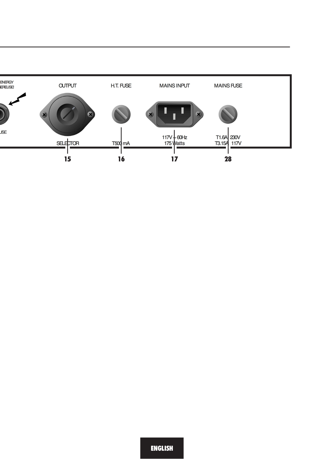
DSL1HR
dsl201
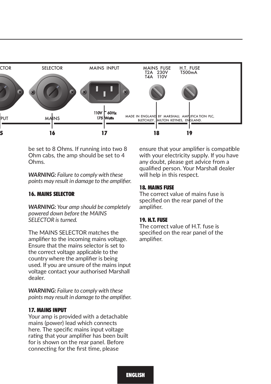
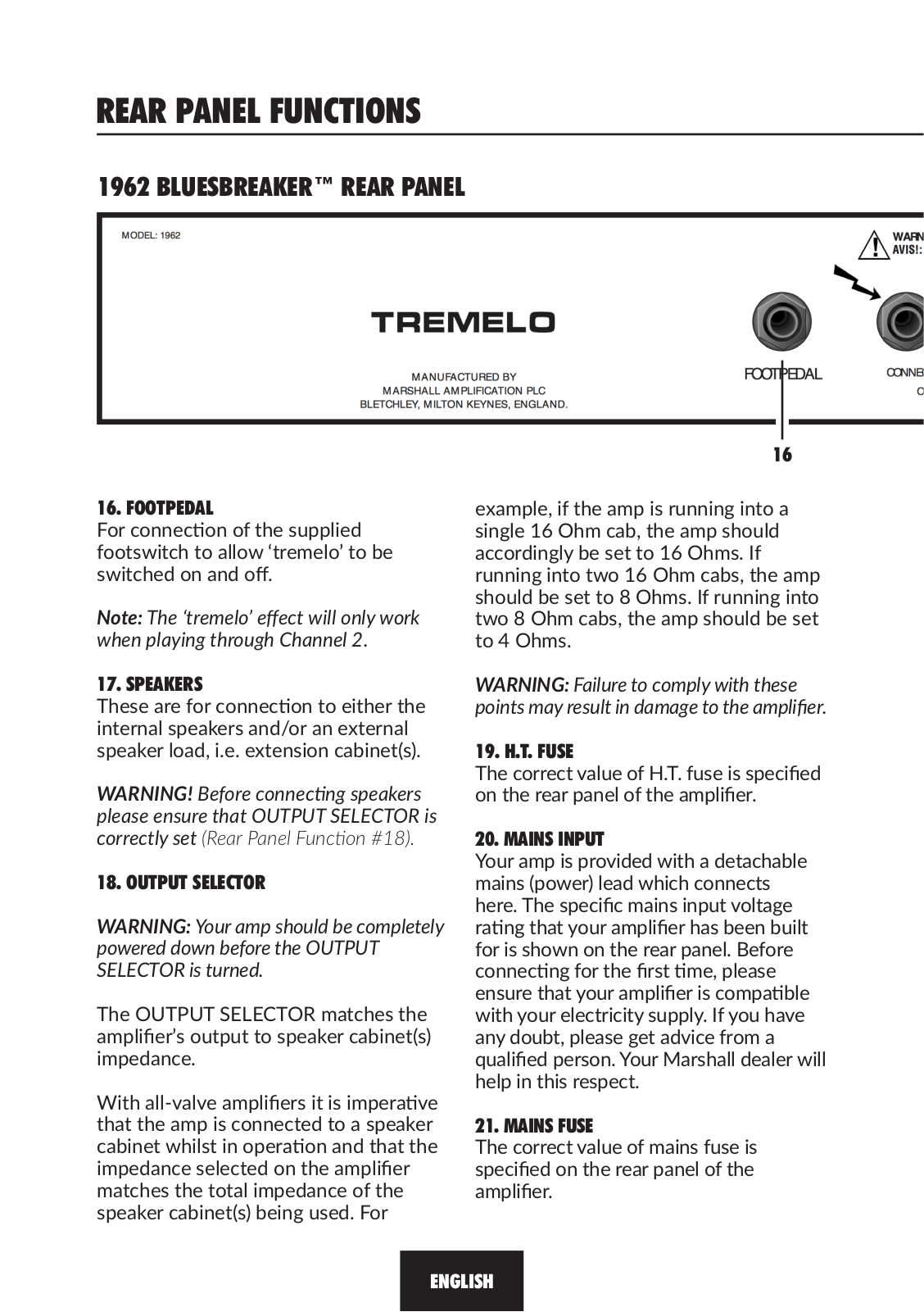
DSL20CR
DSL20HR
DSL40C
DSL40CR
DSL50
DSL5C
DSL5CR
E
Echohead EH-1
ED1
Emberton
2
extension cabinet
G
Guv`nor Plus GV-2
H
HANDWIRED CABINETS
HEADPHONES
HST13
I
II Acton
J
Jackhammer
Jackhammer JH-1
JCM-1C
JCM-1H
jcm2
4
JCM 200
jcm2000
14
jcm2-60-02
JCM-6
3
jcm600
2
JCM-600-601-602-Preamp
jcm800
16
JCM800 2203
jcm 900
11
JCM900 4100
JH-1
2
JMD 1
jmp1
5
JMP-1C
JMP-1H
jmp52
Joe Satriani
jtm100
2
JTM-1C
JTM-1H
jtm3
2
jtm30
3
jtm45
6
JTM45 2245
jtm60
4
jtm600
JTM Series
JVM
JVM-1C
JVM-1H
JVM410C
JVM410H
JVM410HJS
K
KILBURN
4
Kilburn II
8
Kilburn II Black + Major III BT
2
L
lead100
lead12
M
MA100C
MA100H
MA50C
MA50H
Major
2
Major Brown
Major II
3
Major II Bluetooth
4
Major II Brown
MAJOR III
2
Major III Bluetooth
2
MAJOR III BT
MAJOR III VOICE
mastervolume
MB15
MB30
M-CODE50-U
M-DSL100HR-U
MF-110-XMC
MF-220-XMC
MF280
MF3.2BLK-EU
MF350
MF400
MF4.4BLK-EU
MG10
3
MG100FX
2
MG100HCFX
MG100HF
MG101CFX
MG101GFX
MG102CFX
MG10G MG Gold
MG Series
3
M-MG101GFX-U
M-MX112R-U
Loading...
Loading...
Nothing found
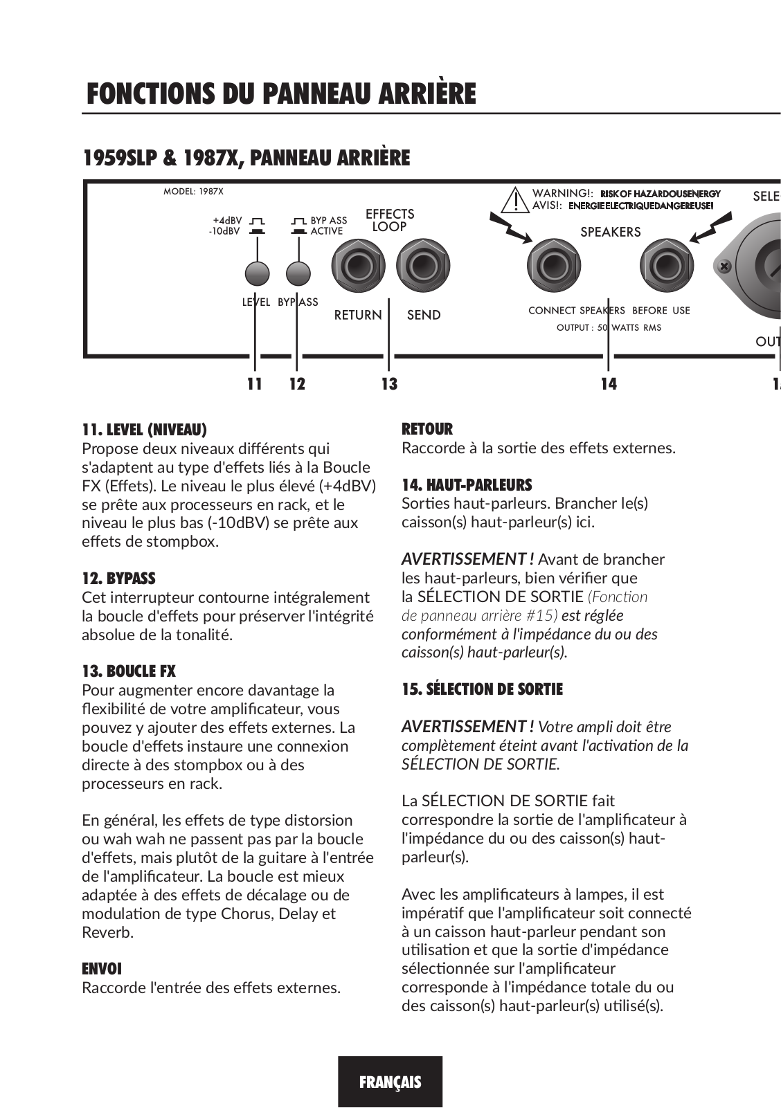
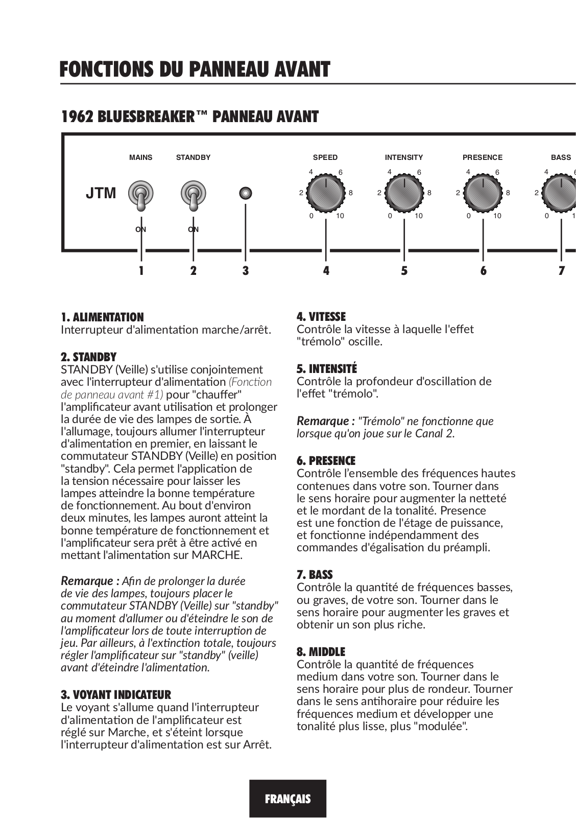
JTM45 2245
OWNER’S MANUAL
84 pgs
6.95 Mb
0
Table of contents
Loading...
Marshall JTM45 2245 OWNER’S MANUAL
...
Marshall OWNER’S MANUAL
Download
Specifications and Main Features
Frequently Asked Questions
User Manual
Download
Loading...
+
58
hidden pages
Unhide
You need points to download manuals.
1 point = 1 manual.
You can buy points or you can get point for every manual you upload.
Buy points
Upload your manuals
 Loading...