

Page 1
&
OWNER’S MANUAL
Page 2
WARNING! IMPORTANT SAFETY INSTRUCTIONS
WARNING! IMPORTANT SETUP INFORMATION
1) Read these instructions.
2) Keep these instructions.
3) Heed all warnings.
4) Follow all instructions.
5) Do not use this apparatus near water.
6) Clean only with dry cloth.
7) Do not install near any heat sources
such as radiators, heat registers, stoves, or
other apparatus (including ampliers) that
produce heat.
8) Do not defeat the safety purpose of
the polarized or grounding-type plug. A
polarized plug has two blades with one
wider than the other. A grounding type
plug has two blades and a third grounding
This “bolt of lightning” symbol indicates uninsulated material
within your unit may cause an electric shock. For the safety of
everyone in your household, please do not remove product covering.
The “exclamation point” calls attention to features for which
you should read the enclosed literature closely to prevent
operating and maintenance problems.
prong. The wide blade or the third prong
are provided for your safety. If the provided
plug does not t into your outlet, consult an
electrician for replacement of the obsolete
outlet.
9) Protect the power cord from being
walked on or pinched particularly at plugs,
convenience receptacles, and the point
where they exit from the apparatus.
10) Only use attachments/accessories
specied by the manufacturer.
11) Unplug this apparatus during lightning
storms or when unused for long periods of
time.
12) Refer all servicing to qualied service
personnel. Servicing is required when
the apparatus has been damaged in any
COMPLIANCE STATEMENT
This device complies with Part
15 of the FCC Rules.
Operation is subject to the
following two conditions: (1)
This device may not cause
harmful interference, and (2)
This device must accept any
interference received, including
interference that may cause
undesired operation.
Warning: Changes or
modications to this unit not
expressly approved by the party
responsible for compliance
could void the user’s authority
to operate the equipment.
Note: This equipment has been
tested and found to comply
with the limits for a Class B
digital device, pursuant to
Part 15 of the FCC Rules.
These limits are designed to
provide reasonable protection
against harmful interference in
a residential installation. This
equipment generates, uses and
can radiate radio frequency
energy and, if not installed
and used in accordance with
the instructions, may cause
harmful interference to radio
communications. However,
there is no guarantee that
interference will not occur
in a particular installation. If
this equipment does cause
harmful interference to radio or
television reception, which can
be determined by turning the
equipment off and on, the user
is encouraged to try to correct
the interference by one or more
of the following measures:
- Reorient or relocate the
receiving antenna.
- Increase the separation
between the equipment and
receiver.
- Connect the equipment into
an outlet on a circuit different
from that to which the receiver
is connected.
way, such as power-supply cord or plug
is damaged, liquid has been spilled or
objects have fallen into the apparatus,
the apparatus has been exposed to rain or
moisture, does not operate normally, or has
been dropped.
13) WARNING: To reduce the risk of re or
electric shock, do not expose this apparatus
to rain or moisture.
14) The appliance coupler is used as the
disconnect device, the disconnect device
shall remain readily operable.
15) The apparatus shall not be exposed to
dripping or splashing and that no objects
lled with liquid, such as vases, shall be
placed on the apparatus.
- Consult the dealer or
an experienced radio/TV
technician for help.
This equipment complies
with FCC RF radiation
exposure limits set forth for an
uncontrolled environment. This
equipment should be installed
and operated with a minimum
distance of 20 centimeters
between the radiator and your
body.
Industry Canada caution.
This device complies with
Industry Canada licenceexempt RSS standard(s).
Operation is subject to the
following two conditions:
(1) This device may not cause
interference, and (2) This device
must accept any interference,
including interference that may
cause undesired operation of
the device.
Francais:
Le présent appareil est
conforme aux CNR d’Industrie
Canada applicables aux
appareils radio exempts de
licence.
L’exploitation est autorisée aux
deux conditions suivantes:
(1) l’appareil ne doit pas
produire de brouillage, et
(2) l’utilisateur de l’appareil
doit accepter tout brouillage
radioélectrique subi, même si le
brouillage est susceptible
d’en compromettre le
fonctionnement.
2200
BEFORE GOING ANY FURTHER
Ensure that the specic mains input voltage rating that your amplier has been
manufactured for matches your electricity supply. This is indicated on the rear panel of
the amplier.
Your amplier is provided with a detachable mains (power) lead, which should be
connected to the MAINS INPUT socket on the rear panel of the amplier (#24 in this
manual) before the mains electricity outlet.
INTRODUCTION
CODE is a new generation of Marshall amplier. Fully programmable, CODE combines
authentic modelling of classic and contemporary Marshall tones with professional
quality FX. CODE preamp, power amp and speaker cabinet models have been developed
in collaboration with audio software pioneers Softube to create Marshall-Softube
(MST) modelling. Featuring Bluetooth® & USB connectivity, and Marshall Gateway™
compatibility, CODE is a powerful tool that lets you make music your way.
OVERVIEW
CODE is loaded with sonic possibilities. It has 14 MST preamps, 4 MST power amps
and 8 MST speaker cabinets. CODE features 24 FX: including Compressor, stompbox
Distortions, Auto Wah, Pitch Shifter, Chorus, Vibrato, Phaser, Vibes, Flanger and Tremolo.
It includes Studio, Vintage, Multi and Reverse Delays, Tap Tempo, and studio quality
Reverbs. Including Gate, you can have up to 5 FX simultaneously.
Using the Marshall Gateway App for your iOS or Android device you can control CODE’s
settings remotely via Bluetooth and share Presets with other CODE users. You can stream
audio from your device, computer or music player through CODE’s speaker or headphones
for practice, or jam along with tracks from your music library. Connect via USB to use your
CODE amplier as a DAW interface.
We sincerely hope that you enjoy your CODE amplier and we wish you every success,
whatever your performance situation. Thank you for choosing Marshall.
- The Marshall Team
CODE100 TECHNICAL SPECIFICATION
Power (RMS)
Presets
Speaker
Footcontroller
Weight
Size (in mm)
Connectivity
100 Watt (at 8 Ohm)
100 User editable Presets
2 x 12” Custom Voiced (CODE100 combo)
4-Way Programmable (PEDL-91009, sold separately)
CODE100: 21.0kg & CODE100H: 8.9kg
CODE100: 700 x 280x 480 & CODE100H: 525x 200 x 220
Bluetooth
®
4.0 & USB 2.0
ENGLISH
ENGLISH
Page 3

MARSHALL AMPLIFIER HISTORY
AMPLIFIER HISTORY (CONT.)
MST modelling recreates the tonal and sonic characteristics of some of the most successful
and respected amplier preamps from the past fty plus years.
JTM45™
The JTM45 was the rst Marshall amplier. It was made in 1962 by Jim Marshall and his
small team of engineers in a workshop at his music store in Hanwell, London. This 30 Watt
two channel amplier began a revolution that changed forever the sound of rock and
blues music. The JTM45 is still made today as part of the Vintage Re-Issue™ Series and
Handwired™ Series.
1962 Bluesbreaker™
The 1962 Bluesbreaker was the rst combo made by Marshall. Launched in 1965, it had
two 12” speakers with an output of 30 Watts. The 1962 was famously used by Eric Clapton
on the inuential blues album ‘John Mayall’s Bluesbreakers’ in 1966 – hence the 1962’s
‘Bluesbreaker’ nickname. The 1962 Bluesbreaker is still made today as part of the Vintage
Re-Issue Series™ and Handwired™ Series.
1959™ Plexi™
To the minds and ears of many, the 100 Watt Super Lead heads of the mid to late 1960s are
the holy grail of great rock tone. Being non-master-volume, when cranked, the 1959 power
valves overdrive producing highly responsive, harmonically rich tones. The 1959 amplier
is still made today as part of the Vintage Re-Issue Series™ and Handwired™ Series.
JCM800 2203™
The 2203 is one of the most important ampliers Marshall has ever made. It evolved in the
‘70s from the JMP and 1959 Plexi heads. In the ‘80s the 2203 became the JCM800 2203
we know today: a straightforward single channel amplier that was favoured by the heavy
metal scene that dominated much of that decade. Its popularity remained well into the ‘90s
with the emergence of Grunge and Britpop, and it’s still revered today and is considered
the benchmark by which modern all metal ampliers are measured.
JCM2555™ Silver Jubilee™
The 25/50 Silver Jubilee Series was created in 1987 to celebrate the 25th anniversary of
the founding of Marshall Amplication and 50 years of Jim Marshall being in the music
business. Based on the JCM800 2203 and 2204™ Master Volume models, Silver Jubilee
ampliers had a special preamp circuit that featured three gain ‘modes’ which were Clean,
Rhythm Clip and a switchable Lead Channel. The 2555 was the 100 Watt head in the
Jubilee series, which was a limited edition. By popular demand the JCM2555 was re-issued
as the 2555X™ in 2015.
JCM2000™ DSL100™
Launched in 1997, the JCM2000 Dual Super Lead’s ‘dual mode’ design meant that guitarists
could choose either a Clean or Crunch tone from the Classic Gain Channel, whilst the
Ultra Gain Channel provided two lead sounds: Lead 1 & Lead 2. This tonal versatility was
aided by the Deep and Tone Shift features. It is the JCM2000 DSL100’s tonal range and
versatility that made it massively popular in its day, so much so, that its legacy lives on in
the current DSL Series.
JVM410H™
When the JVM410H launched in 2006 it caused quite a stir. This 100 Watt head is an allvalve tonal monster that has four channels, each with three modes: Green, Orange and
Red, offering guitarists a range of 12 unique tones. Each mode recongures the channel
gain stages in order to develop different amounts of gain and tone. The JVM410H’s vast
tonal spectrum makes it the most versatile amplier Marshall has ever made, used by many
professional players.
POWER AMPLIFIERS
MST modelling recreates four classic and vintage valve power output topologies. A valve
power stage is a vital part of an all-valve amplier’s sound and its tonal character.
SPEAKER CABINETS
Marshall speaker cabinets are perhaps as famous as Marshall ampliers. The iconic 4 x 12”
design has changed little since Jim Marshall designed the rst one in 1965. Since then the
Marshall 4 x 12” has become the touchstone for all other speaker cabinets. MST modelling
recreates the sonic characteristics of eight classic Marshall speaker cabinets, including a
variety of 4 x 12”, 2 x 12” & 1 x 12” speaker congurations. Marshall speaker cabinets differ
not only in their speaker congurations, but in the speakers that they use, how they are
wired and the size of the cabinet.
GETTING STARTED
To begin using CODE:
• Ensure that the power ON/OFF switch is set to the OFF position (#14 in this manual).
• Connect the supplied power cord to the MAINS INPUT (#24 in this manual) before
plugging into the mains electricity supply.
• If using the CODE100H head, connect the supplied speaker cable to the speaker cabinet
and to the SPEAKER jack socket on the amplier’s rear panel (#26 in this manual).
• Plug your guitar cable into the amplier INPUT jack socket (#2 in this manual).
• Set the MASTER volume control to zero (#8 in this manual).
• Turn the amplier ON using the ON/OFF switch.
• Gradually turn the MASTER up to your desired volume level.
• Turn the PRESET selector to explore your CODE amplier’s factory Presets
(#9 in this manual).
ENGLISH
ENGLISH
Page 4
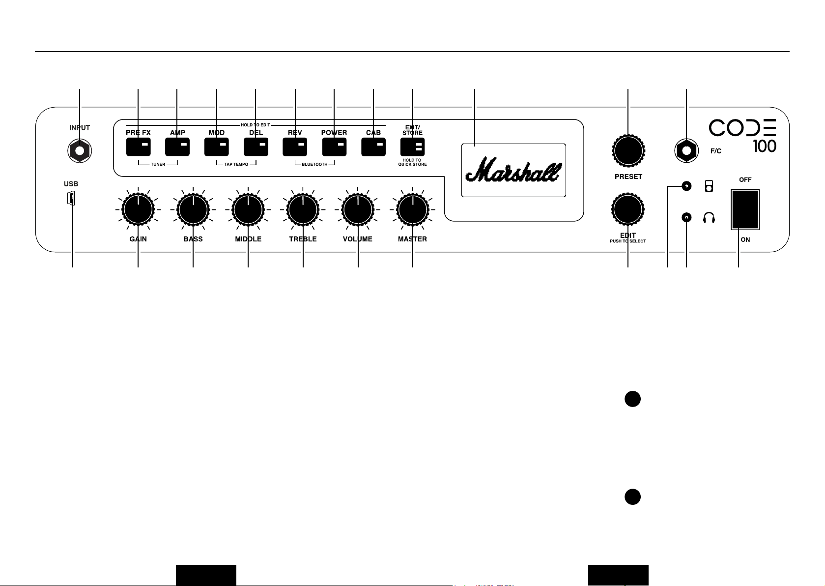
FRONT PANEL FUNCTIONS
2 15 16 17 18 19 20 21 22
7 8
1. USB
Connect via USB to use CODE as a DAW interface, to play tracks from your music library,
to get rmware updates and control via MIDI.
To record with CODE using your DAW:
• Connect to your computer via USB.
• Select your CODE amplier as the input
source on your computer and within
your DAW.
To stream audio from your computer
through CODE:
• Connect to your computer via USB.
• Select your CODE amplier as your
computer’s output source.
• Use the MASTER control to adjust the
volume level (#8 in this manual).
To get CODE rmware updates:
http://my.marshall.com/Downloads/
FirmwareUpdate
Follow this link to quickly and easily keep
your CODE amplier’s rmware up to date.
MIDI data:
• Your CODE amplier can also send and
receive MIDI data related to the front
panel controls via the USB.
23 11
9
10 131 143 4 5 6 12
2. INPUT
Use this jack socket to connect your
guitar to the amplier. Use a good quality
screened/shielded guitar cable to help
prevent noise interference.
3. GAIN
Controls the amount of GAIN introduced to
a Preset. The higher the GAIN, the harder
the preamp is driven.
4. BASS
Turning the BASS control will adjust the
warmth and low-end depth of your sound.
5. MIDDLE
Adjusting the MIDDLE control will vary the
amount of body in your sound by boosting
or cutting midrange frequencies.
6. TREBLE
Increasing the TREBLE will make your
sound brighter and more cutting. Turning
the TREBLE down will decrease tonal edge
and make the sound softer.
7. VOLUME
Controls the volume level within a selected
Preset.
Because GAIN, BASS, MIDDLE, TREBLE
!
& VOLUME are stored as part of a Preset,
these panel tone controls only become active
when they are used. This means that until
they are turned their position is not related to
their setting within a Preset. When you turn
a tone control it becomes active. The display
screen will show its current setting and the
stored setting.
When a GAIN, BASS, MIDDLE, TREBLE
!
or VOLUME control is activated the
EXIT/STORE LED will ash red to show that
the Preset’s stored settings have changed.
ENGLISH
ENGLISH
Page 5
FRONT PANEL FUNCTIONS (CONT.)
Marshall
MOD
DELAY
REVERB
1718
20
21
A:>>|<<
FRONT PANEL FUNCTIONS (CONT.)
8. MASTER
current Section Switch settings.
Controls the overall volume level of your
CODE amplier.
MASTER volume control settings are not
!
stored as part of a Preset.
To discover how to edit a Preset, go to
!
‘EDITING A PRESET’ in this manual.
11. F/C
Use this jack socket to connect the
9. PRESET
A Preset is a combination of preamp, power
amp & speaker models, with tonal settings
and FX: Chorus, Flanger, Tremolo, Delay
etc, stored to a single location within your
CODE amplier’s memory. This is like a
‘snapshot’ of the whole amplier’s settings
(excluding MASTER), which can be recalled
using the PRESET selector, or with the
optional CODE footcontroller.
Turn the PRESET selector to explore your
CODE amplier’s factory Presets.
supplied 2-way footswitch for scrolling
through Presets, or to connect the CODE
programable footcontroller (PEDL-91009
sold separately).
12. MP3 PLAYER INPUT
Use this dedicated mini-jack socket to
connect an audio player to practice with or
jam along to music.
13. HEADPHONE OUTPUT
Use this mini-jack socket to connect
headphones for ‘silent’ practice. This can
also be used as a line out.
14. ON/OFF
10. EDIT
This is the mains power ON/OFF switch.
Use the EDIT selector to deep edit a Preset.
Push the EDIT selector to preview the
stored Gain, Bass, Middle, Treble & Volume
settings. Turn the EDIT selector to view the
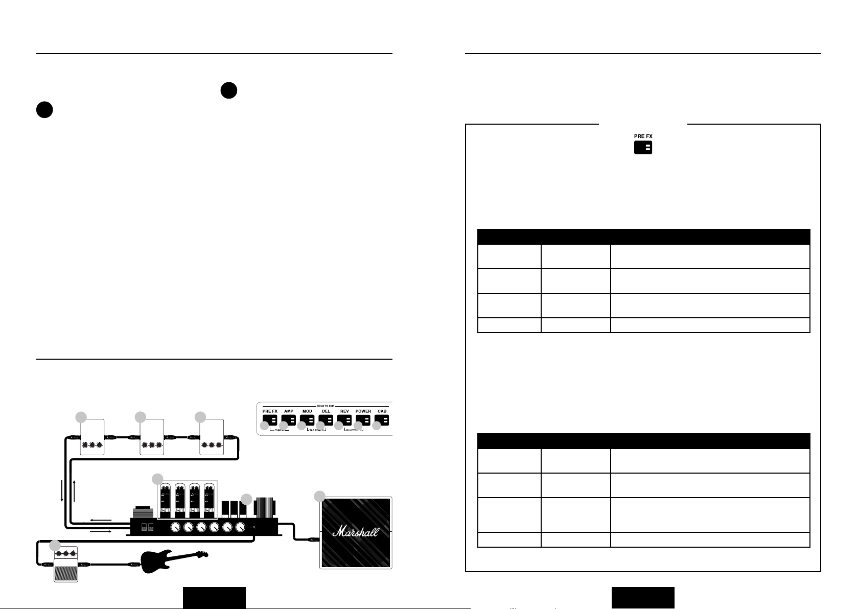
SECTION SWITCHES (15 - 21)
The Section Switches represent different ‘sections’ in the guitar signal chain. This is the
route that a guitar signal travels through a conventional amplier setup from the guitar to
the loud speaker(s).
1718
MOD
POWER AMP
161617
15
Pressing the Section Switches (#15 – #21 in
this manual) will activate (Red LED on) and
bypass (LED off) that Section.
PREAMP
16
18
21
CABINET
19
21
20
15
STOMPBOX
19
REVERB
DELAY
20
15. PRE FX
This is where you will nd FX that would typically plug into a conventional amplier setup
between the guitar and the amplier’s input. These FX would typically be in pedal form,
and also known as ‘stompboxes’. The ‘stompbox’ FX in the PRE FX section are:
‘STOMPBOX’ FX
Compressor
Compressor affects an audio signal’s dynamic range. CODE’s compressor decreases,
or ‘compresses’, any part of your guitar sound that peaks above a certain threshold.
Any part of your guitar sound that remains below the threshold is unaffected.
Compressor can add clarity and consistency to your guitar sound whether clean or
overdriven. Compressor’s editable parameters are:
PARAMETER VALUE RANGE DESCRIPTION
Tone 0 - 10 Adjusts the Compressor’s higher and lower
frequencies.
Ratio 0 - 10 Controls how much Compression is applied to a signal
above the threshold.
Compression 0 - 10 Adjusts the point at which Compression is applied to
the signal.
Level 0 - 10 Controls the overall volume level of the Compressor.
Distortion
CODE’s stompbox Distortion’s three Modes simulate solid-state Distortion and
Overdrive FX pedals. GUV Mode is a Marshall Guv’nor™ with Drive and Tone
controls. ODR & DIS Modes provide avours of classic overdrive and distortion
stompboxes. Stompbox Distortion is particularly effective when used with classic
and vintage MST preamp models to provide more drive and sustain. Distortion’s
editable parameters are:
PARAMETER VALUE RANGE DESCRIPTION
Mode GUV, ODR & DIS Marshall Guv’nor, Classic OD pedal
& Classic Distortion pedal.
Drive 0 - 10 Controls the amount of Overdrive or Distortion
applied to the signal.
Tone 0 - 10 Adjusts the amount of upper mid and higher frequency
content in the Overdrive or Distortion before the
signal reaches the amplier panel tone controls.
Level 0 - 10 Controls Distortion’s overall volume level.
ENGLISH
ENGLISH
Page 6

FRONT PANEL FUNCTIONS (CONT.)
A:>>|<<
A:>>|<<
FRONT PANEL FUNCTIONS (CONT.)
15. PRE FX (CONT.)
‘STOMPBOX’ FX
Auto Wah
Auto Wah is a dynamic lter, similar to a Wah Wah pedal. A Wah Wah pedal has a
‘rocker’ footplate to control the frequency at which the lter operates. Auto Wah has
no ‘rocker’ footplate, so in ENV Mode the rocker automation responds to input level.
In LFO Mode the rocker motion is fully automated. Auto Wah’s editable parameters
are:
PARAMETER VALUE RANGE DESCRIPTION
Mode ENV & LFO Envelope Filter & Low Frequency Oscillator.
Frequency 0 - 10 Controls the resting frequency, or fully closed posi-
tion, of the Wah, thereby setting how far the lter
opens when playing.
Sensitivity 0 - 10 ENV Mode: Controls how much the Wah opens in
relation to the pick attack.
LFO Mode: Controls the speed at which the Wah
opens and closes. Set to zero and Auto Wah acts as a
xed rocker Wah.
Resonance 0 - 10 Adjusts the magnitude, bandwidth and shape of the
lter’s resonant peak.
Pitch Shifter
Pitch Shifter generates chromatic harmonies with the ability to ne tune. This
enables you to pitch up or down to produce octaves or 3rd, 4th or 5th harmonies.
Pitch Shifter can also produce more discordant, quirkier sounds. Pitch Shifter’s
editable parameters are:
PARAMETER VALUE RANGE DESCRIPTION
Semitone -12 to +12 Selects the pitch of the generated note chromatically
from an octave below to an octave above the note
played.
Fine Tune -50 to +50 Fine tunes the pitch of the generated note.
Regeneration 0 - 10 Adjusts the percentage of the signal fed back into the
Pitch Shifter. Set to zero for a single pitch shifted tone.
Mix 0 - 10 Adjusts the balance between the guitar signal and the
generated note.
16. AMP
AMP is short for preamp. MST modelling faithfully recreates classic and modern Marshall
valve tones as well as other famous valve amp tones. Each AMP model creates an authentic
preamp setting. The MST preamp models are classied into three groups: Clean, Crunch &
Overdrive.
Your CODE amplier’s MST preamp models are:
PREAMP MODELS
CLEAN
JTM45™
CL DSL
CL American
CL JVM
Acoustic Simulator
JTM45 2245 on a clean setting.
DSL100H on the Classic Gain Channel, Clean setting.
Classic American pure-valve sound.
JVM410H on the Clean Channel in Green Mode.
Simulates the sound of an electro-acoustic guitar.
CRUNCH
Bluesbreaker™
Plexi™
CR American
JCM800™
‘50s British
1962 Bluesbreaker combo overdriven.
1959SLP Overdriven.
Classic American valve overdrive.
JCM800 2203 overdriven (high sensitivity input).
Classic British valve combo overdrive.
OVERDRIVE
OD JVM
OD DSL
OD American
OD Silver Jubilee
JVM410H on OD1 Channel in Red Mode.
JCM2000 DSL Lead 2 Channel.
Classic American higher gain overdrive.
JCM2555 Silver Jubilee Lead Channel.
NATURAL
The Natural preamp is designed to be used with external FX without the tonal
colour of an MST modelled preamp. It provides EQ for tonal shaping and access
to the Gate.
GATE
If the noise Gate is applied, when your sound level drops below the set threshold
it will activate, preventing any signal below that threshold from passing through.
It progressively attenuates the guitar signal, following its dynamics, to suppress
unwanted noise.
PARAMETER VALUE RANGE DESCRIPTION
Threshold 0 - 10 Sets the point at which the Gate begins to close.
ENGLISH
ENGLISH
Page 7

FRONT PANEL FUNCTIONS (CONT.)
A:>>|<<
A:>>|<<
A:>>|<<
FRONT PANEL FUNCTIONS (CONT.)
17. MOD
MOD is short for Modulation. Modulation FX in a conventional setup can be in stompbox
or rack form and often connect via an amplier’s FX loop:
MODULATION FX
Chorus
Chorus and Vibrato FX apply a subtle pitch variation to the guitar signal taking your
sound from shimmering, delicate undulations to full on wobble. This can add depth
and width to clean sounds and fatten up solos. Chorus’s editable parameters are:
PARAMETER VALUE RANGE DESCRIPTION
Mode CLS & VIB Classic Chorus & Vibrato.
Speed 0 - 10 Controls the rate of the Chorus or Vibrato effect.
Depth 0 - 10 Adjusts the depth of the Chorus or Vibrato effect.
Tone 0 - 10 Boosts or cuts high & low frequency content in the
sound.
Flanger
Flanger can produce Chorus-like sounds, but is more vivid and is harmonically more
complex. It can create weird and wonderful sonic textures, like ‘jet plane’ Doppler FX
and resonant metallic whooshes. Flanger’s editable parameters are:
PARAMETER VALUE RANGE DESCRIPTION
Mode JET & MET Jet Flanger & Metallic Flanger.
Speed 0 - 10 Controls the rate of the Flanger effect.
Depth 0 - 10 Adjusts the depth of the Flanger effect.
Regeneration 0 - 10 Adjusts the amount of signal that is fed back to the
effect input, which makes the Flanger effect sharper.
17. MOD (CONT.)
MODULATION FX
Tremolo
The cool sounding Tremolo effect is created by the signal amplitude being modulated
up and down. Tremolo can produce a variety of sonic characteristics from delicate
shimmer to heavy Tremolo throb. Tremolo’s editable parameters are:
PARAMETER VALUE RANGE DESCRIPTION
Mode VLV & SQR Valve Tremolo & Square Wave Tremolo.
Speed 0 - 10 Controls the rate of Tremolo oscillation.
Depth 0 - 10 Adjusts the depth of the Tremolo effect.
Skew -50 to +50 Adjusts the shape of the waveform that is performing
the amplitude modulation. The variation of the wave
shape across the value range moves between vintage
and modern sounding Tremolo.
18. DEL
DEL is short for Delay. Delay FX in a conventional setup can be in stompbox or rack form
and often connect via an amplier’s FX loop. When you select DEL the switch’s LED will
remain lit red for two seconds before ashing to indicate the current Delay tempo. CODE’s
Delay FX are:
DELAY TYPES
Phaser
Phaser uses all-pass lters to shift the guitar signal very slightly, modulating the
shifted, or phased, signal in relation to the original signal produces the classic Phaser
sound - great for tight funky lines, sweeps and swells. Phaser’s editable parameters
are:
PARAMETER VALUE RANGE DESCRIPTION
Mode CLS & VBE Classic Phaser & Vibe.
Speed 0 - 10 Controls the rate of the Phaser or Vibe effect.
Depth 0 - 10 Adjusts the depth of the Phaser or Vibe effect.
Regeneration 0 - 10 Adjusts the amount of signal that is fed back to the
effect input, which makes the Phaser effect sharper.
ENGLISH
Studio
Studio Delay is a high delity delay line. Its longer delay time enables you to create
layered loops of up to 4 seconds. Studio Delay’s editable parameters are:
PARAMETER VALUE RANGE DESCRIPTION
Time 0 - 4000 Controls the Delay repeat time in milliseconds.
Feedback 0 - 10 Adjusts the number of Delay repeats.
Frequency 0 - 10 Adjusts the amount of higher frequency content in the
Delay repeats.
Level 0 - 10 Adjusts the level of the Delay effect.
ENGLISH
Page 8

FRONT PANEL FUNCTIONS (CONT.)
A:>>|<<
A:>>|<<
A:>>|<<
FRONT PANEL FUNCTIONS (CONT.)
18. DEL (CONT.)
DELAY TYPES
Vintage
Vintage Delay recreates the sound of analogue delays. Vintage Delay’s editable
parameters are:
PARAMETER VALUE RANGE DESCRIPTION
Time 0 - 4000 Controls the Delay repeat time in milliseconds.
Feedback 0 - 10 Adjusts the number of Delay repeats.
Age 0 - 10 Adjusts the amount ‘utter’ and higher frequency
roll-off for a more vintage sounding Delay
Level 0 - 10 Adjusts the volume level of the Delay effect.
Multi
Multi Delay adds a rhythmic repeat for more complex delay patterns. Multi Delay’s
editable parameters are:
PARAMETER VALUE RANGE DESCRIPTION
Time 0 - 4000 Controls the Delay repeat time in milliseconds.
Feedback 0 - 10 Adjusts the number of Delay repeats.
Tap Pattern 1 - 4 Select from four different Delay repeat patterns
Level 0 - 10 Adjusts the volume level of the Delay effect.
18. DEL (CONT.)
DELAY TYPES
Tap Tempo
Set the Delay time by tapping the EDIT selector, or by tapping an assigned button on
the optional CODE footcontroller. This enables you to quickly and easily match the
Delay time with the tempo of the music you are playing.
To activate TAP TEMPO:
• Press MOD and DEL Section Switches together.
• The display screen will show the Delay time in milliseconds.
• Either turn the EDIT selector to select the delay time in milliseconds or tap it
repeatedly to nd your delay time or to match a tempo.
• Press EXIT/STORE once to exit TAP TEMPO and return to the main Preset screen.
The DEL Section Switch LED will ash in time to the current Delay time or tempo
!
when active.
18. REV
REV is short for Reverb. Reverb FX in a conventional amplier setup can be in stompbox
form, rack form or integrated within an amplier. Your CODE’s Reverb FX are:
REVERB TYPES
Reverse
Reverse Delay’s repeats run backwards. This can add texture and an eerie quality to
your sound. Reverse Delay’s editable parameters are:
PARAMETER VALUE RANGE DESCRIPTION
Time 0 - 4000 Controls the Delay repeat time in milliseconds.
Feedback 0 - 10 Adjusts the number of Delay repeats.
Frequency 0 - 10 Adjusts the amount of higher frequency content in the
Mix 0 - 10 Adjusts the level of the Delay effect relative to the
Delay repeats
unaffected signal. As the amount to Delay is increased,
the unaffected signal is decreased, and vice versa.
ENGLISH
Room
Room Reverb recreates the acoustic reections of small to larger rooms. Room
Reverb’s editable parameters are:
PARAMETER VALUE RANGE DESCRIPTION
Decay 0 - 10 Controls how long the it takes for the reections to
fade.
Pre-delay 0 - 10 Adjusts the amount of time before the rst reection
is heard.
Tone 0 - 10 Adjusts the amount of higher frequency content in the
reections.
Level 0 - 10 Adjusts the level of the Reverb effect.
ENGLISH
Page 9

FRONT PANEL FUNCTIONS (CONT.)
A:>>|<<
A:>>|<<
A:>>|<<
FRONT PANEL FUNCTIONS (CONT.)
19. REV (CONT.)
REVERB TYPES
Hall
Hall Reverb recreates the longer acoustic reections of a hall-sized space. Hall
Reverb’s editable parameters are:
PARAMETER VALUE RANGE DESCRIPTION
Decay 0 - 10 Controls how long the it takes for the reections to
fade.
Pre-delay 0 - 10 Adjusts the amount of time before the rst reection
is heard.
Tone 0 - 10 Adjusts the amount of higher frequency content in the
reections.
Level 0 - 10 Adjusts the level of the Reverb effect.
Spring
Spring Reverb is a classic, analogue way of creating Reverb FX. Conventional Spring
Reverb uses a metal tray containing rows of springs. The guitar signal passes along
the springs creating a vintage sounding Reverb effect. Spring Reverb’s editable
parameters are:
PARAMETER VALUE RANGE DESCRIPTION
Decay 0 - 10 Controls how long the it takes for the reections to
fade.
Pre-delay 0 - 10 Adjusts the amount of time before the rst reection
is heard.
Tone 0 - 10 Adjusts the amount of higher frequency content in the
reections.
Level 0 - 10 Adjusts the level of the Reverb effect applied to the
unaffected signal.
19. REV (CONT.)
REVERB TYPES
Stadium
Stadium Reverb recreates the acoustic reections of a very large space. Stadium
Reverb’s editable parameters are:
PARAMETER VALUE RANGE DESCRIPTION
Decay 0 - 10 Controls how long the it takes for the reections to
fade.
Pre-delay 0 - 10 Adjusts the amount of time before the rst reection
is heard.
Tone 0 - 10 Adjusts the amount of higher frequency content in the
reections.
Level 0 - 10 Adjusts the level of the Reverb effect.
20. POWER
This is the section of a conventional amplier that provides power to drive the speaker(s).
The power valves are an integral part of how an all-valve amplier sounds. MST modelling
faithfully recreates the four valve power amps models in CODE:
POWER AMP MODELS
Classic Marshall 100W
Class A/B 100 Watt with EL34 valves.
PARAMETER VALUE RANGE DESCRIPTION
Presence 0 - 10 In a conventional amplier Presence is a power stage
function that adds higher frequency content to the
sound.
Resonance 0 - 10 In a conventional amplier Resonance is a power stage
function that adds lower end thud to the sound.
ENGLISH
ENGLISH
Page 10

FRONT PANEL FUNCTIONS (CONT.)
A:>>|<<
A:>>|<<
FRONT PANEL FUNCTIONS (CONT.)
20. POWER (CONT.)
POWER AMP MODELS
Vintage Marshall 30W
Class A/B 30 Watt with 5881 valves.
PARAMETER VALUE RANGE DESCRIPTION
Presence 0 - 10 In a conventional amplier Presence is a power stage
function that adds higher frequency content to the
sound.
Resonance 0 - 10 In a conventional amplier Resonance is a power stage
function that adds lower end thud to the sound.
British Class A
Class A 30 Watt with EL84 valves.
PARAMETER VALUE RANGE DESCRIPTION
Presence 0 - 10 In a conventional amplier Presence is a power stage
function that adds higher frequency content to the
sound.
Resonance 0 - 10 In a conventional amplier Resonance is a power stage
function that adds lower end thud to the sound.
21. CAB
CAB is short for Speaker Cabinet. A cab’s speaker conguration and its size play a signicant
role in the overall sound produced by the whole amplier setup.
The MST modelled speaker cabinets in your CODE amplier are faithful recreations of
classic Marshall cabs:
CABINET TYPES
1960
1960V
1960AX
1960HW
1936
1936V
1912
1974CX
22. EXIT/STORE
While on any screen pressing EXIT/STORE returns you to the main Preset screen.
Press and hold EXIT/STORE while on any screen to QUICK STORE your edited settings.
Your edited settings will store over the current Preset and the display will return you to
the main Preset screen.
To discover how to store and name a Preset, go to STORING A PRESET in this manual.
!
!
Classic 4 x 12” Celestion G12-T75 speakers.
4 x 12” with Celestion ‘Vintage 30’ speakers.
4 x 12” with Celestion G12M-25 speakers.
4 x 12” with Celestion G12H-30 speakers.
Classic 2 x 12” Celestion G12-T75 speakers.
2 x 12” with Celestion ‘Vintage 30’ speakers.
Classic 1 x 12” Celestion G12-B150 speakers.
1 x 12” Handwired with G12M-20 speaker.
American Class A/B
Class A/B 100 Watt with 6L6 valves.
PARAMETER VALUE RANGE DESCRIPTION
Presence 0 - 10 In a conventional amplier Presence is a power stage
Resonance 0 - 10 In a conventional amplier Resonance is a power stage
function that adds higher frequency content to the
sound.
function that adds lower end thud to the sound.
ENGLISH
23. DISPLAY
The Display Screen shows a Preset’s name, number, parameter settings and the tuner
display.
ENGLISH
Page 11

REAR PANEL FUNCTIONS
24 25 26
24. MAINS INPUT
Connects the amplier to the mains power supply.
The MAINS INPUT socket has an integrated fuse compartment. Ensure that the value
!
of a replacement fuse matches the labelling on the amplier rear panel. You MUST
ALWAYS switch the amplier OFF and disconnect it from the mains electricity supply
before attempting to access the fuse compartment. If in doubt, contact your Marshall
Dealer.
25. FX LOOP
Connect external FX pedals or a signal processor here. The FX LOOP is post DSP in the
signal chain.
EDITING A PRESET (CONT.)
• Turn the EDIT selector to edit the highlighted parameter. You will see the parameter
value change on the screen as you turn.
• When you are happy with your edited parameter value, push the EDIT selector to move
to the next parameter (if there is one).
• Turn the EDIT selector to edit the newly highlighted parameter.
• Repeat for all parameters and parameter values of the Sections that you wish to edit.
• When you are happy with your edited Preset you can store it to your CODE amplier’s
memory.
To learn how to store an edited Preset, refer to STORING A PRESET in this manual.
!
• If you wish exit without storing your edits, press EXIT/STORE (# 22 in this manual).
This will return you to the main Preset screen.
If you wish to keep your edited settings ensure that you store before moving off that
!
Preset.
26. SPEAKER OUTPUT (CODE100H ONLY)
Connect a speaker cabinet here.
IMPORTANT - Do NOT connect a speaker cabinet of less than 8 Ohm, and NEVER use
CODE100H without a spekaer cabinet connected.
!
EDITING A PRESET
To edit PRE FX, AMP, MOD, DEL, REV, POWER and CAB section settings:
• Hold down the Section Switch that you wish to edit (#15 - #21 in this manual).
• The display screen will show the current section’s settings.
• Turn the EDIT selector (#10 in this manual) to scroll through the different options within
the current
section: CL DSL, Plexi, JCM800, OD Silver Jubilee in AMP, or Chorus, Flanger,
Phaser, Tremolo in MOD, or Studio, Vintage, Multi, Reverse in DEL, for example.
• Push the EDIT selector to begin editing.
Speaker cabinet models are not editable.
!
ENGLISH
STORING A PRESET
To store an edited Preset, Store an edited Preset to a new location, and to rename an
edited Preset:
• When you have nished editing, press & hold EXIT/STORE briey until the Preset name
begins to auto-scroll to the left into the Preset number.
• If you wish to store your edited Preset to another location, turn the PRESET selector to
nd a new location, then press & hold EXIT/STORE until STORED appears on the display
screen.
Be sure that you want to store to the Preset location that you have selected, as the Preset
!
in that location will be overwritten.
To rename the edited Preset and store to the current location:
• While the Preset name auto-scrolls to the left, press & hold EXIT/STORE again briey
until the Preset name is displayed with arrows above and below the rst letter or
character.
• Turn the EDIT selector to change the letter or character.
• Turn the PRESET selector to move to the next letter or character, or back to a previous
letter or character.
• Repeat until you have renamed the Preset.
ENGLISH
Page 12

A:>>|<<
A:>>|<<
A:>>|<<
STORING A PRESET (CONT.)
GUITAR TUNER
The Section Switches act as naming shortcuts:
NAMING SHORTCUTS
PRE FX
AMP
MOD
DEL
REV
POWER
CAB
• To complete the store process, press & hold EXIT/STORE once more until STORED
appears on the display screen. Your edited Preset has now been stored to CODE’s
memory.
Clear
Number
Upper / Lower Case A
Upper / Lower Case
Space
Backspace
Cancel
BLUETOOTH
Pressing REV and POWER Section Switches together (#19 & #20 in this manual) accesses
the Bluetooth
• The display screen will show ‘Bluetooth:’ with your CODE amplier’s
pairing ID.
• The blue LED on EXIT/STORE (#22 in this manual) will ash while pairing.
• When paired, the blue LED will stop ashing and remain lit.
• When streaming audio, use the MASTER volume control or your music player to set the
volume level.
Streamed audio will bypass CODE’s panel features, with the exception of MASTER
!
volume.
The Marshall Gateway™ App enables you to control your CODE amplier remotely using
your iOS or Android device. Create a Marshall Cloud prole and sync your device to
manage your Preset library online. You can share your Presets, access featured Presets,
join the conversaion on the CODE Forum and more. Register and become part of the
CODE online community at: my.marshall.com. Download Marshall Gateway now from the
App Store or Google Play.
®
pairing function:
Pressing the PRE FX and AMP Section Switches (#15 & #16 in this manual) together
accesses the guitar TUNER:
• Pluck a string and the note you are playing will display.
• Tune the string until the name of the note you wish to tune to appears on the screen.
• The bar will move to the left if the note is at. The bar will move to the right if the note is
sharp.
• When the bar is dead centre, that string is tuned to the displayed note.
• Press EXIT/STORE to exit the Tuner.
FACTORY RESET
Performing a factory reset will return CODE’s Presets back to when it was new.
Before performing a factory reset, be sure that you want to overwrite all of your personal
!
Presets.
To perform a factory reset:
• Power OFF the amplier using the ON/OFF switch (#14 in this manual).
• Whilst holding down the AMP Section Switch, turn the power ON.
• The screen will display a notication that the amplier is about to be returned to its
factory settings.
• If you are sure that you want to perform a factory reset, press and hold the EXIT/STORE
switch to conrm (#22 in this manual).
• If you do not want to restore the factory presets, pressing any other switch will cancel the
factory reset operation and boot the amplier as normal.
ENGLISH
ENGLISH
Page 13

Marshall Amplication Plc,
Denbigh Road,
Manufacturer:
Kind of equipment: Audio Equipment
Type designation: CODE100, CODE100H
We, Marshall Amplication Plc, declare under our sole responsibility that the above listed products complies with the following
Directives:
1. EMC Directive 2014/30/EU;
2. Low Voltage Directive (LVD) 2014/35/EU;
3. R&TTE Directive 1999/5/EC.
The following harmonised standards have been applied:
1. EMC
2. LVD • EN 60065:2014
Health &
Safety
(Article 3(1)(a))
3. R&TTE
EMC
(Article 3(1)(b))
Spectrum
(Article 3(2))
Bletchley,
Milton Keynes,
Bucks,
United Kingdom
MK1 1DQ
• EN 55032:2012
• EN 55020:2007/A12:2016
• EN 61000-3-2:2014
• EN 61000-3-3:2013
• EN 62479:2010
• EN 60065:2014
• ETSI EN 301 489-1 V1.9.2:2011
• ETSI EN 301 489-17 V2.2.1:2012
• ETSI EN 300 328 V1.9.1:2015
NOTESDECLARATION OF CONFORMITY
Signature: Name: B. Moon Date: 1st May 2017
17
Name of the responsible party: Jam Industries USA, LLC
Address of the responsible party: 1649 Barclay Blvd, Buffalo Grove, IL 60089, United States of America.
Telephone number of the
responsible party:
Name of equipment: MD116D Guitar Ampliers
Model No.: CODE100, CODE100H
This device complies with part 15 of the FCC Rules. Operation is subject to the following two conditions: (1) This device may not cause
harmful interference, and (2) this device must accept any interference received, including interference that may cause undesired
operation.
800-877-6863
ENGLISH ENGLISH
Page 14

MARSHALLAMPS.COM
Marshall Amplication plc, Denbigh Road,
Bletchley, Milton Keynes, MK1 1DQ, England.
Telephone: +44 (0) 1908 375411 | Fax: +44 (0) 1908 376118
Registered in England. Registered Number: 805676
Whilst the information contained herein is correct at the time of publication, due to our policy of constant improvement
and development, Marshall Amplication plc reserves the right to alter specications without prior notice.
 Loading...