

Marshall 1974-Lead-Bass-18w Schematic
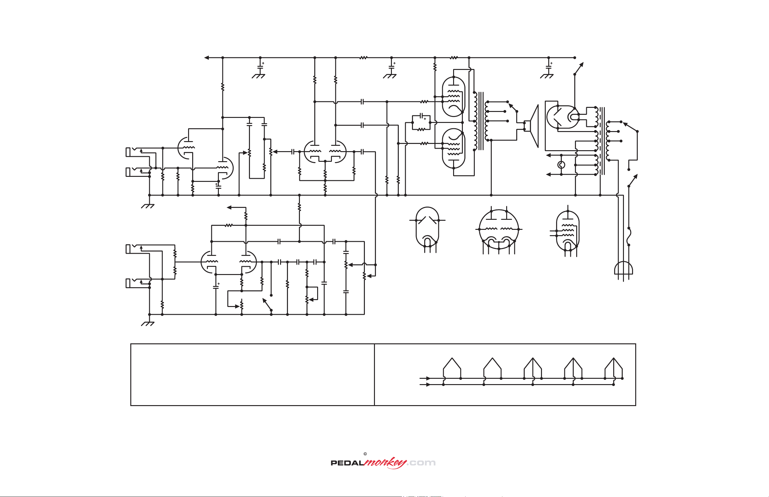
Marshall 18 Watt Combo Schematic
Revision 5
N
O
R
M
A
L
T
R
E
M
O
L
O
LO
J1
J2
HI
J3
LO
J4
HI
V1A
1
2
R3 R4
1Meg 1Meg
R2
820
R27
68K
R28
68K
R8
1Meg
3
A
V1
ECC83
50µF
C11
25v
V3A
6
7
C19
50µF
25v
R7
100K
V1B
7
8
R30
6
8
A
R12
220K
V3
ECC83
R14
820
C6
.01µF
Tone
500K-A
R1
100K
R11
100K
1
V3B
3
R10
2.2Meg
R32
Intensity
1K-L
R18 R19
100K 100K
C5
.005µF
V2A V2B
C1
.01µF
2
R31
Volume
500K-A
R9
470K
R29
470K
C15
.005µF .005µF
C8 C9 C10
.01µF .01µF .01µF
2
R24
470K
R26
1Meg
R33
Speed
2Meg-A
1
V2
ECC83
3
R13
.05µF
8
820
R17
47K
C12
R34
Tone
500K-A
C7
R6
8.2K/2W280v 300v 1.5K-2K/2W
R25
16µF/350v16-32µF/450v 32µF/350v
100
3W
C16
.01µF
C17
.01µF
6
C18
.022µF
7
C3
50-500µF/50v
R20
R21
8.2K
125/5W
R22
8.2K
R23
470K
R15 R16
470K
470K
1
C14
470pF
C13
.005µF
R35
Volume
500K-A
4 5
EZ81/6CA4 Pinout
1 = Anode
2 = No Connection
3 = Cathode
4 = Heat er
5 = Heat er
6 = No Connection
7 = Anode (2nd)
8 = No Connection
9 = No Connection
V4
EL84
9
2
2
9
V5
EL84
7
3
R5
325v
C20-AC20-BC2
7
T2
~15 (16) Ohm
SW4
Speaker Impedance
Selector (SP3T)
V6
EZ81
7
~7 (8) Ohm
3
3
~3 (4) Ohm
0 (Gnd)
1
300v
SW2
Standby
(SPST)
3
T1
5
6.3v
4
240v
220v
SW5
Power Selector
(SP3T)
200v
300v
6.3v
Heater
7
Filaments
I1
Power Lamp
6.3v
1
2
6
7
7
9
SW1
Power
On/Off
(SPST)
F1
~1A
3
4 5
ECC83/12AX7 Pinout
1 = Anode (2nd)
2 = Grid 1 (2nd)
3 = Cathode (2nd)
4 = Heat er
5 = Heat er
6 = Anode
7 = Grid 1
8 = Cathode
9 = Heat er Tap
8
9
2
3
4 5
EL84/6BQ5 Pinout
1 = Internal Connection
2 = Grid 1
3 = Cathode
4 = Heat er
5 = Heat er
6 = Internal Connection
7 = Anode
8 = Internal Connection
9 = Grid 2
SloBlow
Fuse
SW3
External
Foot Switch
(SPST)
Notes:
Some 18Watt Marshall combos came equipped with 1Meg Volume and Tone
1.
Potentiomenters (R30, 31, 34, 35).
Components with more than one value (R5, C2, C3) are the result of production variations.
2.
The differing values listed have been observed in authentic unmodified examples of this
amplifier circuit. Experiment!
Capacitor C4 has been intentionally omitted from the numbering scheme. Stop looking. :^)
3.
Components have been numbered for reference purposes only.
All capacitors are rated for at least 400V unless otherwise noted.
All resistors are rated ½ Watt unless otherwise noted.
V5
EL84
From 6.3v
5
Filament Heater
Supply
4
V4
EL84
5 4 5
4
V3
12AX7
9
V2
12AX7
4 594 5
V1
12AX7
9
Filament Connections
Note: Pins 4 and 5 of V6 (EZ81) Rectifier connect to a separate 6.3v filament supply as illustrated in the main schematic.
WARNING!
This document is distributed for educational purposes ONLY. The components specified in this schemat ic utilize POTENTIALLY FATAL HIGH VOLTAGES. Maintenance and repair of all equipment utilizing hazardous
voltages must be referred t o a properly trained and qualified technician. PedalMonkey.com expressly disclaim all liability for injury or property damage resulting from the misuse of any information contained in this document.
This document and the illustrations contained herein are the property of PedalMonkey. Permission is not granted to make printed copies of this document or any portion thereof for the purpose of distribution. Further,
electronic distribution of this document from any domain other t han www.pedalmonkey.com without the expressed permission of PedalMonkey is prohibited. The name Marshall is the property of Marshall Amplification.
2001 PedalMonkey
 Loading...