

Page 1
INSTALLATION & OPERATING MANUAL
Deck Ovens: MB42, MB60, MB236, MB260, MB866, SD236, SD248, SD260, SD448, SD660, SD1048,
SD1060, SD866, SD10866, WF42, WF60
FOR YOUR SAFETY
DO NOT STORE OR USE GASOLINE OR OTHER FLAMMABLE VAPORS AND LIQUIDS IN THE
VICINITY OF THIS OR ANY APPLIANCE.
FOR YOUR SAFETY
POST INSTRUCTIONS TO BE FOLLOWED IN THE EVENT THE USER SMELLS GAS IN A
PROMINENT LOCATION. THIS INFORMATION SHALL BE OBTAINED BY CONSULTING YOUR
LOCAL GAS SUPPLIER.
WARNING
IMPROPER INSTALLATION, ADJUSTMENT, ALTERATION, SERVICE OR MAINTENANCE
CAN CAUSE PROPERTY DAMAGE, INJURY, OR DEATH. READ THE INSTALLATION,
OPERATING, AND MAINTENANCE INSTRUCTIONS BEFORE INSTALLING OR SERVICING
THIS EQUIPMENT.
ELECTRICAL GROUNDING INSTRUCTIONS
THIS APPLIANCE, WHEN INSTALLED, MUST BE ELECTRICALLY GROUNDED IN ACCORDANCE WITH LOCAL CODES,
OR IN THE ABSENCE OF LOCAL CODES, WITH THE NATIONAL ELECTRICAL CODE, ANSI/NFPA 70, OR THE CANADIAN
ELECTRICAL CODE, CSA C22.2 AS APPLICABLE.
THIS APPLIANCE IS EQUIPPED WITH A THREE PRONG (GROUNDING) PLUG FOR YOUR PROTECTION AGAINST SHOCK
HAZARD AND SHOULD BE PLUGGED DIRECTLY INTO A PROPERLY GROUNDED THREE-PRONG RECEPTACLE. DO
NOT CUT OR REMOVE THE GROUNDING PRONG FROM THIS PLUG.
KEEP THE OVEN AREA FREE AND CLEAR FROM COMBUSTIBLE AND NONCOMBUSTIBLE CONSTRUCTION. DO NOT
OBSTRUCT THE FLOW OF COMBUSTION AND VENTILATION AIR.
THIS OVEN HAS ZERO CLEARANCE ON BOTH SIDES BUT A 3” - 4” SPACE MUST BE LEFT AT THE REAR TO ALLOW
ADEQUATE CLEARANCE FOR AIR OPENINGS INTO THE COMBUSTION CHAMBER INSURING PROPER CIRCULATION
OF AIR INTO THE BURNER SYSTEM.
AN ELECTRICAL DIAGRAM IS LOCATED ON THE INSIDE OF THE CONTROL DOOR ON ALL MB SERIES OVENS.
Marsal & Sons, Inc. 175 East Homan Ave., Lindenhurst, NY 11757
THIS MANUAL MUST BE RETAINED FOR FUTURE REFERENCE.
Page 2

INSTALLATION & OPERATING MANUAL
I.
INSTALLATION MANUAL
SERVICE ACCESS 1
ELECTRICAL CONNECTION 1
GAS CONNECTION 1
GAS AND ELECTRICAL SPECIFICATIONS 2
DELIVERY 3
OVEN LOCATION 3
ADJUSTMENTS ASSOCIATED WITH INITIAL INSTALLATION 3
ASSEMBLY INSTRUCTIONS 4
TABLE OF CONTENTS
VENTILATION - CANOPY METHOD 5
VENTILATION - DIRECT CONNECTION METHOD 5
VENTILATION PROBLEMS 7
INSTALLATION OF BAKING CHAMBER BRICKS 7
CURING THE OVEN DECK 10
II.
OPERATING MANUAL
STARTING THE OVEN 11
OVEN CONTROL 11
MAINTENANCE 12
CLEANING THE OVEN 12
WF Operation 13
Page 3

INSTALLATION MANUAL
Installation must conform with local codes, or in the absence of local codes, with the National
Fuel Gas Code, ANSI Z223.1, Natural Gas Installation Codes, CAN/CGA-B149.1, or the Propane
Installation Code, CAN/CGA-B149.2, as applicable.
1.
The appliance and its individual shuto valve must be disconnected from the gas supply
piping system at test pressures in excess of ½ psig (3.45kPa).
2.
The appliance must be isolated from the gas supply piping system by closing its individual
manual shut-o valve during any pressure testing of the supply system at test pressures
in excess of ½ psig (3.45kPa).
SERVICE ACCESS
All service can be done through the Control Door opening and the Burner Door opening. An
access panel is located on the left side of the oven for more access to the controls. If this is
blocked o all service can be done from the front of the oven.
1
ELECTRICAL CONNECTION
A 15 AMP service must be provided for each oven. For 115 Volt usage, a cord and plug is
provided but connection to the electrical service must comply with local codes; or in the
absence of local codes, with the National Electrical Code, ANSI/NFPA No. 70 (or latest edition)
GAS CONNECTION
A ¾” NPT inlet is located at the rear of the oven. Undersized gas supply lines will restrict gas
supply and aect oven performance. If other appliances are supplied by the same supply
line the supply line must be sized to carry the combined volume without causing more than
½” pressure drop at the manifold of each appliance on the line at full rate. When installing a
stacked oven with one line, the line should be 1” to the tee and the 3/4” into each oven
NOTE: During installation, there will be air in the line. The air must be bled o before ignition
can be established.
GAS PIPING
A properly sized gas supply system is essential for maximum oven performance. Piping should
be sized to provide a supply of gas sucient to meet the maximum demand of all appliances
on the line without loss of pressure at the equipment.
Additional Gas Connection Instructions
Page 4
GAS HOSE RESTRAINT
If the oven is mounted on casters, a commercial exible connector with a minimum of 3/4” (1.9
cm) inside diamter must be used along with a quick connect device.
The restraint, supplied with the Flexible Hose Kit, must be used to limit the movement of the
unit so that no strain is placed upon the exible connector. With the restraint fully stretched
the connector should be easy to install and quick connect.
1.
Mount the supplied bracket to the hold located on the rear or base frame on the same
side as the gas supply.
The connector must comply with the Standard Connectors for Movable Gas Appliances, ANSI
Z21.59 or Connectors For Moveable Gas Appliances CAN/CHA-6.16 and a quick disconnect
device that complies with the Standard for Quick Disconnect Devices for Use With Gas Fuel,
ANSI Z.41 or Quick Disconnect For Use With Gas Fuel CAN 1-6.9. Adequate means must be
provided to limit the movement of the appliance without depending on the connection and
the quick disconnect device or its associated piping. Adequate means must be provided to
limit the movement of the appliance qithout depending on the connection and the quick
disconnect device or its associated piping.
2
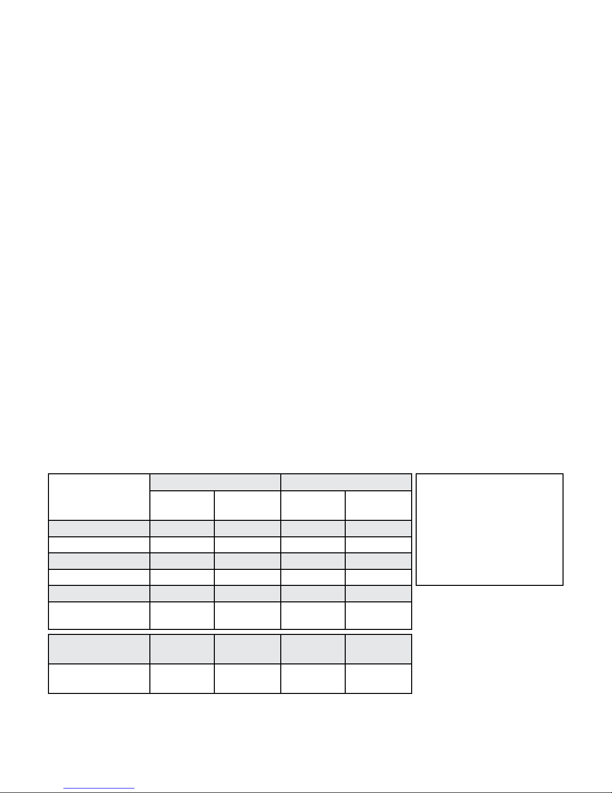
GAS AND ELECTRICAL SPECIFICATIONS
Input Rate Manifold Pressure Electrical Requirements
Models
MB42, SD448, SD1048
MB60, SD660, SD1060
SD236
SD248
SD260
MB866, SD866,
SD10866
WF42
WF60
NATURAL
GAS
95,000 90,000 4.5 IN. WC 11 IN. WC Volts 120VAC
115,000 115,000 4.5 IN. WC 11 IN. WC Frequency 60Hz
50,000 50,000 4.5 IN. WC 11 IN. WC 0.9 AMPS Phase 1
65,000 65,000 4.5 IN. WC 11 IN. WC
80,000 80,000 4.5 IN. WC 11 IN. WC
115,000 115,000 4.5 IN. WC 11 IN. WC
135,000 135,000
155,000 155,000
PROPANE
GAS
NATURAL
GAS
4.5 main
3.5 side
4.5 main
3.5 side
PROPANE
GAS
11 main
10 side
11 main
10 side
(MB Models Only)
Page 5

DELIVERY
Marsal & Sons, Inc. cannot assume responsibility for loss or damage suered in transit. The
carrier assumed full responsibility for delivery in good order when the shipment was accepted.
We are, however, prepared to assist you if ling a claim is necessary.
OVEN LOCATION
The oven should be installed in a location in which the facilities for ventilation permit satisfactor y
combustion of gas and proper venting. The oven should be located so as not to interfere with
proper circulation of air within the conned space. In buildings where normal inltration does
not provide the necessary air, outside air should be introduced.
It is essential that an adequate air supply to the oven be maintained to provide a sucient
ow of combustion and ventilation air.
•
Place the oven in an area that is free of drafts.
•
Do not place the oven on a curb base or seal to a wall. This will restrict the ow of air and
3
prevent proper ventilation. Pilot outages or yellow, oating ames on the main burners
are indicative of a lack of secondary air.
Before making any utility connections to this oven, check the rating plate to be sure the oven
specications are compatible with the gas and electrical services supplied for the oven. The
rating plate is located on the inside of the control door.
ADJUSTMENTS ASSOCIATED WITH INITIAL INSTALLATION
Each oven, and its component parts, have been thoroughly tested and inspected prior to
shipment. However, it is often necessary to further test or adjust the oven as part of a normal
and proper installation. These adjustments are the responsibility of the installer, or dealer.
Since these adjustements are not considered defects in material or workmanship, they are not
convered by the Original Equipment Warranty. They include, but are not limited to:
•
calibration of the thermostat
•
adjustment of the doors
•
burner adjustments
•
leveling
•
testing of gas pressure
•
tightening of fasteners
No installation should be considered complete without proper inspection, and if necessary,
adjustment by qualied installation or service personnel.
Page 6

For all oven models:
1.
Place the oven base in the nal location.
2.
Level the base from left to right and front to back by adjusting the legs in each corner.
3.
Place the oven body on top of the oven base making sure that the front and the front
corners are even between the base and the body.
4.
Install the two 1/4 x 20 x 1” bolts through the front of the base into the front of the
body from underneath the base. Next, align the back corners of the body and the base
together and install the other two 1/4 x 20 x 1” bolts through the back of the base and
the back of the body.
4
ASSEMBLY INSTRUCTIONS
5.
For stackable units, place the top oven on the bottom oven and align their front and
sides. The weight of the unit will keep it in place.
6.
Connect a gas line to the back of each oven and follow all local gas codes in connecting
to the gas supply.
7.
Plug in the electric plug for the light to an electric power supply. (For MB Ovens Only)
On the WF Ovens the power supply is for the electronic ignition.
8.
Connect the exhaust system to the ue of the oven.
NOTE: FOLLOW ALL LOCAL FIRE AND SAFETY CODES FOR VENTING AN OVEN. IF THE
OVEN IS BEING INSTALLED UNDER A CANOPY HOOD, THE 6” X 14” STAINLESS STEEL FLUE
VENT MUST BE INSTALLED. A CANOPY IS RECOMMENDED EVEN WHEN DIRECT VENTED.
9.
The base should be sealed to the oor using a NSF approved sealant.
10.
On the WF Ovens the stainless steel shelf is installed AFTER the cooking surface is
installed and cured
Page 7

VENTILATION
Local codes and conditions vary greatly from one area to another and must be complied with. The
following are the minimum requirements for good ventilation. Please remember that these are
general recommendations or guidelines and you may have a special condition or problem that will
require the services of a ventilation engineer or specialist.
5
Proper ventilation is the oven owner’s responsibility.
Improper ventilation
will inhibit oven performance, such as the pilot going out or the burning of the bottom
of pies.
Marsal & Sons, Inc. cannot assume responsibility for loss or damage suered as a result
of improper installation.
WARNING: Failure to properly vent the oven can be hazardous to the health of the
operator and may result in operational problems, unsatisfactory baking and possible
damage to the equipment.
Damage sustained as a direct result of improper ventilation will not be covered by
the Manufacturer’s warranty.
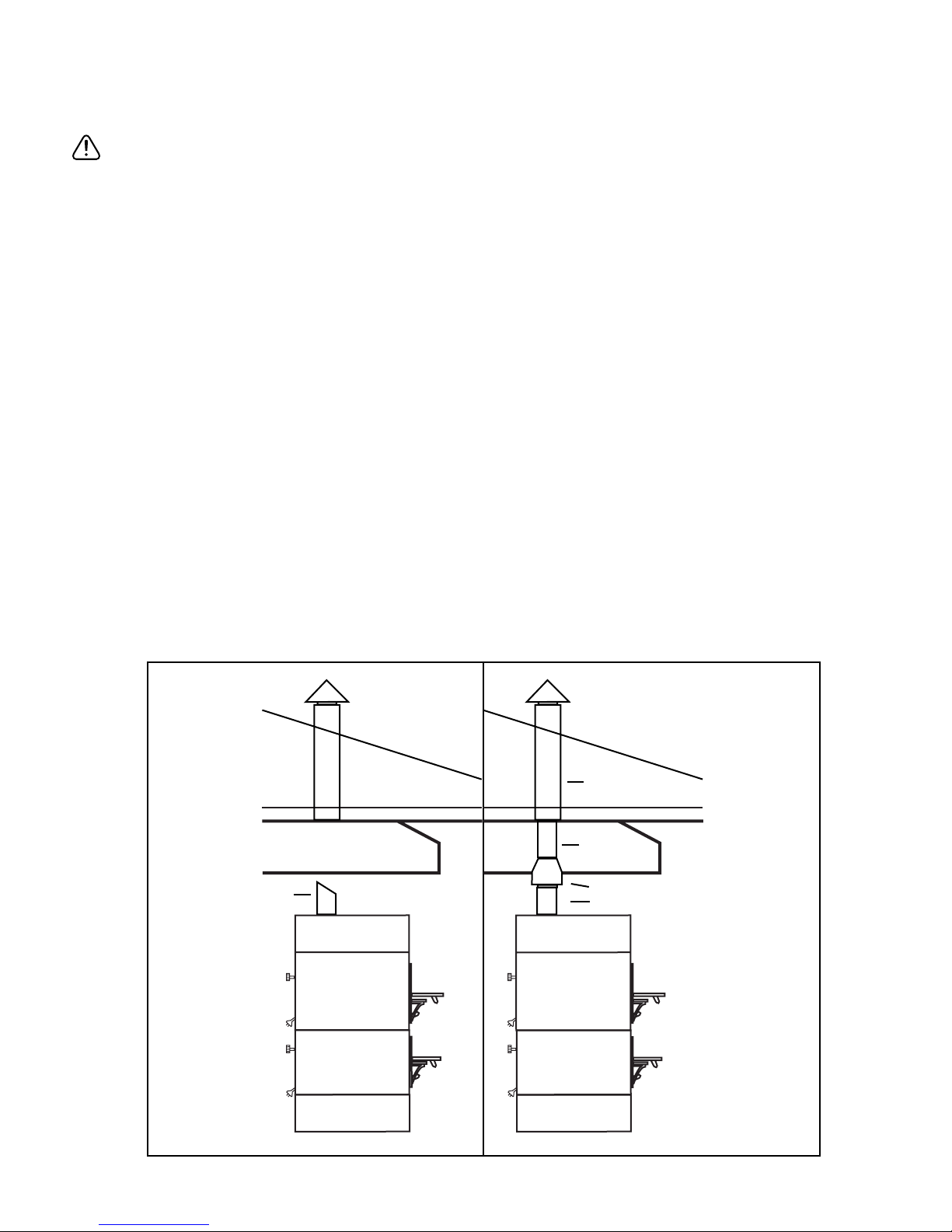
CANOPY METHOD
The ideal method of venting a gas oven is through the use of a properly designed ventilation hood
which extends 10” - 12” in front of the oven. The short stainless steel ue that is supplied with the
oven must be installed. Place the ue over the collar that is located on the top of the oven and
press down until it is rmly locked in place. The angle should face forward and always away from
any lters. A strong exhaust fan will create a vacuum in the room. For an exhaust system to work
properly, replacement air must be introduced into the room.
The hood should be sized to completely cover the equipment plus an overhang of at least
6” (15 cm) on all sides not adjacent to a wall and 10”-12” (25.4 - 30.4 cm) in front of the oven.
The distance from the oor to the lower edge of the hood should not exceed 7’ (2.1 m).
The capacity of the hood should be sized appropriately with provisions for an adequate
supply of make up air.
DIRECT CONNECTION METHOD
An unrestricted vent pipe that provides exit air at the oven of a minimum of 55 CFM per oven must
be provided for the vent pipe at the top of the oven. The vent pipe should be a minimum of 6” in
diameter. A draft diverter (or draft hood) must be installed for a direct vent connection system
in order to work properly. No more than two 90° elbows should ever be used in a direct vent
connection and all horizontal runs must have at least a 1” per foot pitch.
ANY horizontal run of vent pipe must have a pitch of at least 1” per foot.
Page 8
DIRECT CONNECTION METHOD (continued)
WARNING: It is essential that the direct ue be installed as follows. Incorrect
installation will result in unsatisfactory baking, oven damage, and pilot outages.
The ue must be class B or better. The height of the ue should rise 6-8 ft (2-2.5 m) above the
roof of the building or any proximate structure. The ue should be capped with a UL Listed
type vent cap to isolate the unit from external environmental conditions.
The direct vent cannot replace air consumed and vented by the oven. Provisions must be made
to supply the room with sucient make-up air. Total make-up air requirements for each oven
section should be approximately 30 CFM per section. To increase the supply air entering the
room, a ventilation expert should be consulted.
INSTALLING THE DRAFT HOOD
Ovens ordered for direct venting are supplied with a draft hood. Install the draft hood as
follows:
6
1.
Place the draft hood over the ue connector.
2.
Install the rest of the venting system to the draft hood (draft diverter).
CANOPY METHOD
INSULATED
FLUE VENT
6” Flue
STAINLESS STEEL VENT
(INCLUDED)
DRAFT DIVERTER
DIRECT CONNECTION
METHOD
Page 9
VENTING PROBLEMS
If the venting of any deck oven is either restricted or forced in any way the baking characteristics
of the oven will be adversely aected.
Examples of restricted venting include:
•
use of tees and elbows
•
long horizontal runs without the proper pitch of 1” per foot
Insucient make-up air can cause heated air and combustibles to remain in the oven shortening
the life of the components.
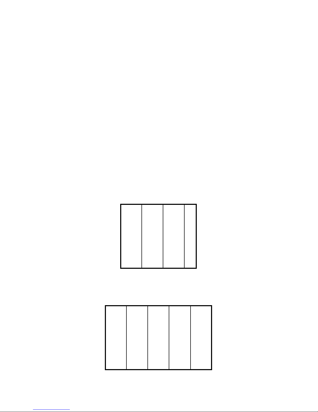
INSTRUCTIONS FOR INSTALLING BRICKS
The following instructions are model specic.
1.
Start by installing the brick used for the baking deck. These bricks are 2” Thick and must
be installed ROUGH SIDE UP. Push bricks together to eliminate any space.
7
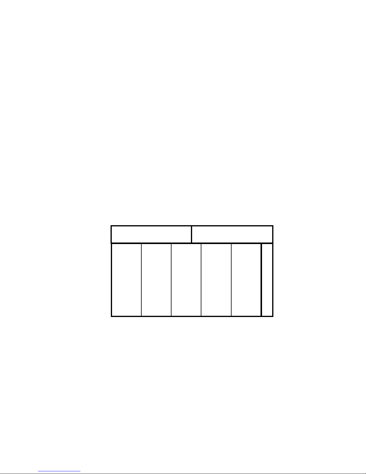
MB 42 Place the (3) 12” x 36” bricks and the (1) 6” x 36” brick on the sheet metal of the oven
deck. The 6” x 36” brick must be placed on the right side of the deck oven as shown
below.
12”12” 12”6”
FRONT OF OVEN
MB 60
SD 660
SD 1060
Place the (5) 12” x 36” bricks on the sheet metal of the oven deck as shown below.
12”12” 12” 12”12”
FRONT OF OVEN
Page 10
8
MB 866
SD 866
SD 1086
INSTRUCTIONS FOR INSTALLING BRICKS
(continued)
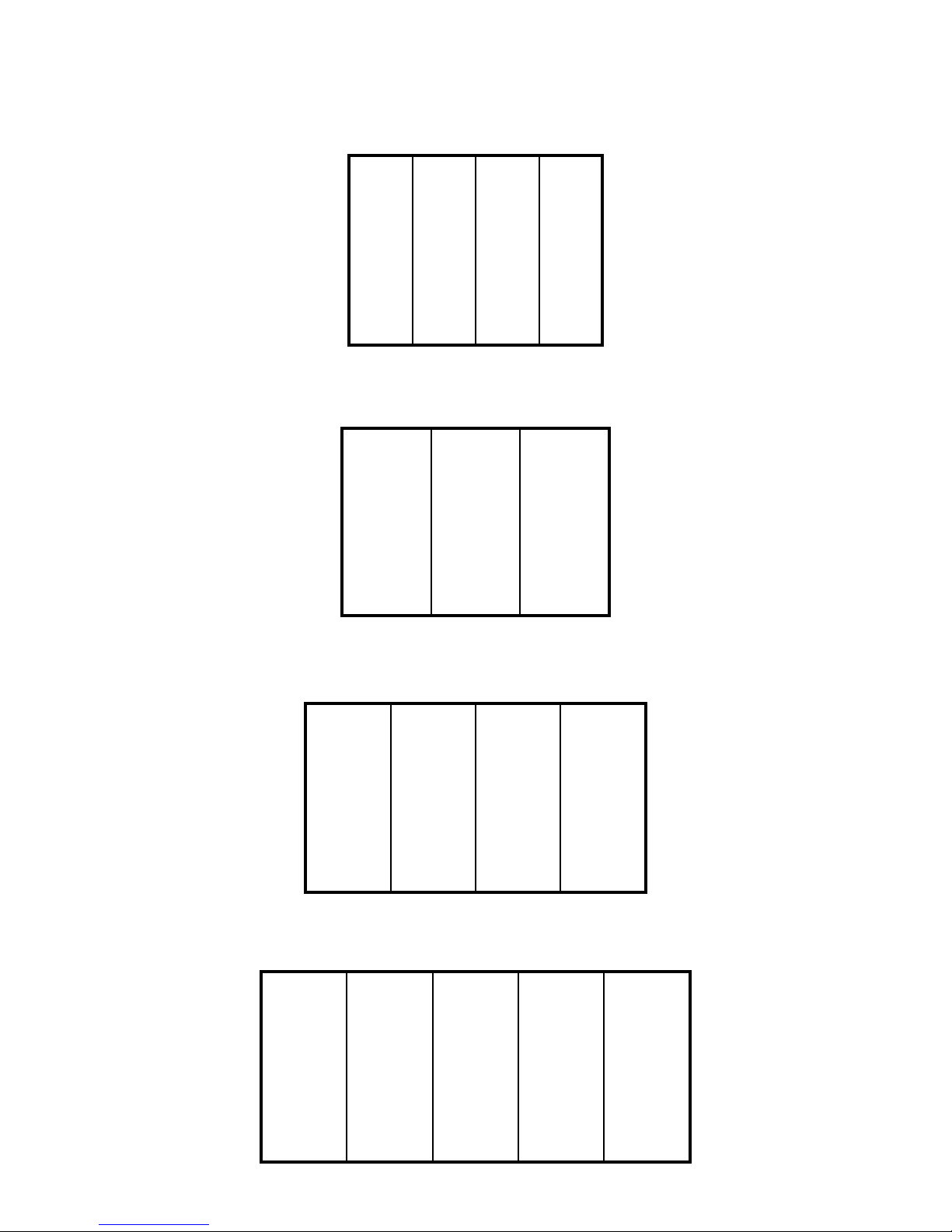
1. Place the (2) 8” x 33” bricks across the back rst.
2. Place the (5) 12” x 36” bricks on the sheet metal of the oven deck as shown below.
3. The (1) 6” x 36” brick must go on the right side as shown below.
8” x 33”
12”12” 12” 12”12”
FRONT OF OVEN
8” x 33”
6”
Page 11
INSTRUCTIONS FOR INSTALLING BRICKS
(continued)
9
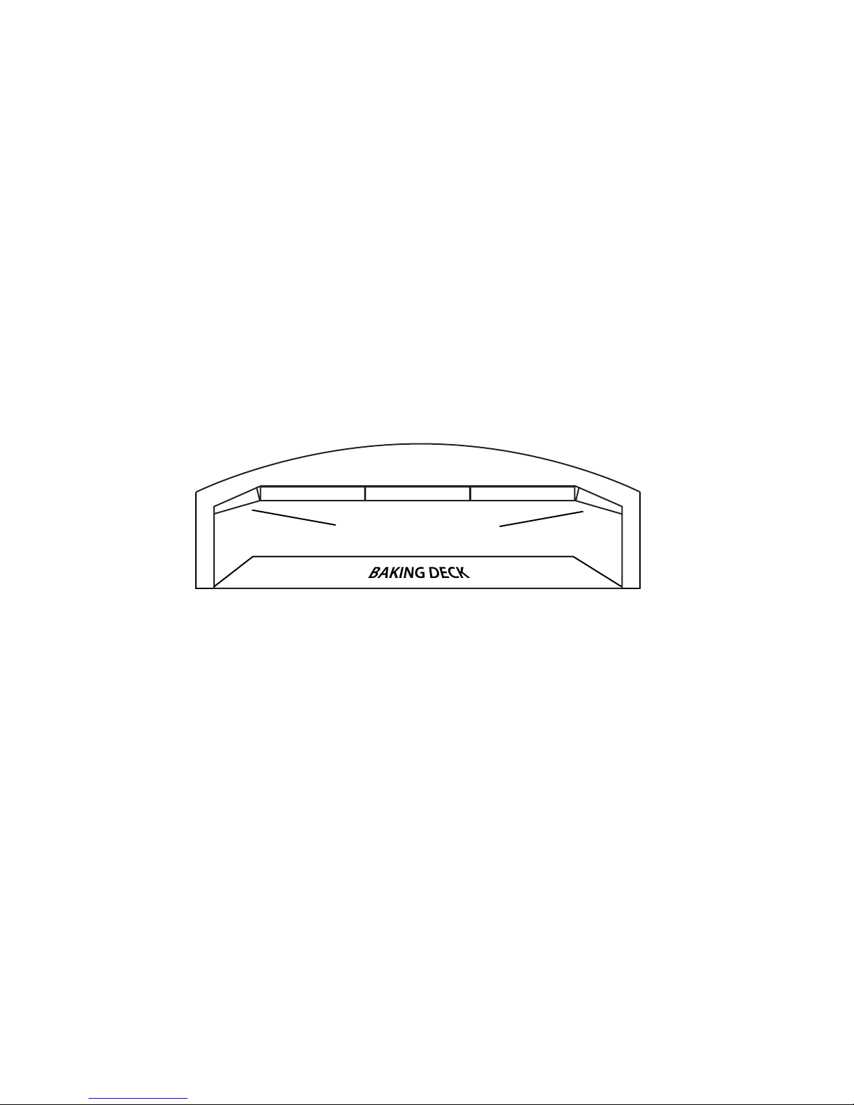
SD 448
Place the (4) 12” x 36” bricks on the sheet metal of the oven deck as shown below.
SD1048
12”12” 12”12”
FRONT OF OVEN
SD 236 Place the (3) 12” x 24” bricks on the sheet metal of the oven deck as shown below.
12”12” 12”
FRONT OF OVEN
SD 248 Place the (4) 12” x 24” bricks on the sheet metal of the oven deck as shown below.
12”12” 12” 12”
FRONT OF OVEN
SD 260 Place the (5) 12” x 24” bricks on the sheet metal of the oven deck as shown below.
12”12” 12” 12”12”
FRONT OF OVEN
Page 12
INSTRUCTIONS FOR INSTALLING BRICKS
(continued)
MB SERIES OVENS ONLY.
2.
Install the brick in the dome. These bricks are 1 ½” thick and must be installed as follows:
10
MB 42 1. Slide (5) 9
2. Slide (5) 12” x 6” bricks on each of the 12
MB 60 1. Slide (5) 12
MB 866
1. Slide (4) 2” x 12” bricks first in the 12 ½” tracks (1) per track
2. Slide (2) 2” x 8 ¼” bricks first in the 8 ½” tracks (1) per track
3. Slide (6) 12” x 6” bricks on each of the
4. Slide (6) 12” x 8 ¼” bricks on the 8 ½” tracks located in the middle of the chamber
½” x 6” bricks on each of the 10” brick support tracks in side the top of the oven.
½” tracks.
” x 6” bricks on each of the brick support tracks.
12
½” tracks.
5 Bricks On Each Track
(MB42 & MB60)
CURING THE OVEN DECK
1.
Sweep o all the debris from the brick deck surface.
2.
Cure the oven deck slowly by preheating the stones with the pilot burner on for 1 hour.
Then gradually increase the temperature 100° F per hour from 300° - 600° F is reached.
NOTE: WHEN LIGHTING THE OVEN FOR THE FIRST TIME, AS THE TEMPERATURE INCREASES,
SMOKE WILL OCCUR FROM THE OVEN. BE SURE TO LEAVE THE DOORS CLOSED, VENT OPEN,
AND TO HAVE THE EXHAUST FAN ON THE HOOD TURNED TO ON.
© Marsal & Sons, Inc. 175 E. Homan Ave. Lindenhurst, NY 11757 (631) 226-6688 www.marsalsons.com
Page 13

OPERATING MANUAL
STARTING THE OVEN
1.
Purge all air out of the gas line. (Initial startup)
2.
Open the control door and open the burner door at the bottom of the oven.
3. Hold the red button in and manually light the pilot (this is seen through the opening
on the left, inside the burner area).
4. Hold the red button in until the probe in front of the pilot gets hot. (approximately
30 seconds) Then release the red button. Pilot should stay lit - if not, try again.
5. Adjust the oven temperature to the desired amount (usually between 500°-600° F
for pizza). The main burners will turn on.
6. Close the control and burner doors.
NOTE: The oven’s cooking surface is for pizza and bread only. All other products must be placed
in pans.
11
• Set the bypass on the thermostat by following the instructions in the service
manual.
• Check calibration and adjust if necessary by following service manual.
Setting the bypass and calibrations and other adjustments are not covered under warranty
and are the responsibility of the owner or the dealer who sold or installed the appliance.
If the oven is supplied on casters and is connected to the supply piping by means of a
connector for movable appliances, be aware that a restraint must be on the appliance and,
if disconnection of the restraint is necessary, you must reconnect this restraint after the
appliance has been returned to its originally installed position.
OVEN CONTROL
PREHEATING OVEN
On initial startup, preheat the oven to 600° F (315° C) over a period of four hours in increments
of 100° F (55° C) starting at 300° F (149° C).
TURNING OVEN OFF
You can shut the main burners o and leave the pilot on by turning the green valve, located
between the safety pilot valve and the thermostat, clockwise to the 3 o’clock position.
Extinguish the pilot ame by blowing out the pilot ame.
A 5 minute complete shuto period is necessary before the oven can be relighted.
Shut o side burner by turning the toggle switch to OFF position (WF only)
Page 14

MAINTENANCE
OVEN EXTERIOR
The stainless steel surface should be cleaned when cool using a mild soap and warm water
solution on a sponge or a clean cloth. On WF Ovens, clean the glass only when the oven is cool.
OVEN INTERIOR
The inside metal surfaces should be cleaned with a mild detergent and a damp cloth when
necessary. The brick surface should be brushed clean and then a wet cloth draped over the
brush should be run over the surface while the oven is still hot.
NOTE: The burner venturi must be checked and kept clean. The area around the air shutter
must stay about 1/8” - 3/16” open and free of any dust.
CLEANING THE OVEN
On the stainless steel front the deposits of baked splatter may be removed with any nontoxic
industrial stainless steel cleaner. Heat tint and heavy discoloration may be removed with any
non-toxic commercial oven cleaner.
12
1.
Apply cleaners when the oven is cold, and always rub with the grain of the metal.
Clean the aluminized interior portion of the oven with a mild detergent. DO NOT use caustic
solutions such as ammonia, lye or soda ash. DO NOT use domestic oven cleaners. Any of these
products will damage the aluminum coating.
DAILY CLEANING
•
Clean brick surfaces using a deck scraper and brush. A wet towel draped over the brush
should be run over the brick surface while the baking chamber is still hot.
WEEKLY CLEANING
•
Brush out the combustion compartment behind the burner door.
6 MONTH CLEANING
•
Clean secondary air ducts and air entry ports.
•
Clean the area around the air shutter so that it stays 1/8” - 3/16” open and free of dust.
CAUTION: Disconnect the power supply on MB Ovens before Cleaning or Servicing.
If maintenance or repairs are required, contact the factory, the factory representative or a local
Marsal service company.
© Marsal & Sons, Inc. 175 E. Homan Ave. Lindenhurst, NY 11757 (631) 226-6688 www.marsalsons.com
Page 15

WF MODELS
OPERATION
•
To turn on the side burner, you must rst ip the toggle switch (located in the control
compartment) up to the ON position. This will turn on the electronic ignition and light
the pilot
•
Align the red handle valve located on the right side of the control compartment with
the gas line. This will put the side burner at full ame.
• Start with the thermostat set at “5” and the side burner ame on FULL.
• To shut o the side burner just ip the toggle switch down to the OFF position.
CONTROLLING TOP AND BOTTOM HEAT
13
•
To get the most top heat, the side burner should be on FULL. You can decrease the
amount of top heat by partially closing the valve for the side burner.
•
Adjust the bottom heat by raising or lowering the thermostat knob.
• Use the thermometer on the right side of the oven to determine the top heat on the
ame side of the baking chamber.
• **** The heat on the right side of the oven is higher than on the left side. Any part
of the product being cooked that is facing the ames will cook faster and therefore
the products must be spun and watched carefully.
INSTALLATION OF S/S FRONT SHELF AND FRONT HOOD
•
Install the front stainless steel shelf after the cooking surface is installed and cured. Use
the four tec screws provided to secure the shelf to the body of the oven (Note: the shelf
will close the gap between the cooking surface and the front of the baking chamber.
•
If the hood in the front has been removed then reattach by sliding the hood over and
down the screws located in the front of the oven along side the ue.
©2012 Marsal & Sons, Inc. 175 E. Homan Ave. Lindenhurst, NY 11757 (631) 226-6688 www.marsalsons.com
 Loading...