

Page 1
Installation and Operation manual
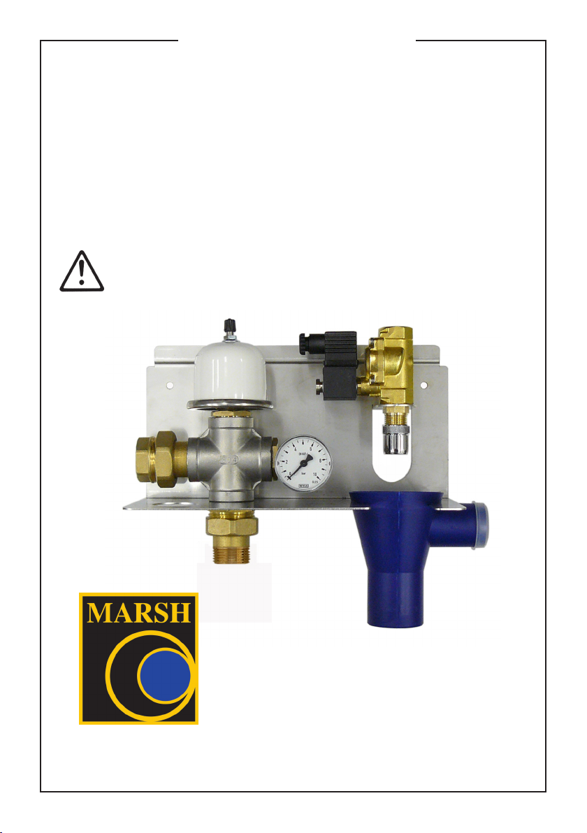
Rain Cell
- This document must be read prior to installation!
- Follow all safety notes!
- Keep in a safe place for future use!
This installation and operation manual contains important notes and warnings.
Please read the installation manual in any case prior to electrical connection
and start-up.
We reserve the right to make technical modifications. 01.06.2015
Page 1
Page 2
1.1 Preface
Please read and follow this operating manual in order to achieve a long service life of the
unit. Please follow the installation manual when installing and commissioning the unit. The
product has been tested at our works. This means that it has been delivered free from
defects. However, in case of a failure during operation, please see chapter 2.6.
1.2 Warranty (excerpt)
The warranty period is 24 months from the date of purchase of the product.
Within the guarantee period, we will eliminate functional faults free of charge which are
due to manufacture or material defects. These are failures which occur despite proper
connection, proper handling and due consideration given to the operating and installation
manual.
„Please see the valid warranty regulations in our current general Terms & Conditions“.
1.3 General notes
• This unit has to be installed in accordance with the technical guidelines
such e.g. BS EN 1717!
• The user is responsible for the following actions:
- of proper installation
- To avoid risks due to improper operation.
• The unit has been designed solely for use:
- at 230 V, 50 Hz AC voltage,
- in rain water harvesting systems,
- for mains water supply to the storage tank,
- up to a water temperature of 35° C,
- In the vicinity of residential, trade and industrial areas as well as small
sized companies.
• The following kinds of operation are prohibited::
- the pumping of polluted or contaminated sewage water,
- the pumping of water with acid content, as well as generally corrosive
liquids,
- the pumping of water with a temperature higher than 35° C.
- the pumping of flammable and / or explosive media,
- Installation in frost-prone environment
- the operation in a dry state.
Page 2
Page 3
1.4 Protective measures
• The user must strictly observe the accident prevention measures of
the respective country.
• The corresponding VDE (Association for Electrical, Electronic &
Information Technologies), national and EVU (European Association for
Accident Research and Analysis) regulations in the respective valid
version must be observed with respect to the electric installation. The
electric installation must be carried out by certified technicians, taking
VDE 0100 or similar national regulation into account.
• It is recommended during commissioning of the submersible pump,
that persons not be in the water (rain storage container) and that this
work not be done with wet hands.
• The power supply to the submersible pump is to be disconnected during
repair work; to do this the plug should be removed from the electric
socket.
• Any kind of repair, installation, or modification work done on the
submersible pump and any of its components which have live parts can
cause serious injury to persons, and even fatalities.
• At the location of the installation the source of electricity should be fused
with an earth leakage circuit breaker (30 mA).
The user may not tamper on their own initiative with any parts or systems
in any way which is not called for in the operating and installation
instructions.
No financial liability will be accepted resulting from improper installation or
operation.
1.5 Scope of supply
• Multistage submersible pump
• ¾“ solenoid valve with stainless steel bracket, backup and funnel
• Float switch 20m
• Connection box
• Installation and Operation manual
1.6 Product description
The Rain Cell controller is central to your rainwater harvesting system. The submersible
pump in the tank controls the water flow from the storage tank to the designated outlets
for the consumer. The automatic pump controls the volume and pressure that is required.
The submersible pump switches on automatically when there is a reduction of pressure,
(ie one of the outlets is open), and once the outlet is closed again the increase of
pressure automatically turns the pump off. The submersible pump also has dry-run
protection which prevents the pump running should there be no water available. The
solenoid valve mounted in the building will fill the storage tank (according to DIN EN 1717)
with mains water automatically when required, this ensures that there is always some
water in the storage tank at all times.
Page 3
Page 4
1.7 Mounting of the unit
Prior to installing the unit, make sure to observe the back pressure level1) when connecting
the outgoing drainage at later time, refer to chapter 1.9 connecting overflow.
1)
Back pressure level:
Level, can flow back up to what an overloaded outgoing drainage system. Usually
corresponds to the respective street level. Check with your local building authority.
Mount the stainless steel holder of the unit:
• In a dry room, free of frost, e.g. utility room.
• Above the maximum water level of the rainwater storage tank (see fig. 1).
- Ensure that the pipework from the funnel to the rainwater tank is at least a constant
gradient of 1% and there are no vertical rises.
• On a level floor (to avoid distortion within the unit).
• In a room with drainage point in the floor.
• Vertical (to prevent malfunctions).
Higher than the maximum water level in
Fig. 1
the storage tank including gradient up line.
Higher than the back pressure level
1)
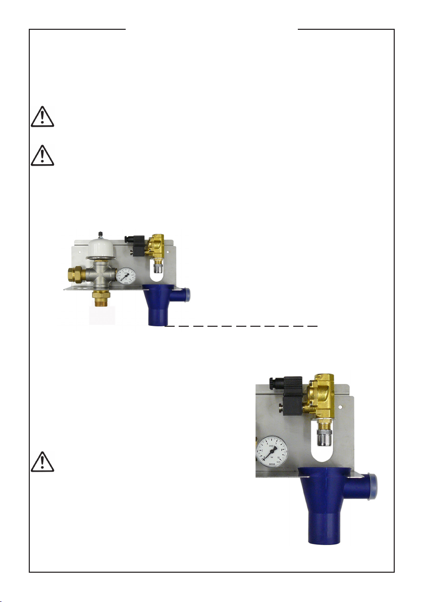
1.8 Mounting of the solenoid valve
• Ensure the funnel is placed in the metal
bracket with the overflow facing outwards,
then rotate the funnel 90 degrees so that the
overflow is under the metal bracket. This
will ensure the air gap cannot be breached.
- If not go out following the DIN EN 1717!
• Solenoid valve to align the holder and fasten
tightly from below with the ¾“-½“nipple.
- Pay attention please to the flow direction
(down arrow)!
• Aerator screws tight on the nipple
- Pay attention please to the rubber seal!
Page 4
Fig. 2
Page 5

1.9 Connection of mains water refilling pipe
Ensure that pipe work from the bottom of the funnel to the rainwater tank is connected
so that mains water can flow freely.
Recommendation:
For this, use a plastic pipe DN 50, which is run through an empty tube
• The refilling pipe by means of DN 50 pipe connects to the bottom of the funnel and into
the storage tank.
• Make sure that there is at least a 50cm drop in the mains water pipe from the bottom of
the funnel to ensure that the water can flow freely and not backup towards the funnel.
• The refilling pipe must have be a steady slope to the storage tank.
• The DN 50 refilling pipe must be inflow above the maximum water level in
the collection container into the feed tube of the calmed inlet.
1.10 Connection of emergency overflow
A 40mm pipe has to be connected to overflows of the funnel. The overflow has to be
connected to the outgoing drainage or to the pumping station
• Make sure that there is at least a 50cm drop in the overflow pipe from the side outlet of
the funnel to ensure that the water can flow freely and not backup towards the funnel.
- That way the water can drain properly.
• A siphon trap can be installed in the overflow pipework to avoid sewer gases or
smells from entering the building.
2.1 Submersible pump
• Position the supply pump in a stable way
on the base of the storage tank, see fig. 3.
• Attach the rope on the frame of the
submersible pump.
• Securely fasten the other end of the rope,
slightly taut, with the screw to the upper
area of the storage tank.
- This is to prevent unintentional tipping over
of the supply pump.
- If need be this can also be used to take the
supply pump out of the storage tank.
Fig. 3
Page 5
Page 6

2.2 Pressure pipe
If dirt gets into the pressure pipe during the installation, the pipe has to
be flushed before connection to the unit. Ensure that the pressure pipe
from the pump to the control unit is as straight as possible. This will make
sure that there is no loss of pressure.
Note!
We recommend connecting the pressure pipe via braided hoses and a shut off valve.
This will:
- eliminate vibration and sound transmissions
- eliminate installation inaccuracies
- enable shutting off the pressure pipe at any time
- help to eliminate malfunctions with only a small effort.
• Use a 1" pressure pipes (minimum inside diameter 25mm).
• The pressure pipe should be installed as direct as possible.
• Connect the pressure pipe leak-tight and tightly with the outlet of the submersible
pump in the storage tank.
• Connect the pressure pipe leak-tight and
tightly with the pressure inlet of the unit,
see fig 4.
• Connect the pressure outlet of the unit
with the existing pressure pipe in the
building.
• The first pipe clip has to be installed with
a maximum distance of 10-15 cm from
the unit
- This avoids transmission of vibrations into
the pressure pipe.
Pressure outlet
Fig. 4
Pressure inlet
• Lay the electrical cable of the supply pump up to the connection area in house.
- The electrical cable or the pressure pipe may not be broken or laid over sharp edges.
• In order to avoid a damage of the main, this is to be fastened with the cable straps in
regular intervals to the pressure pipe, see fig. 3.
Do not bury the electrical cable without any protection.
Recommendation:
Use a 110 mm duct to connect the storage tank and the building for electrical cable and the
pressure pipe. The duct has to be sufficiently sealed to prevent water entering the
house.
Page 6
Page 7

2.3 Connection of mains water
The solenoid valve is designed for a pressure of 3.0 bar up to a maximum of
4.0 bar. If the pressure in the potable water pipe is above 4.0 bar a pressure
reducing valve has to be installed. Higher pressure in the potable water pipe
may an overflow of the funnel. We strongly recommend installing a filter in
the mains water pipe to avoid pollution of the solenoid valve. The filter should
have a pore size of 110 microns (0.11mm). If the hardness of the drinking
water exceeds 20, a reciprocal decalcification can be installed.
Before connecting the mains water pipe to the solenoid valve, the mains
water pipe has to be flushed.
Note!
We recommend connecting the solenoid valve via braided hoses and a shut off valve to
the mains water pipe. This will:
- eliminate vibration and sound transmissions
- eliminate installation inaccuracies
- enable shutting off the mains water pipes at any time
- help to eliminate malfunctions with only a small effort
- The mains water pipe can be shut off in the case of a longer absence.
• Connect the mains water pipe tightly to the connection of the solenoid valve.
• The first pipe clip has to be installed with a maximum distance of 10-15 cm from the unit
- This avoids transmission of vibrations into the mains water pipe, when the solenoid
valve closes.
2.4 Float switch
The cable of the float switch has to be fixed in the turret of the storage tank.
The distance between the lower side of the float switch and bottom of tank
has to be 12cm, see fig.5.
• The borehole for the cable clip of the float
switch has to be 8 mm. Drill the hole and insert
the dowel in the borehole.
• The cable clip has to be installed above the
maximum water level of the tank.
• The cable of the float switch has to be put in
the cable clip. The cable clip has to be fixed
slightly with enclosed screw and washer.
• Adjust the distance between the lower side
of float switch and the bottom of the tank to 12
cm, see fig. 5.
• Fix the cable clip tightly.
The floater switch should not collide with any objects in the tank. (e.g. wall of
the tank or calmed inlet). Such a collision may cause malfunction of the system.
Weight
Floater
12 cm
Bottom of tank
Fig. 5
Page 7
Page 8

• Move the cable of the float switch to the unit.
Cable Extension
The cable (H07 RN-F 3x1mm²) of the float switch can be extended.
- The cable extension has to be water tight.
- Only be held by a qualified electrician.
• Connecting the float switch as shown in Fig. 6
Supply line with switch
230V / 50Hz
Float switch
BlueBrown
Fig. 6
Submersible pump
Solenoid valve
Green/
Yellow
2.5 Commissioning
- Dirt is not allowed to be in the unit and in the pipes connected to the unit!
- Pump and feeding must be installed properly!
- All water connections and screw joints have to be watertight!
- The storage tank must be filled with water so far that the submersible
pump is completely covered, otherwise top up storage tank!
- Make sure that the unit is disconnected from the power supply.
• Open all valves for the potable and pressure water lines.
• Open appliances (e.g. WC, taps).
• Connect the mains of the connection box (3 x 1.5 mm²) to the power supply in
accordance with the above named regulations.
- If the storage tank is empty the solenoid valve will fill up the storage tank with
potable water.
- The submersible pump will start.
Page 8
Page 9

• Close applications, if water flows continuously without air interruptions.
- The pump builds up maximum pressure and switches of after approximately 10 seconds.
• The system can be operated
or
If any malfunction occurred please refer to chapter 2.6.
2.6 Elimination of faults
Proceed as follows:
1. Isolate the unit from the mains by the main switch.
2. Eliminate the fault; refer to the following possible faults under: What to do if....
3. Switch on the mains again.
What to do if....
The submersible pump does not starts?
The mains are not correct installed, or the plug of the pump/ pump control is not plug in?
Check the mains and plug the pump/ pump control in the socket of the connection box.
The submersible pump has run dry and turned off?
Check the storage tank and the float switch.
Check the pressure line and submersible pump and fill up if necessary the storage tank.
The pump does not build up pressure?
In the storage tank is not enough water?
Check the solenoid valve and fill up if necessary the storage tank.
The pump is dirty?
Contact your contract partner / distributor.
The solenoid valve does not stops automatically?
The solenoid valve is dirty?
The solenoid valve needs to be cleaned by suitable qualified person or replaced.
Float switch in the storage tank does not switch correctly?
Installed the float switch correctly, see chapter 2.4.
If the failures could not be eliminated, please contact Marsh Industries.
Page 9
Page 10

2.7 Important notes
General information
This product has been developed in accordance with the latest technologies and is
subject to continuous quality checks. This manual contains important notes on how to
operate the system safely, properly and economically, and should help the user to become
familiar with the unit and to get the best use from the intended application. Please
follow these important notes in order to ensure the reliability and long service life of the
system components and to avoid hazardous risks. The operating and installation manuals
do not take local by-laws or planning constraints into account, which must be met by the
user.
Please refer to the name plate on the unit for the model type and number, important
operating data and the manufacturer’s serial number. This information must be quoted
in all correspondence regarding technical assistance and particularly when ordering
spare parts.
The installation and operating manuals should be left available at a convenient place
close to the unit.
Personal training and qualification
The personnel involved in the operation, maintenance, inspection and assembly must
be suitably qualified for this work. The owner must regulate the responsibilities,
competence and supervision of the personnel. If the personnel are not qualified sufficiently,
they must be trained and instructed accordingly. This can be done, if necessary, by the
manufacturer/ supplier on behalf of the owner of the unit. In addition, the owner should
ensure that the personnel understand the complete contents of the installation and
operating manuals.
Risks in case of non-observance of safety notes
No claims for damage will be accepted if the safety guidelines are not followed. Nonobservance may result in the following risks: Failure of important functions. Failure of
specified methods for maintenance and service. Hazards to people by electrical and
mechanical effects.
Safety awareness during work
The safety notes given in manuals, the existing health and safety regulations, and
operating and safety regulations of the owner (if any), must all are met.
Safety notes for the owner/user
Danger due to electrical power must be prevented (for details please refer to the
country specific regulation of the authorities).
Page 10
Page 11

2.7 Important notes
Safety notes for assembly work, inspection and maintenance
It is the responsibility of the owner that any maintenance, inspection and assembly work
is carried out only by qualified specialists who are acquainted with the installation and
operating manual. All safeguards and protective features must be attached and/or put
into operation immediately on completion of work. Prior to re-commissioning, follow
the items given in section commissioning.
Unauthorized modification and fabrication of spare parts
No reconstruction or modification of the unit is allowed. Original spare parts and accessories
authorized by the manufacturer only, must be used for safety reasons. No liability will be
accepted for consequences resulting from the use of other unauthorized components.
Undue modes of operation
The safety of operation of the unit is assured only if the unit is used in accordance with the
purpose intended. The limit values specified in the data sheet must not be exceeded.
Transport, intermediate storage
When handling the unit do not hold or carry it by the electrical supply cable. Ensure also
that the unit is not dropped, and that all impacts are avoided during transportation. Store
the unit in a dry, cool and frost free room protected from sun radiation
Erecting / Assembly safety regulations
Your electrical systems must be in compliance with the general national regulations (IEC
364/VDE 0100), i.e. the sockets must be provided with earthing terminals. The electrical
mains for the connection of the unit must be provided with a residual current circuit
breaker in accordance with EN 60335-2-41. Please contact your specialist electrical
supplier, if necessary. When using an extension cable makes sure that its quality is in
compliance with the specification of original cable. Always unplug the mains plug prior
to mounting or demounting pipelines or carrying out other work at the unit.
Electrical installation safety regulations
The sockets must be provided with earthing terminals. The electrical mains must be provided
with a residual current circuit breaker in accordance with EN 60335-2-41. Please contact
your specialist electrical supplier, if necessary.
Electrical connection
Ensure that the unit is suitable for connection to the mains current according to the data
on the nameplate. The safety regulations for your electrical connection must be met in
all cases. It is then sufficient to connect the cable of the unit using a switched fused spur
outlet or fused plug via a normal switched socket outlet.
Maintenance and service / General Notes
Unplug the mains plug prior to any maintenance/service work. Cable extension and
opening of the unit must be done only by authorized specialists. No guarantee or other
liability claims will be accepted by the manufacturer if any part has been disassembled.
Re-assembly must be done only by authorized specialists.
Safety Norms
The unit complies with the norms EN ISO 12100 -1 / -2, EN 55014-1, EN 55014-2, EN
60204-1, DIN 1988 Part 4, DIN EN 1717.
Page 11
Page 12

2.8 Conformity statement
EC Conformity Statement
In the sense of EC Directive
Electro-magnetic compatibility 2004/108/EG
Low-voltage Directive 2006/95/EG
Machine Directive 2006/42/EG
This is to certify that the following unit – due to its design and type of construction –
meets the relevant basic requirements of the EC Directive.
Product designation: Rain Cell
Type designation: Rain Cell
Applied harmonized norms: EN ISO 12100 -1 / -2; EN 55014-1; EN 55014-2;
Applied national norms: DIN 1988 Part 4; BS EN 1717
The following operating conditions and environments of use shall be required.
The unit has been designed to control/regulate and operate a rainwater harvesting
system. The unit shall be installed in a dry room protected from frost. Operation in an
industrial environment, open-air installation and installation in wet cubicles shall not be
allowed. The operating manual and the installation manual shall be observed and followed.
EN 60204-1
01.06.2015
Date / manufacturer signature
SpinFlow GmbH
Wilberhofener Str. 2
51570 Windeck / Germany
T: +49 (0) 2292 / 929 42-0
F: +49 (0) 2292 / 929 42-22
Page 12
 Loading...