

OVEN SERVICE MANUAL
MB42, MB60, MB236, MB260, SD236, SD248, SD 260, SD448, SD660,
SD1048, SD1060, 4 Pie Combo, 6 Pie Combo
RETAIN THIS MANUAL FOR FUTURE REFERENCE
© Marsal & Sons, Inc. 175 E. Homan Ave. Lindenhurst, NY 11757 (631) 226-6688 www.marsalsons.com
TESTING OF COMPONENTS
AUTOMATIC SAFETY PILOT VALVE (TSII) #SV105
Pilot gas is supplied from the main valve inlet through a
drilled passageway to the pilot burner. Pushing the red reset
button temporarily allows gas to ow to the pilot burner for
ignition of the pilot burner ame. When the bulb heats to a
cherry red glow, the main valve opens to allow gas to ow
to the main burner. The red reset button is then released.
If the pilot burner ame fails and cannot be reactivated the
following test can be performed:
•
Pilot Burner Adjustment: Refer to section on Page 3
•
Clean Pilot burner’s limiting orice as follows:
1. Disconnect gas tubing at the pilot burner body.
2. Remove cup shaped orice from pilot burner
body.
3. Clean orice by blowing any foreign matter out
the orice hole. Take care not to enlarge orice
hole.
4. Replace components in reverse order. If the pilot
burner still does not operate or the main burner
comes with a low ame, or will not come at all,
replace the Automatic Safety Pilot Valve (TSII)
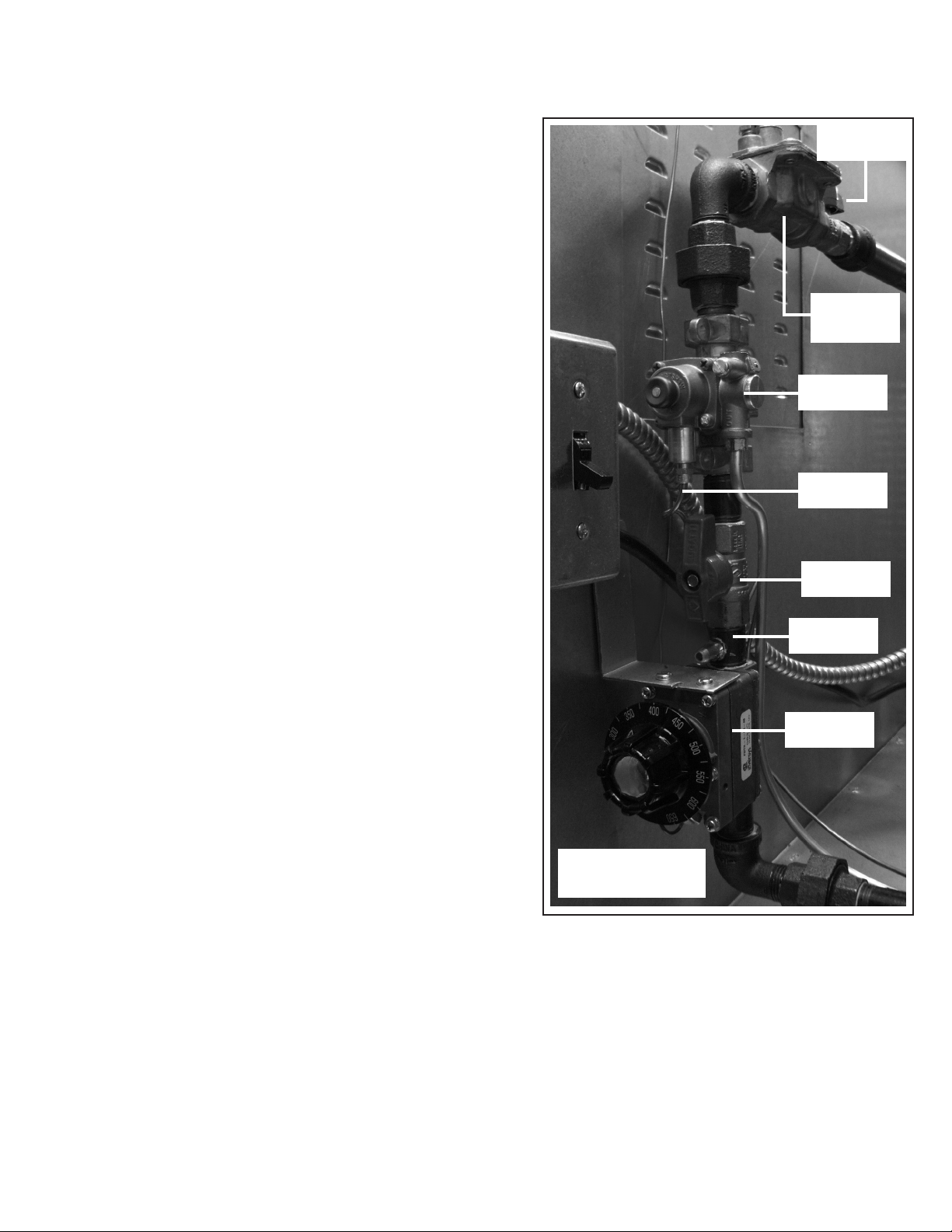
manual control
valve #M125
pressure
regulator
#RVL8-N (or) P
safety valve
#SV105
thermocouple
#TE48
manual control
valve #M125
pressure tap
MAIN MANUAL CONTROL VALVE #M125
thermostat
#G140
The main manual control valve is a simple bull valve. Due
to its simplicity, failures of this type of valve are practically
non-existent. For diculties associated with this control, it
would be best to replace the valve.
OVEN CONTROLS
(FIGURE 1)
THERMOSTAT FDTH #G140
For any suspected thermostat problems the following procedures should be reviewed in this manual:
•
Thermostat adjustment.
•
Bypass (Minimum Burner Flame) adjustment.
•
Thermostat calibration. Most thermostat failures will generally fall into one of the following three categories:
1. If thermostat is in a runaway condition and will not shut o at set temperature, replace the
thermostat.
2. If thermostat will not maintain calibration after adustment, replace thermostat.
3. If thermostat bulb or capillary are cut, bent, or unnecessarily attened, replace thermostat.
MAINTENANCE INSTRUCTIONS
ADJUSTMENTS
Many malfunctions attributed to defective material or faulty workmanship may be rectied by the adjustment of
pilot burners, main burners, or thermostats. It is therefore wise to attempt to correct operational diculties through
adjustment rather than the immediate replacement of parts.
Pilot Burner Adjustment #M111
A commonly diagonsed malfuction of the safety pilot valve is the pilot burner/ame sensing bulb relationship
resulting from:
•
Low gas pressure.
•
Clogged pilot burner orice from dirt and debris from unpurged gas lines.
•
Incorrect adjustment of pilot burner ame.
•
Flame sensing bulb not positioned in hottest part of pilot burner ame. Highest ame temperatures
occur at a point just above the outer ame cone.
To make this adjustment, proceed as follows:
1. Loosen screw that holds the safety pilot probe to the bracket and adjust the bulb so that it is in the ame
properly.
2.
Insert a small screwdriver just below the red button of the safety valve.
3. Turn adjusting screw until the size of ame is as desired.
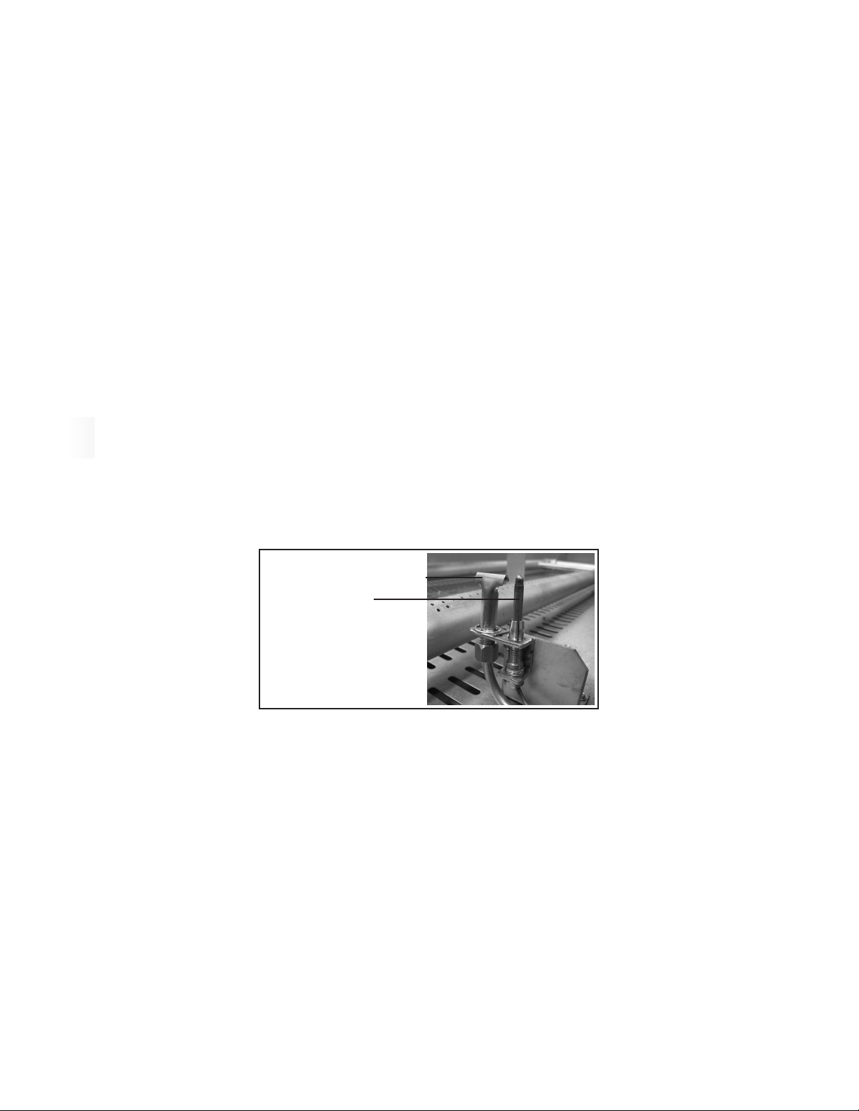
4. The ame must engulf the safety tip.
pilot hood
safety pilot probe
PILOT BURNER
(FIGURE 2)
MAIN BURNER ADJUSTMENTS
Satisfactory oven performance and burner life are dependent on correct burner adjustment. Before shipment, burners have been
adjusted for proper operation with the type specied on the rating plate which is located inside the control compartment above
the light switch. If further adjustment is necessary proceed as follows:
Adjust primary air shutter at the front of the burner compartment to obtain a stable and quiet ame.
•
If too much primary air is prsent, ames will lift from the burner prts. A reduction in primary air will correct this condition.
•
Too little primary air will cause yellow tipping or an entire yellow ame to appear. This condition indicates incomplete
•
combustion and may cause carbon sooting to appear on metal parts near the ame.
When a ame raises o the burner it is important to determine if it is a “lifting ame” or a “oating ame”:
•
•
”Lifting Flames” rise from the ports to burn some distance above the ports. In some cases these ames will drop back
to the port and lift again intermittently. They are caused by too much primary air. Decreasing the shutter opening will
stop lifting ames.
•
”Floating Flames” are long and lazy looking, poorly dened, quiet ames which roll around the combustion chamber
sometimes completely o the ports. Floating ames result from too little secondary or “make up” air. Lack of secondary
air can be caused by incorrect venting, clogged ueways, blocked secondary air inlet openings, or lack of natural room
makeup air to the oven.

BYPASS (MINIMUM BURNER FLAME) ADJUSTMENT
A Robertshaw FDTH 300° - 600° F (149° - 342° C) type thermostat is used. This is a snap action throttling type
gas thermostat with bypass flame adjustment control. For bypass adjustment proceed as follows:
1. Preheat oven to 500
° F (149° C). When thermostat has throttled to bypass the flame on the main
burner should have decreased to a flame no larger than 1/8” (6mm)
2. If ame is too high, remove dial, insert screwdriver in screw marked “B” on the thermostat and
then turn clockwise to lower ame.
3. If ame is too low, remove dial, insert screwdriver in screw marked “B” on the thermostat and turn
counterclockwise to increase ame.
THERMOSTAT CALIBRATION
1. Attach pyrometer lead to thermostat bulb in the baking compartment. If a pyrometer is not
available, place a reliable mercury type oven thermometer in the center of the baking deck
(Approx. 1” above the surface).
2. Preheat the oven to 350
3. When the burner reaches bypass or minimum ame, take the temperature reading.
4. If the temperature is within 10
5. If the reading diers more than 10
follows:
° F (177° C).
° F (6° C) of the thermostat setting, do not change the thermostat.
° F (6° C) from the thermostat setting, adjust thermostat as
1. Pull thermostat dial straight o without turning.
2. Hold calibration plate on thermostat and loosen the two calibration lock screws until the plate can
be moved without moving the control.
3. Turn calibration plate so that pyrometer reading is set in line with the indicator mark at the 12 o’clock
temperature variation will be 50
1. Turn calibration plate counterclockwise if pyrometer or thermometer reading is higher than
the dial reading or clockwise if the pyrometer or thermometer reading is lower than the dial
reading.
2. Hold calibration plate and tighten two screws rmly.
3. Replace dial.
° F (28° C) between letters. Adjust the calibration plate as follows:
THERMOSTAT
(FIGURE 3)

REPLACEMENT AND REMOVAL OF PARTS
MAIN BURNER REMOVAL
1. Open combustion compartment door.
2.
Remove the burner door by removing its hinges.
3. Remove the heat shields by removing the three screws that hold it together.
4. Remove the two screws that hold the pilot burner to the bracket.
5. Move the entire pilot burner assembly with capillary and pilot gas tubing foward out of work area.
6. Disconnect union at manifold.
7. Remove three (3) bolts whic hold the burner assembly to the oor of the burner compartment.
8. Replace burners in reverse order from removal.
PILOT BURNER REMOVAL: #M111
1. Open combustion compartment door.
2.
Remove the burner door by removing its hinges.
3. Remove the heat shields by removing the three screws that hold it together.
4. Remove the screw that holds the pilot burner to the bracket.
5. Remove the capillary bulb.
6. Disconnect gas supply tubing from pilot burner.
7. Replace pilot burner in reverse order from removal.
OVEN LIGHT BULB REMOVAL (MB SERIES ONLY)
GLASS #PG111 - LIGHT BULB #100W - BULB HOLDER #BH103
1. Open up the control door and remove the screw located at the back of the light box. (Figure 4)
2.
Remove the light box out through the control door. (Figure 5)
3. Remove the light bulb and replace with new bulb. (Only use 100 W bulbs and do not use bulb made in
China or Hungary)
(FIGURE 4) (FIGURE 5)

REPLACEMENT AND REMOVAL OF PARTS
(continued)
GAS CONTROL AND PIPING CONTROL STACK ASSEMBLY REMOVAL
1. Open baking compartment door and remove thermostat bulb guard. Straighten out capillary.
2.
Disconnect pilot tubing at safety valve on control stack.
3. Open combustion compartment door and remove two (2) screws that hold the pilot burner to the bracket
on the right hand main burner.
4. Disconnect safety valve capillary from pilot burner and remove through front of control area.
5. Disconnect upper and lower unions on control stack.
6. Pull control stack assembly foward.
7. Disconnect thermostat capillary in baking compartment and pull out through front of control
compartment.
8. Replace control stack in reverse order from removal.
AUTOMATIC SAFETY PILOT VALVE, MAIN MANUAL CONTROL VALVE, AND THERMOSTAT
REMOVAL
1. Remove Control Stack Assembly
2.
Remove respective control from Control Stack Assembly
3. Replace new control and other components in Control Stack Assembly in reverse order.
PRESSURE REGULATOR REPLACEMENT #RV48 (N) or (P)
The pressure regulator is located just above the control stack in the control compartment. Before
replacement, gas service to this point must be shut o before disconnecting.

OPERATIONAL DIFFICULTIES AND POSSIBLE CAUSES
FIRST THINGS FIRST!
Check the diameter of your gas connections. Flex lines or hard plumbing MUST
BE ¾” or bigger. A stainless steel ue pipe MUST BE installed on all ovens that are
venting into a hood. A draft diverter MUST BE installed on all ovens being directly
vented into the ceiling.
PROBLEM POSSIBLE CAUSES
PILOT BURNER GOES OUT.
BURNER FAILS TO COME ON
WHEN PILOT IS ON.
OVEN BURNER WILL NOT
THROTTLE DOWN OR GETS TOO
HOT.
1. Pilot thermocouple not in center of ame.
2.
Poor draft conditions snus out ame.
3. Too much drat pulls ame away from thermocouple.
4. Air from fans or register blowing at front of oven.
5. Pilot ame too low.
6. Pilot orice is dirty.
7. Safety pilot valve defective.
8. Gas leak at pilot orice tting.
9. Gas pressure too low or too hight.
1. Burner valve o.
2.
Burner orice is plugged.
3. Thermostat out of calibration.
4. Minimum ame adjustment closed and thermostat setting
too low.
5. Thermostat is defective.
1. Oven thermostat out of calibration.
2.
Minimum ame too high. (lower to 1/8”)
3. Broken capillary tube on thermostat.
4. Dirt under thermostat valve seat.
5. Thermostat defective.
TOO MUCH BOTTOM HEAT.
NOT ENOUGHT TOP HEAT.
OVEN WILL NOT KEEP UP
AT BUSY TIMES OR THERE IS
UNEVEN COOKING.
1. Under drafting or over drafting
2.
Temperature too low.
3. Improper calibration or gas pressure.
1. Over drafting.
2.
Oven temperature too low.
1. Gas pressure too low.
2.
Insucient gas volume do to too small gas supply lines.
3. Poor draft conditions
4. Too much draft pulling heat out of the ovens.
5. Air from fans or register blowing at front of oven.
 Loading...