

Page 1
WS-IOM
Effective: 12/01/2009
INSTALLATION, OPERATION AND MAINTENANCE MANUAL
MARS INDUSTRIAL AIR CURTAIN
MODEL: WMI and WMH
Model No._______________________________Serial No. _______________________________________
INDEX
Receiving & Storage....................................................2 Indirect-Fired Gas Air Curtains..............................10
Safety Precautions ......................................................2 Direct-Fired Gas Air Curtains ................................10
General Installation Instructions................................3 Set-Up and Adjustments ........................................11
Disassembly Instructions ...........................................4 Wiring Specifications..............................................12
Maintenance.................................................................5 Suggested Steam/Hot Water Piping .....................13
Operation Sequences..................................................5 Vertical Air Curtain ..................................................14
Gas Heating Options ...................................................6 Installation Instructions & Drawings.....................14
Optional Accessories ..................................................8 Warranty...................................................................15
800-421-1266 • 310-532-1555 • FAX: 310-324-3030
www.marsair.com • info@marsair.com
ATTENTION: READ THIS MANUAL AND ALL LABELS ATTACHED TO THE UNIT CAREFULLY BEFORE ATTEMPTING TO
INSTALL, OPERATE OR SERVICE THESE UNITS! CHECK UNIT DATA PLATE FOR ELECTRICAL SPECIFICATIONS AND
MAKE CERTAIN THAT THEY AGREE WITH THOSE AT POINT OF INSTALLATION. RECORD THE UNIT MODEL AND SERIAL
No. IN THE SPACE PROVIDED. RETAIN FOR FUTURE REFERENCE.
WARNING: Improper installation, adjustment, alteration, service or maintenance
can cause property damage, injury or death. Read the installation, operating and
maintenance instructions thoroughly before installing or servicing the equipment.
INSTALLER’S RESPONSIBILITY
Installer Please Note: This equipment has been test fired and inspected. It has been shipped
free from defects from our factory. However, during shipment and installation, problems such as
loose wires, leaks or loose fasteners may occur. It is the installer’s responsibility to inspect and
correct any problems that may be found.
Before Servicing or Cleaning Unit, Switch Power Off At Panel And Lock Service
Disconnecting Means To Prevent Power From Being Switched On Accidentally. When
The Service Disconnecting Means Cannot Be Locked, Securely Fasten A Prominent
Warning Device, Such As A Tag, To The Service Panel.
Page 2

RECEIVING
This equipment is prepared for shipment in accordance with the Uniform Freight Classification Act. When a carrier signs
the bill of lading, the carrier accepts the responsibility for any subsequent damage, evident or concealed. Any claim
must be made against the carrier by the consignee. Evident shortage or damage should be noted on the carrier’s
delivery document before signature of acceptance. Inspection by the carrier of damage, whether evident or concealed,
must be requested. After inspection, issue a purchase order for the necessary parts or arrange for return of the equipment
to the factory for repair. Please do not return equipment without prior authorization.
Mars Air Doors are shipped completely assembled, whenever possible. These units may be handled and moved using
proper rigging techniques, being careful to avoid concentrated stresses that may distort the unit or parts thereof.
STORAGE
If the air curtain is not to be immediately installed, store it in a dry location with the motor(s) protected against moisture,
dust, corrosion and physical damage. If unit is to be stored for more than one year, contact the motor manufacturer for
further instructions.
SAFETY PRECAUTIONS
PERSONNEL WHO WILL OPERATE AND/OR MAINTAIN THIS EQUIPMENT MUST BE GIVEN THIS MANUAL TO
READ AND WARNED OF THE POTENTIAL HAZARDS.
WARNING:
TO REDUCE THE RISK OF FIRE, ELECTRIC SHOCK, OR INJURY TO PERSONS, OBSERVE THE FOLLOWING:
A. Use this unit only in the manner intended by the manufacturer. If you have any questions, contact the manufacturer.
B. Before servicing or cleaning unit, switch power off at service panel and lock service panel to prevent power from being
switched on accidentally.
High voltage and rotating parts can cause serious injury. Installation, operation and maintenance must be
performed by qualified personnel. Familiarization with, and adherence to, NEMA MG2, the National Electric Code
and state/local codes is recommended. Personnel should be instructed to:
1. Avoid contact with energized circuits and/or rotating parts. Contact with operating voltage may be fatal.
2. Disconnect and lock out all power sources before initiating any maintenance or repair.
3. Act with care and in accordance with prescribed procedures when handling or lifting this equipment.
4. Insure that the unit is electrically grounded in accordance with code requirements. Where unexpected starting could
be hazardous to personnel, do not use automatic reset starting devices.
5. Be sure that equipment is properly enclosed to prevent access by children or other unauthorized personnel in order to
prevent accidents.
6. Be sure that shaft key (when applicable) is fully captive before unit is energized.
7. Avoid contact with capacitors until safe discharge procedures have been completed.
8. Guards are provided for all exposed rotating parts, however, fingers, tools and clothing should be kept away from
ventilation openings on motors and rotating parts during operation of the unit.
9. Do not restrict motor ventilation. Unless otherwise specified on motor nameplate, motor is designed for operation at
40°C (104°F) maximum ambient temperature.
NOTE: Motors operating under rated load and ambient conditions may feel hot if touched. This is normal and
should not be cause for concern, when in doubt, measure the frame temperature and confer with the factory.
Standard grease-lubricated units can be operated in a minimum ambient of -25°F. Special lubricants are required
for temperatures below -25°F.
10. If unit has been stored in a damp location, dry out thoroughly before operating.
Mars Industrial Air Curtain
2 Tel: (800) 421-1266 • Internet: www.marsair.com
Page 3
Tel: (800) 421-1266 • Internet: www.marsair.com 3
Mars Industrial Air Curtain
POWER SUPPLY AND CONNECTION
The power supply must agree with values on the nameplate. Terminal voltage should not vary more than +/- 10% of the
nameplate voltage at rated frequency. Unbalanced line voltage, even a small amount, will cause overheating. Do not
exceed the continuous rated operating current on the nameplate. Starting controls and overload protection should be
properly sized in accordance with the National Electric Code and the control manufacturer’s recommendations. Refer to
pages 10 and 11 for current ratings.
Electrical connections should be made by following instructions on the connection diagram. Determine direction of
rotation before connecting driven equipment. Rotation may be reversed on three phase motors by interchanging any two
line connections. On single phase motors, interchange leads as per connection diagram on motor. Wiring of units, controls
and grounding shall be in accordance with local and National Electric Code requirements.
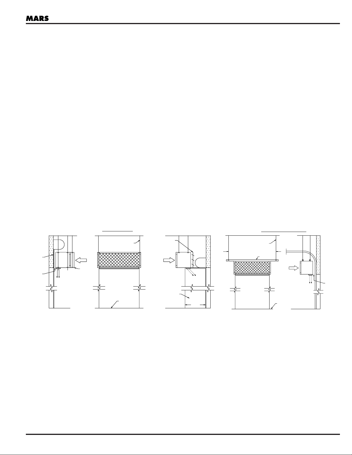
GENERAL INSTALLATION INSTRUCTIONS
All Mars Air Doors are structural trusses which span their total width without intermediate support. Air curtains are
generally installed on the inside, warm side, or clean side, of the areas to be separated. For special applications contact
the factory.
IMPORTANT NOTE: Air curtains equipped with optional steam/hot water coils require additional suspension in
order to provide access to unit motor(s) without breaking into the steam/hot water piping (Fig. 1). It is
recommended that coils be suspended independently of the air curtains with an additional threaded rod at
either end of the coil. It is recommended that the threaded rods be sized and installed such that the rods pass
through the upper flange and thru the lower flange and extend below the bottom of the air curtain approximately
two (2") inches. (NOTE: be sure and secure with nuts on top and on bottom.) This allows units to be lowered to a
point where suspension is from the top flange only. If the coil is independently suspended, full access to the front
(inlet) side of the air curtain is available. Drill screws securing coil to air curtain must be removed prior to lowering
air curtain.
SUSPENSION: All Models
Basic installation is accomplished using four (4) threaded rods (furnished by the installer) suspended from the ceiling.
Mounting holes are 5/8" diameter. See IMPORTANT NOTE above.
DOOR
LOWERED
MINIMUM
CLEARANCE
ROLL-UP DOOR
RECOMMENDED
STANDARD
HANGER RODS
FOUR (4) REQD.
OPTIONAL
STM/HW
COIL
DISCHARGE
(Fig. 1) (Fig. 2)
DOOR OPENING
LINE OF
FIN. FLOOR
BAFFLE BETWEEN
ROLL AND AIR
CURTAIN HOUSING
AIR FLOWAIR FLOW
SIDE BAFFLES
TO FLOOR
TWO (2) 3/4" PLYWOOD
SHEETS ANCHORED
TO FLOOR AND WALL
INSIDE
DISCHARGE
~
18"±
OUTSIDE
OF
BLDG.
ROD CENTERS OUTSIDE OF DOOR FRAME
DOOR OPENING
OVERSIZED ROLL-UP DOOR
STANDARD
HANGER RODS
FOUR (4) REQ'D.
3" CHANNEL
(Fig. 3)
LINE OF
FIN. FLOOR
AIR FLOW
DISCHARGE
MINIMUM
CLEARANCE
Page 4
CEILING SUSPENSION is recommended to prevent the possibility of the unit falling if a wall to which the unit is mounted,
is hit by a truck or material handling device. If however, wall or bracket mounting is preferred, additional holes may be
drilled in the side panels of the housing.
NOTE: Bracket/Support mounting is not generally recommended for Air Curtains equipped with steam or hot
water coils. Suspension by threaded rods with independent suspension of coils is recommended.
NOTE:
Mounting height determined by the minimum clearance between the housing of the Air Curtain and the travel of the
horizontal door leaves at the 90° track bend, when raised and lowered.
DISCHARGE ADJUSTMENT – GENERAL
All air curtains are provided with adjustable horizontal airfoil blades (vanes) in the discharge grille. Blades are manually
adjustable and are for directing the air stream inward or outward through and arc of 90 degrees. The typical setting is 15
degrees toward the outside.
NOTE: The final angle of adjustment is determined by the intensity of the wind and/or the pressure differential
between the areas being separated. See page 12.
VOLUME ADJUSTMENT
Models WMI and WMH are equipped with the exclusive Mars Air Doors gear drive volume control when supplied either
unheated or with a steam/hot water coil. For wind stopping and negative pressure applications, full air volume is
recommended. See page 12 for additional notes on volume control adjustment.
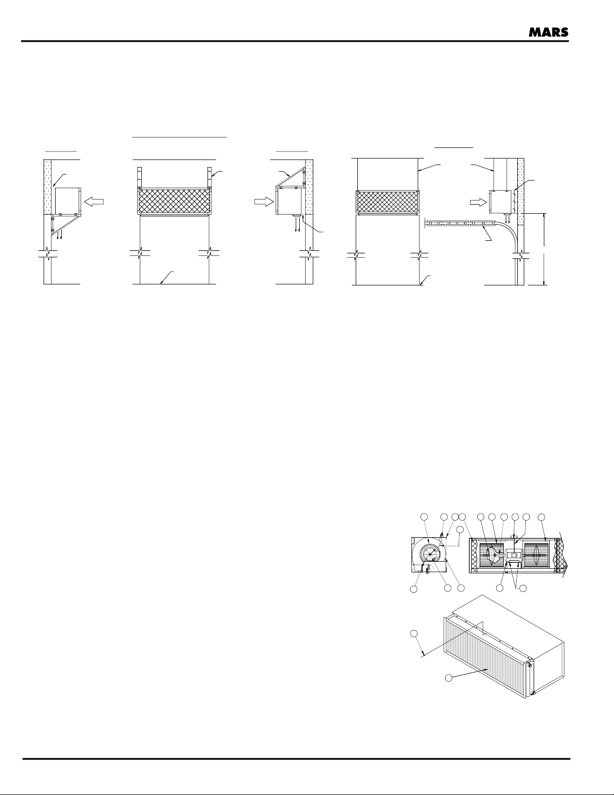
DISASSEMBLY INSTRUCTIONS
1. a. Non-heated Models: Turn-off electrical power, then detach inlet screen (1)
b. Heated Models: Turn-off electrical power, then reference heating coil
diagram (page 9) and steps 8 thru 13 on this sheet.
2. Disconnect flexible electrical cable (3) from conduit box (4); pull through.
3. Detach scroll cover (5)
4. Detach 4 bolts (9) holding motor (10).
5. Remove motor (10).
6. Detach wheels (7) by loosening set screws (6) holding each blower wheels
(7) to shaft (8). With a screwing motion detach the wheels.
7. To assemble and secure items (1) thru (10). Reverse Steps 1 thru 6 above.
8. Close manual stop valves on the supply and return lines (drain system
when applicable).
9. Detach heating coil (11) from supply and return line fittings.
10. Loosen the heating coil screws (12), located horizontally across the top and
bottom of housing.
11. Prior to detaching the screws (12), manually or mechanically secure
temporarily the heating coil unit for removal.
12. When all screws (12) are detached, remove the entire heating coil unit by means of manually or mechanically lifting
and pulling forward (toward installer).
13. To assemble and secure items (11) and (12), reverse steps 8 thru 12 above.
Mars Industrial Air Curtain
4 Tel: (800) 421-1266 • Internet: www.marsair.com
AIR FLOWAIR FLOW
AIR FLOW
LINE OF
FIN. FLOOR
LINE OF
FIN. FLOOR
STEEL ANGLE OR CHANNEL
WALL BRACKET (BOLT
TO WALL) BY INSTALLER
DOOR OPENING
DOOR OPENING
DISCHARGE
OUTSIDE
OF
BLDG.
INSIDE
STANDARD
HANGER RODS
FOUR (4) REQ'D.
DISCHARGE
DISCHARGE
INSIDE
BLDG.
OF
OUTSIDE
RECOMMEND
BAFFLE BETWEEN
WALL AND AIR
CURTAIN HOUSING
MINIMUM
CLEARANCE
SUPPORTED SUSPENDED
SUPPORTED / SUSPENDED BRACKETS
LOW RISE DOOR
MINIMUM
CLEARANCE
SEE NOTE #1
discharge and wall.
clearance between
to allow 8" minimum
Alter springs on door
INSIDE
OUTSIDE
BLDG.
OF
4 8
76
5
4
3
10
9
7
1 2
5
10
9
3
12
11
Page 5

MAINTENANCE INSTRUCTIONS
GENERAL
High voltage and rotating parts can cause serious or fatal injury. Safe
installation, operation and maintenance must be performed by qualified personnel. Familiarization with, and adherence to,
NEMA MG2, the National Electrical Code (NFPA70), and local codes is recommended. It is important to protect personnel
from possible injury.
VISUAL INSPECTION
Maintenance includes routine visual inspection of Air Curtains to insure efficient performance with no loss in heat or
separating capability.
BLOWER WHEELS
Once a year, clean blower wheels with compressed air jet or vacuum equipment, then manually wipe down.
AIR FILTERS (if applicable)
Once a year or earlier, depending upon the need and quality of clean air environment required, change all disposable
(throw-away) filters, type extended surface pleated media. For permanent (washable) aluminum filters wash, clean, air dry
and viscous coat, at least once a year.
MOTORS
Standard direct drive motors have sealed bearings and require no lubrication.
AIR CURTAIN OPERATING SEQUENCES
All Models: Be sure electrical power is turned “ON”.
NO CONTROLS
(Power Circuit Only)
Unit fan(s) will start and stop as the power circuit “makes” or “breaks”.
OPTIONAL MOTOR CONTROL PANEL
(Remote or Unit-mounted)
Factory prewired motor control panel includes the selected NEMA type enclosure, required number of magnetic
contactors, thermal overload relays, auxiliary contact (normally open), step down control circuit transformer (standard-120
volts), fuse / fuse holder, line and control circuit terminal blocks. A step down control circuit transformer and over-current
protection are often used to provide a control circuit voltage (secondary) lower than line voltage (primary) for reasons of
operator safety.
Each magnetic contactor contains a mechanism that “makes” and “breaks” a set of contacts in the motor circuit. In the
contactor’s control circuit, when the coil is energized, moveable contacts close against the stationary contacts, thus
completing the electrical circuit. De-energizing the coil breaks the circuit. A thermal protective circuit in each thermal
overload relay guards the motor against excessive temperature conditions by means of the built-in metallic elements.
Magnetic contactors are frequently controlled by the standard control options indicated below or other options such as:
on delay/off delay relays, timers, pressure switches, float switches, thermostats, etc.
OPTIONAL CONTROLS
(Field Installed)
Door Limit Switch – Normally Open: Switch opens and closes as door moves up and down, making and breaking the
control circuit.
Push-Button Control Station: Start and Stop buttons make and break the control circuit.
Hand-Off-Auto Switch with Door Limit Switch: When the switch is in the OFF position the air curtain is inoperable. In the
HAND position, the air curtain will run continuously and overrides the door limit switch. In the AUTO position, the door
limit switch causes the air curtain to operate as the door opens and closes.
Tel: (800) 421-1266 • Internet: www.marsair.com 5
Mars Industrial Air Curtain
Page 6

OPTIONAL ELECTRIC HEAT COIL
(Factory Installed, Interlocked with Air Curtain)
Electric heating coils interlocked with air curtain control (secondary) circuit in unit or remote motor control panel, are
frequently control by the standard control options detailed above, as well as those on page 9.
No Thermostat: Air curtain and heating coil operate simultaneously through interlocking, whenever the air curtain control
circuit is energized.
Thermostat (Field Installed): Air curtains having single (one-stage) heating elements, are controlled by a single stage
thermostat. When the air curtain control circuit closes, the air curtain fan will run and through interlocking, will enable the
heater circuit. On a call for heat, the thermostat will energize the heater control contactor. The thermostat will then cycle
the heater as needed, as long as the air curtain control circuit is closed (fan is running). When the air curtain control circuit
opens, the heater circuit is disabled, the heater will deenergize and the fan will shut off. Air curtains having multiple stages
of heat operate in a similar fashion, except that individual stages of heat are cycled on and off by the individual stages of a
multi-stage (2 or 3) thermostat.
OPTIONAL STEAM/HOT WATER, DIRECT-FIRED AND INDIRECT FIRED GAS HEATING.
In addition to unit-mounted electric heat and steam/hot water coils, direct and indirect fired gas heating units can be
supplied for air curtains.
GAS HEATING OPTIONS
FUELS
Mars Air Doors gas-fired options are designed to operate on natural gas having a specific gravity of approximately 0.60
and a thermal value ranging from 950 to 1125 BTU per cubic foot. When burned completely, carbon dioxide in the flue
gases will approach 10% with negligible carbon monoxide. These options can be set up for LP gas, having a specific
gravity of approximately 1.52 and a thermal value of 2500 BTU per cubic foot. When burned completely, carbon dioxide
will approach 12.5% with negligible carbon monoxide. Burner input ratings used in our literature are based on a thermal
value of 1000 BTU per cubic foot.
WIRING
All burners are pre-wired as far as practical. Refer to burner and submittal wiring diagrams before making any
connections. The burners must be electrically grounded in accordance with local codes or, in the absence of local codes,
with the National Electric Code (NFPA-70). Generally all burners, whether direct or indirect-fired, require a power source
connection that is separate from that of the air curtain unit. This Power source is commonly 115 volts. Most industrial air
curtains are supplied with three phase motors and either unit-mounted or remote control panels. These control panels are
not equipped with sufficient transformer capacity to power direct-fired or indirect-fired duct furnaces.
GAS PIPING
Gas piping and gas equipment installation and start-up should only be undertaken by experienced personnel that are
licensed to perform this type of work. It is the responsibility of the installing contractor to insure that all gas piping is sized,
installed and leak tested in accordance with local building codes or, in the absence of local codes, with the latest edition
of the National Fuel Gas Code, ANSI Z223.1 (N.F.P.A. NO. 54)
Mars Industrial Air Curtain
6 Tel: (800) 421-1266 • Internet: www.marsair.com
Page 7

INDIRECT-FIRED GAS HEATING
The indirect-fired gas heating option combines an industrial air curtain unit with one or more indirect-fired gas duct
furnaces. Individual furnaces may have inputs from 100 to 400 MBH, are available for operation on Natural or LP gas and
are both AGA and CGA certified. Duct furnaces are normally drop-shipped to the job and must be suspended
independent of the air curtain unit and field-connected to the intermediate section. The intermediate section merely
provides duct flange connections that mate with the appropriate duct furnace(s) and provide access doors for
motor/blower service. The intermediate section is assembled to the air curtain unit and shipped as a single assembly. In
addition to the four suspension/hanging points on the air curtain, there are two additional points on the intermediate
section. Each duct furnace requires four point suspension/hanging.
Each duct furnace is shipped with an “Installation Operation and Maintenance” manual. This manual should be carefully
reviewed before installing furnaces. Natural or atmospherically vented duct furnace must be supplied with a 115 or 230
volt power. Power vented duct furnace must be supplied with 115 volts with sufficient capacity for the ignition transformer
and the venter motor. Each furnace requires gas supply at a pressure not to exceed 1/2 PSIG (3.5kPa). If available supply
pressure exceeds 1/2 PSIG, it is the responsibility of the installer to provide appropriate high pressure regulation.
Vent systems for atmospherically (naturally) vented duct furnaces may employ “manifolding” or combining vents into one
stack for roof penetration if allowed by state/local codes. Please refer to the National Fuel Gas Code ANSI Z223.1 (N.F.P.A.
No. 54) for additional information on combining vents. If power vented duct furnaces are selected, each furnace must
have its own vent from furnace to termination device, however the vent pipe size is smaller and the vents may be
terminated horizontally (through a side wall) rather than requiring a roof penetration.
Indirect-fired air curtain systems are typically controlled by a door limit switch, which may be wired in parallel with a space
thermostat, allowing the system to operate as both a space heater and an air curtain. Contacts are provided in the air
curtain motor control panel for connection to the R and W thermostat connections on each duct furnace, thus taking the
place of the conventional thermostat.
CAUTION: Natural vented duct furnaces are equipped with blocked vent (spill) shutoff switches. Before attempting
start up, push the reset button in the upper right side of the draft diverter. The switch will shut down the unit if the
venting system becomes blocked or there is continuous spillage of flue products. The switch is temperature
activated and will not reset when it is hot.
DIRECT–FIRED GAS HEATING
The direct-fired gas heating option is available in two configurations. The first utilizes a “power burner” of the type used on
boilers. The burner fires down a stainless steel tube having a predetermined pattern of holes punched in it. The inlet air for
the air curtain is drawn over and through the tube, transferring heat to the air stream. This configuration is compact but is
only offered with On-Off controls and is limited to a temperature rise of approximately 30°F.
Direct-fired design options are shipped with detailed instruction manuals covering the specifics of the burner that is
supplied.
Tel: (800) 421-1266 • Internet: www.marsair.com 7
Mars Industrial Air Curtain
Page 8

AIR CURTAIN OPTIONAL EQUIPMENT
MOTOR CONTROL PANELS
Remote mounted (Standard) and Unit Mounted (optional), includes required number of magnetic contactors, thermal
overload relays, auxiliary contact (N.O.), step down transformer for low voltage control, fuse/fuse holder, line and control
circuit terminal blocks. Purchaser must furnish safety shut-off device (e.g.: fused disconnect switch) in accordance with
applicable electrical code.
DOOR LIMIT SWITCH (MICRO)
Used to provide automatic control of air curtain when interlocked with controls in motor control panel.
MOUNTING
1. Mount on flat rigid surface.
2. Use lock washers with mounting screws.
3. Connect conduit to complete seal.
ADJUSTMENT
Combination Roller-Plunger Door Limit Switch has a Horizontal adjustment of 90 degrees.
PUSH-BUTTON CONTROL STATION
Used for manual control of air curtain. Furnished in NEMA-1 enclosure for surface mounting. Actual dimensions 3-5/8"
high X 2" wide X 2" deep. Maximum service 600 volts, access through either top or bottom of enclosure.
Mars Industrial Air Curtain
8 Tel: (800) 421-1266 • Internet: www.marsair.com
MARS AIR DOORS
R
MARS AIR DOORS
START
STOP
U
SA
L
Page 9

HAND-OFF-AUTO SWITCH/DOOR LIMIT SWITCH
Standard in Remote Control Panels
Optional Remote Station
Provides either continuous (HAND position) or automatic (AUTO position) control through a door limit switch.
ELECTRIC HEATING COIL – INTERLOCKED WITH AIR CURTAIN
Single or multi-stage coils are available to provide clean and efficient heat. Responds quickly, ideal for hard to heat areas.
Safe and nearly maintenance free, heating coils are easily installed, requiring only electrical connections.
V-BANK AIR FILTER HOUSING
Available with either throwaway or permanent (washable) air filters. Filters are changed by simply sliding the dirty filters out
from either side of the housing and then inserting clean filters in their place.
FLAT BANK AIR FILTER HOUSING
Available with two inch extended surface pleated high loft media. Filter changing is accomplished by simply removing
bottom center section of filter housing and sliding filters to the center from both sides and removing, insert new filters and
slide them to each end and replace center filter housing section.
Tel: (800) 421-1266 • Internet: www.marsair.com 9
Mars Industrial Air Curtain
Intake Screen must be
Installed at all times.
AIR CURTAIN
AIR FLOW
Heater ON/OFF
Switch
R
OFF
HAND AUTO
U
L
SA
MARS AIR DOORS
Filter Bank
Page 10

VERTICAL MOUNT AIR CURTAIN HOUSING
Available as an alternative to the more common standard horizontal mounting. Features typically include floor mount
flange and bottom intake plenum. This method of installation can be used where head space above door openings is
insufficient or as an air shower to contain vapors for spray finishing or clean room applications. See page 14 and 15.
ENERGY ABSORBING PLENUM
Available option for use with vertical mounting. The purpose of the plenum is to dissipate the force of the high velocity
discharge air flow from the air curtain mounted at the opposite side of the opening.
INDIRECT-FIRED GAS AIR CURTAINS
NOTE: Naturally vented duct furnace vents may be manifolded per manufacturer’s instructions or per ANSI Z223.
Power vented duct furnaces must be individually vented from furnace to termination device.
Mars Industrial Air Curtain
10 Tel: (800) 421-1266 • Internet: www.marsair.com
DIRECT-FIRED GAS AIR CURTAINS
NOTE: The gas inlet sizes below for UL rated, On-Off, natural gas burners.
AIR NO. OF INPUT VENT GAS APPROX.
CURTAIN DUCT BTUH SIZE INLET SIZE NET WEIGHT
MODEL NO. FURNACES RATING GRAVITY POWER NATURAL LP EA. FURNACE
1/2"
1/2" 229
3/4"
1/2" or 3/4" 251
3/4"
1/2" or 3/4" 260
3/4"
1/2" or 3/4" 309
3/4"
1/2" or 3/4" 251
3/4"
1/2" or 3/4" 260
3/4"
1/2" or 3/4" 309
3/4"
1/2" or 3/4" 386
3/4"
1/2" or 3/4" 400
3/4"
1/2" or 3/4" 309
3/4"
1/2" or 3/4" 309
3/4"
1/2" or 3/4" 386
3/4"
1/2" or 3/4" 400
3/4"
1/2" or 3/4" 309
3/4"
1/2" or 3/4" 309
WMI-96
WMI-108
WMI-120
WMI-144
WMI-168
WMI-192
WMH-48
WMH-60
WMH-72
WMH-96
WMH-108
WMH-120
WMH-144
WMH-168
WMH-192
2
2
2
2
3
4
1
1
1
2
2
2
2
3
4
200,000
225,000
250,000
300,000
225,000
250,000
300,000
350,000
400,000
300,000
300,000
350,000
400,000
300,000
300,000
8"
8"
8"
10"
8"
8"
10"
10"
12"
10"
10"
10"
12"
10"
10"
5"
5"
5"
6"
5"
5"
6"
6"
6"
6"
6"
6"
6"
6"
6"
NO. OF BURNER BURNER GAS
MODEL LENGTH INPUT BURNERS MODEL NO. HP INLET SIZE
96 251,000 1 RE4400DS 1/6 3/4
108 261,000 1 RE4400DS 1/6 3/4
120 292,000 1 RE4400DS 1/6 3/4
WMI 144 350,000 1 RE4400DS 1/6 3/4
168 392,000 1 RE4400DS 1/6 3/4
192 462,000 2 RE4400DS 1/6 3/4
96 343,000 1 RE4400DS 1/6 3/4
108 347,000 1 RE4400DS 1/6 3/4
120 408,000 1 RE4600B 1/4 3/4
WMH 144 443,000 1 RE4600B 1/4 3/4
168 517,000 1 RE4600B 1/4 3/4
192 650,000 2 RE4600B 1/4 3/4
Page 11

Tel: (800) 421-1266 • Internet: www.marsair.com 11
Mars Industrial Air Curtain
SET UP AND ADJUSTMENTS
Air curtain units require some amount of set-up and adjustment for optimum performance. Units being used to minimize
the effects of natural wind may require re-adjustment as outdoor conditionals change. The chart below provides
suggested guidelines for directional discharge louver adjustment.
AIR CURTAIN ANGLE
APPLICATION LOCATION DISCHARGE SET-UP
Windstopping Inside Outside 15-20°
Initialy the "split" should be just at the
Perimeter Door
outside of the door opening (threshold).
Velocity is correct if height of the air
stream toward the outside, once it has
split, is 18-24". Adjusting vanes toward
the outside will reduce this height,
adjusting them to the inside will
increase it.
Insect Control Inside if Windstopping Outside 15-20°
Same as above, except split should be
Perimeter Door is also desired.
3-6" outside of doorway (in front of
Outside for best
threshold).
insect control.
Enviromental Heated Side Perpendicular to
Adjust angle more toward unheated side
Separation floor or slight
and/or adjust volume damper(s) if needed
Interior: toward unheated
to reduce any stirring up of dust/debris.
Heated/Unheated side.
Enviromental Non-Air Conditioned Toward non-air
Adjust angle more toward non-air
Separation Side conditioned side.
conditioned side and/or adjust volume
Interior:
damper(s) if needed to reduce any stirring
Air Conditioned/
up of dust/debris.
Non-Air Conditioned
Enviromental "Clean Side" Perpendicular to
Adjust angle more toward clean side
Separation floor or slight
and/or adjust volume damper(s) if needed
Interior: toward clean
to reduce any stirring up of dust/debris.
Dust-Dirt/Clean side.
Ovens Outside of oven Slight angle
toward oven.
Cold Storage/ Outside (warm) side 20° toward out-
If air flow at floor level is "into" cooler,
Freezers side (warm).
decrease volume. If air flow is out, increase
volume. Adjust until no flow is detected.
Page 12

Mars Industrial Air Curtain
12 Tel: (800) 421-1266 • Internet: www.marsair.com
WIRING SPECIFICATIONS
GENERAL
All models are supplied with direct-drive, double shafted motors with sealed bearings. These motors are built totallyenclosed-non-ventilated (TENV) but are applied and rated as totally-enclosed-air-over (TEAO). For this reason along with
typical service factors of 1.15, you may encounter situations where the amps in the table below exceed the individual or
aggregated nameplate amperages.
Single phase motors are internally protected while three phase models require external overload protection (Control
Panel/Starter).
OF
MOTORS
WMI-48
1
2 2.13
N/A 12.6
11.4 5.7 4.6
WMI-60
1
3 2.65
N/A 15.7
14.2 7.1 5.7
WMI-72
1
3 3.17
N/A 18.7
17 8.5 6.8
WMI-96
2
2 4.26
N/A 25.2
22.8 11.4 9.1
WMI-108
2
3 5.38
N/A 31.8
28.8 14.4 11.5
WMI-120
2
3 5.60
N/A 33.1
29.9 15 12
WMI-144
2
3 6.34
N/A 37.5
33.9 17 13.6
WMI-168
3
3 8.07
N/A 47.7
43.2 21.6 17.3
WMI-192
4
2 8.52
N/A 50.4
45.6 22.8 18.2
WMH-48
1
5 4.69
N/A 18.4
16.6 8.3 6.6
WMH-60
1
5 6.21
N/A 24.3
22.0 11.0 8.8
WMH-72
1
7 6.65
N/A 26.0
22.3 11.1 8.9
WMH-96
2
5 9.39
N/A 36.8
33.2 16.6 13.3
WMH-108
2
5 11.80
N/A 46.2
41.8 20.9 16.7
WMH-120
2
5 12.42
N/A 48.6
44.0 22.0 17.6
WMH-144
2
7 13.30
N/A 52.1
44.6 22.3 17.8
WMH-168
3
5 17.70
N/A 69.3
62.7 31.3 25.1
WMH-192
4
5 18.76
N/A 73.4
66.4 33.2 26.6
MODEL
NUMBER
SINGLE PHASE UNITS THREE PHASE UNITS
AMPS PER UNIT AMPS PER UNIT
HP/MOTOR KW 115/1 230/1 208/3 230/3 460/3 575/3
N/A
N/A
N/A
N/A
N/A
N/A
N/A
N/A
N/A
N/A
N/A
N/A
N/A
N/A
N/A
N/A
N/A
N/A
Page 13

Tel: (800) 421-1266 • Internet: www.marsair.com 13
Mars Industrial Air Curtain
SUGGESTED PIPING LAYOUTS
The piping layouts below depict suggested steam and hot water piping for commercial air curtains. All coils are furnished
with 1/2" MPT connections. “Same End Connection” is the only configuration available for commercial models.
STEAM HEATING COIL - SAME END CONNECTION
A
H
E
F
D
B
C
A
G
STEAM HEATING COIL - OPPOSITE END CONNECTION
A
F
H
D
E
B
C
A
G
HOT WATER HEATING COIL - SAME END CONNECTION
HOT WATER
RETURN
H
A
HOT WATER
HOT WATER
J
RETURN
SUPPLY
I
HOT WATER HEATING COIL - OPPOSITE END CONNECTION
H
A
HOT WATER
SUPPLY
J
I
Page 14

Mars Industrial Air Curtain
14 Tel: (800) 421-1266 • Internet: www.marsair.com
A. Globe or Gate Valve
B. 15" Swing Check Valve
C. Trap
D. Strainer with Blow Down Valve
E. Dirt Pocket
F. Steam Main
G. Return Main
H. Quick Air Vent Valve
I. Drain Valve
J. Hand Flow Control Valve
NOTES:
1. Provide swing joints or expansion compensators in all piping to prevent damage to coil caused by expansion and
contraction of piping.
2. Support piping independently of heating coil.
3. Quick vent air valve (H) must be used with all low pressure closed return systems unless an air eliminator in the boiler
room, is employed. This valve should be omitted with open return or vacuum return systems.
4. Trap (C) – must be used with all dry return systems. (Omitted with individual wet returns). The trap must be one that
will pass both condensate and air at system temperate.
5. Return main (G) – when high pressure is available, the return main may be located at a higher level than the return
outlet of the heating coil. A check valve between the trap and the return main, just before the riser, must be installed to
prevent back flow of the condensate.
6. When attaching external piping to header pipes of the heating coil, apply force with a second pipe wrench so as not to
damage tube connections to headers.
VERTICAL AIR CURTAIN INSTALLATION PROCEDURE
UNIT LOCATION
Position the air curtain 6" from the door opening and tight against the inside wall, with the discharge nozzle facing the
desired direction of air flow. If the air curtain is to be mounted outside, please consult the factory for further direction.
Flanges are fitted at the bottom of the unit for attachment.
NOTE: If there is an overhead door allow the necessary clearance for the door rails, the door itself, and any
hardware mounted to the door. The air curtain can be mounted up to 2" off the wall. If 2" is not sufficient, consult
the factory for further direction.
LEVELING
The air curtain should be leveled horizontally and vertically. Appropriate shims can be used at the floor or wall for
adjustment.
ANCHORING TO A CONCRETE FLOOR
Drill holes in the floor slab at the proper locations for installing concrete anchors. Anchors should be sized to your
particular application. We suggest a minimum of 5/8" diameter, 2-5/8" deep concrete anchors. Install concrete anchors
according to the manufacturer’s instructions.
ANCHORING TO A WOOD FLOOR
Use lag screws or lag bolts to secure the unit to the floor. Screws/bolts should be sized to your particular application. We
suggest that a minimum of 3/4" diameter, 3" long screws/bolts be used. There are mounting holes located at the top of
the air curtain’s housing. These holes are provided for securing the top of the unit to the wall. The holes are 5/8" diameter
and accept a 1/2" threaded rod. The threaded rod is attached to the unit, and extends through the wall to a concrete base
plate (by installer) mounted on the exterior of the wall. An alternative to exterior mounting is to mount a plate on the inside
wall.
UNIT PROTECTION
The likelihood of damage increases greatly when units are installed vertically. To protect units from damage from forklifts,
pallet jacks, racks, etc., it is recommended that units be protected from traffic by installing steel posts and fencing if
appropriate.
Page 15

Tel: (800) 421-1266 • Internet: www.marsair.com 15
Mars Industrial Air Curtain
SERVICE CLEARANCE
Provide a minimum of one (1) foot of clear space on three sides of the air curtain, for operation and service access (the
fourth side being mounted to the wall).
AIR CURTAIN WARRANTY COVERAGE, PERIOD, EXTENT AND LIMITATIONS (Equipment only)
Mars Air Doors warrants that Mars Air Doors equipment 1) is free from defects in materials and workmanship and
2) conforms to Mars Air Doors published specifications. The warranty period for Mars Air Doors equipment is an (18)
eighteen month period commencing on its date of shipment. The date on the customer’s invoice is the date of shipment,
unless Mars Air Doors or you reseller informs you otherwise.
Mars Air Doors will provide free replacement of any part that fails as a result of a defect in material or manufacturer’s
workmanship. Changes in operational specification parameters that are different from those provided on the original
purchase order are not covered.
Mars Air Doors equipment is inspected and tested before packaging and is shipped in working condition. The Warranty
for Mars Air Doors equipment only covers free-of-charge replacement of failed parts. The warranty does not cover labor or
transportation expenses that may be required to provide and to install replacement parts. Because in many instances, it is
impossible to determine cause of failure, customer may be responsible for transportation charges associated with
replacement of failed part.
Mars Air Doors does not warrant uninterrupted or error-free operation of Mars Air Doors equipment. Under no
circumstances is MARS liable for any of the following: 1) Third-party claims against you for damages; or 2) Special,
incidental, or indirect damages or for any economic consequential damages (including lost profits and savings), even if
MARS , its suppliers or its resellers is informed of their possibility.
This warranty does not cover repair or exchange of Mars Air Doors equipment resulting from misuse, accident,
modification, unsuitable physical or operating environment, improper maintenance and installation by customer, or failure
caused by a product for which Mars Air Doors is not responsible. This warranty does not cover damages caused by
mishandling during transportation.
This warranty is voided by removal or alteration of Mars Air Doors equipment or parts identification labels, by improper
installation of equipment and resulting non-compliance to federal, state and local codes and regulations. Additionally,
Mars Air Doors reserves the right to void the warranty for non-payment of invoice.
AIR FLOW
AIR FLOW
AIR FLOW
AIR FLOW
6"
2"
Page 16

16 Tel: (800) 421-1266 • Internet: www.marsair.com
 Loading...