


The
560
REFERENCE SERIES
CHANGEGIVER
PRODUCT MAINTENANCE
HANDBOOK
CashFlow®CashFlow®CashFlow®CashFlow®CashFlow®Ca
shFlow
Flow
ow
®
ashFlow
hFlow
low
w
CashFlow®CashFlow®CashFlow®CashFlow®CashFlow®Ca
shFlow
Flow
ow
®
ashFlow
hFlow
low
w
CashFlow®CashFlow®CashFlow®CashFlow®CashFlow®Ca
shFlow
Flow
ow
®
ashFlow
hFlow
low
w
CashFlow®CashFlow®CashFlow®CashFlow®CashFlow®Ca
shFlow
Flow
ow
®
CashFlow®CashFlow®CashFlow®CashFlow®Cash
®
CashFlow®CashFlow®CashFlow®CashFlow®CashFl
®
CashFlow®CashFlow®CashFlow®CashFlow®CashFlow
CashFlow®CashFlow®CashFlow®CashFlow®CashFlow®C
®
CashFlow®CashFlow®CashFlow®CashFlow®CashFlow®C
®
CashFlow®CashFlow®CashFlow®CashFlow®CashFlow®C
®
®
CashFlow®CashFlow®CashFlow®CashFlow®Cas
®
CashFlow®CashFlow®CashFlow®CashFlow®CashF
®
CashFlow®CashFlow®CashFlow®CashFlow®CashFlo
CashFlow®CashFlow®CashFlow®CashFlow®CashFlow
®
CashFlow®CashFlow®CashFlow®CashFlow®Cash
®
CashFlow®CashFlow®CashFlow®CashFlow®CashFl
®
CashFlow®CashFlow®CashFlow®CashFlow®CashFlow
®
®
®
25777 G9 142891044

CashFlow 560 changegiver Product Maintenance Handbook
Published by :
For information on translations in your country, please write to the Technical Communications
Manager at the above address.
MEI
Internet: http://www.meigroup.com
CashFlow560 changegiver Product Maintenance Handbook
©, MEI UK International Ltd., 1997.
All rights reserved.
Except as permitted under the relevant local legislation, no part of this publication may be
copied, transmitted, transcribed, or distributed in any form or by any means, or stored in a
database or retrieval system, or translated into any language (natural or computer), without the
prior written permission of MEI.
MEI, CashFlow and the MEI device are registered trademarks.
©, MEI., 1997.
MEI reserves the right to change the product or the product specifications at any time. While
every effort has been made to ensure that the information in this publication is accurate,
MEI disclaims any liability for any direct or indirect losses (howsoever caused) arising out of
use or reliance on this information.
This document does not necessarily imply product availability.
Part Number : 142891044
This Edition (December 1997) Printed in the United Kingdom.
ii ©, MEI., 1997.

CashFlow 560 changegiver Product Maintenance Handbook
SAFETY.......................................................................................1
OVERVIEW.................................................................................2
INSTALLATION..........................................................................5
FIXING THE CHANGER IN POSITION................................6
REJECT LEVER CLEARANCE ...........................................9
CHUTE ALIGNMENT ...........................................................9
CONNECTION & OPERATING VOLTAGE ........................10
FILLING CHANGE TUBES ................................................10
INSTALLATION CHECK LIST............................................11
CONFIGURATION...................................................................12
VIA KEYPAD ......................................................................12
VIA MEI
TABLE OF CONTENTS
COIN QUALITY..........................................................10
COIN FEED RATE.....................................................10
USING THE KEYPAD................................................13
Dispensing Coins..............................................13
Setting Prices ...................................................14
Automatic Tube Float........................................15
Automatic Tube Inventory.................................15
Resetting the Tube Counts...............................16
Cancelling Credit ..............................................16
ROUTE ALPHA 250 TERMINAL.......................17
KEY FUNCTIONS......................................................18
USING THE TERMINAL............................................19
VISUAL AUDIT..........................................................21
Visual Audit Interrogation..................................21
DIAGNOSING TERMINAL PROBLEMS ...................33
Testing the Terminal.........................................34
REPLACING MODULES........................................................35
©, MEI., 1997. iii

CashFlow 560 changegiver Product Maintenance Handbook
REMOVING THE COIN STORAGE CASSETTE................35
REFITTING THE COIN STORAGE CASSETTE................36
REMOVING COIN TUBES........................................37
Removing the Designators ...............................39
TUBE POSITIONS..............................................................40
COIN SIZES FOR EACH TUBE.........................................41
TUBE & DESIGNATOR COMBINATIONS.........................42
AUSTRALIAN COINSET ...........................................42
FRENCH COINSET...................................................43
GERMAN COINSET..................................................44
ITALIAN COINSET.....................................................45
SPANISH COINSET ..................................................47
UNITED KINGDOM COINSET..................................48
DESIGNATOR AND COIN THICKNESS ...................49
ADDING A NEW COIN.......................................................49
REMOVING THE ACCEPTOR...........................................50
REFITTING THE ACCEPTOR............................................50
REMOVING THE DISCRIMINATOR BACK COVER.51
REMOVING THE SEPARATOR .........................................53
REMOVING THE SEPARATOR SOLENOID BANK..54
Removing the Top Level Sensor Assembly......55
REMOVING THE ACCEPT GATE.............................56
REMOVING THE DISPENSER...........................................57
REMOVING THE DISPENSE ARMS.........................58
REMOVING THE KEYPAD AND TRANSFORMER...........59
REPLACING FUSES..........................................................60
REMOVING THE CONTROL BOARD ...............................61
4 PRICE/1 PRICE MODE SWITCH...........................61
CONNECTORS (EXECUTIVE, BDV and MDB)........62
CONNECTORS (4 PRICE)........................................63
CONNECTORS (MUL T-IINTERF ACE- MDB 4 PRICE/1
PRICE).......................................................................64
FAULT-FINDING ......................................................................65
TROUBLESHOOTING THE CASHFLOW® 560 UNIT.......69
iv ©, MEI., 1997.

CashFlow 560 changegiver Product Maintenance Handbook
CLEANING THE ACCEPTOR ..............................................76
CLEANING (General).........................................................77
COMPATIBILITY......................................................................80
BILL VALIDATOR INTERFACE .........................................82
MEI BINDER .............................................................................86
MEI OFFICES ...........................................................................88
MEI DISTRIBUTORS..............................................................89
INDEX.........................................................................................95
©, MEI., 1997. v

CashFlow 560 changegiver Product Maintenance Handbook
vi ©, MEI., 1997.

CashFlow 560 changegiver Product Maintenance Handbook
SAFETY
International & National Standards
Conformance
When installed and operated according to the
instructions for the particular unit, CashFlow
products are designed to meet the applicable
Safety and Electro Mechanical Conformance
standards for any country in which they are used.
CashFlow
construction. No safety earth connection is
necessary or provided.
Dangerous Environments
Do not operate in the presence of flammable
gases, fumes or water.
Disposal of Product
Do not dispose of any parts of this product by
incineration.
Rated Operating Voltage
The rated voltage is indicated on a clear see
through label above the changegiver keypad.
Always operate the changegiver from the type of
power source indicated on the label.
560 products are of class II
560
Warning: before removing or replacing modules
SWITCH OFF or ISOLATE the ELECTRICITY
SUPPLY to the host machine
THIS MANUAL IS PROVIDED FOR USE ONLY BY PERSONNEL
TRAINED TO UNDERTAKE ELECTRICAL INSTALLATION
©, MEI., 1997. 1

CashFlow 560 changegiver Product Maintenance Handbook
OVERVIEW
The CashFlow 560 changegiver incorporates many new features
as well as improving the high standards of security and reliability
which have become the hallmark of all MEI
products. The changegivers are completely modular
making it quick and easy to remove or replace any necessary parts.
The 560 changegiver is currently available in the following formats:
• Cashflow
A 4 price electro-mechanical changegiver. Interfaces
are provided for a credit display and credit relay if
required.
• CashFlow
This is a European Mode Executive changegiver
product with an electronic Protocol A serial interface.
• CashFlow
A BDV changegiver product with an electronic BDV
serial interface.
560 4 - Price
560 - Executive
560 - BDV
• CashFlow
A MDB changegiver product with an electronic MDB
serial interface.
2 ©, MEI., 1997.
560 - MDB
CashFlow 560 changegiver Product Maintenance Handbook
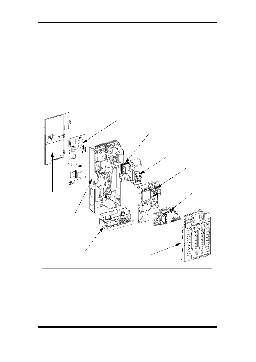
All of these changegivers are made up of the following modules:
Back Cover
Spine
• Control Board
• Spine
• Transformer (not used on BDV and MDB product)
• Keypad
• Dispenser
• Acceptor
• Separator
• Coin Storage Cassette
Control Board
Transformer
Keypad
Acceptor
Separator
Dispenser
There are several different types of machine interface loom
available as well as optional four and five digit display looms. All
changegivers have a keypad mounted on the front face. This
keypad is used for manually dispensing coins and reconfiguring
some of the settings which are accessible without requiring the use
of a MEI
terminal you can reconfigure the way the changer operates. This
Route Alpha 250 Terminal. If you have this support
Coin Storage Cassette
©, MEI., 1997. 3

CashFlow 560 changegiver Product Maintenance Handbook
includes changing from single to multivend, inhibiting coins, setting
the exact change equation etc.
The CashFlow
extension module (FEM) fitted, or this can be supplied for fitting at a
later date.
The FEM allows for reports to be supplied either via a hand-held
Audit 920 printer, or down-loaded via a terminal to a P.C..
MEI
These reports can include:
The process of obtaining data is detailed in the section of this book
concerned with the MEI
For further details of audit installation please refer to the MEI
900 Installation Guide, part number 143451999.
The products in this book can also be used in conjunction with a bill
validator. Further application details are given in the Bill Validator
Interface Installation (BVI) data sheet, part number 143949044.
Additional information on the BVI, audit FEM and the MEI
920 printer can be obtained from your MEI Distributor or MEI
regional office, the addresses of which are shown at the end of this
book.
®
560 product can be supplied with an audit fuction
• Value of cash manually filled
• Value of cash retained in the changegiver
• Value of cash sales
• Value of token sales
• Value of cash taken by the machine
• Value of cash to cashbox
• Value of cash dispensed as change
Route Alpha 250 terminal.
®
Audit
Audit
4 ©, MEI., 1997.
CashFlow 560 changegiver Product Maintenance Handbook
INSTALLATION
All changers have a keypad mounted on the front face. To install
and set the product up you should understand how the keypad
works and how to use it.
If in doubt the section on configuration shows you in more detail how
the keypad works.
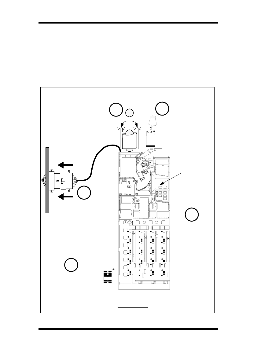
The 5 key points to note when installing any changegiver are:
Machine coin entry
should be aligned
centrally with the
coin entry cup
3
=
Correct
clearance of
2
reject lever
2-3mm
Voltage
Label
4
Fully
Connected!
1
Min. 2-6 coins
5
BCD
%
%
80
70
60
50
40
30
20
10
%
80
80
70
70
60
60
50
50
40
40
30
20
20
10
Follow correct
%
process to
80
firmly install
70
changegiver
60
50
40
20
10
Front View
A full installation check list is provided at the end of this section.
©, MEI., 1997. 5
CashFlow 560 changegiver Product Maintenance Handbook
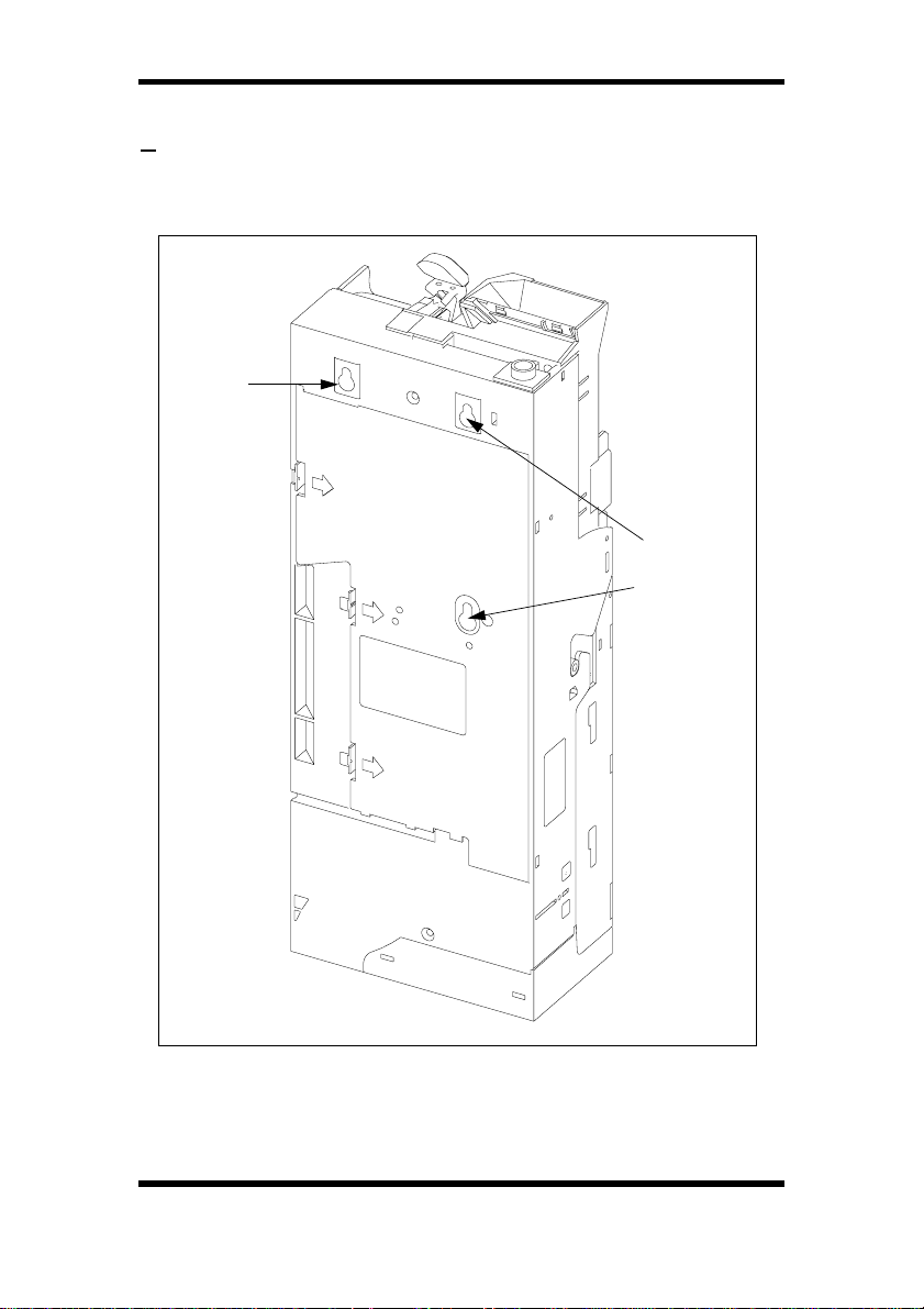
FIXING THE CHANGER IN POSITION
1 There are 3 keyhole fixing points on the rear of each changegiver.
It is recommended that only the top right hand fixing point is used
with a screw, the two fixing points on the left hand side should be
placed on studs.
Fix with a
screw
Place on
studs
Rear View
To ensure that the changegiver operates correctly it must be
mounted so that it hangs within +/-2° of vertical, from both front and
side elevations.
6 ©, MEI., 1997.
CashFlow 560 changegiver Product Maintenance Handbook
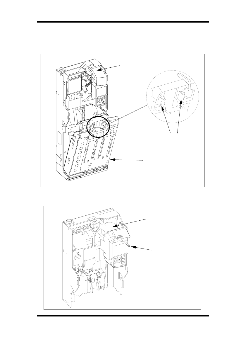
To gain access and fit the changer into the machine:
Remove the coin storage cassette by squeezing the blue tabs
together and unhook the cassette with a careful outwards and
upwards pull.
Cover Flap in
closed position
Press down at the back of the cover flap until it latches in the open
position. The top right hand fixing point is now accessible.
Blue Tabs
Coin Storage
Cassette
Cover Flap, in open
position, exposing
Fixing Screw
Keypad
Securing Screw
©, MEI., 1997. 7
CashFlow 560 changegiver Product Maintenance Handbook
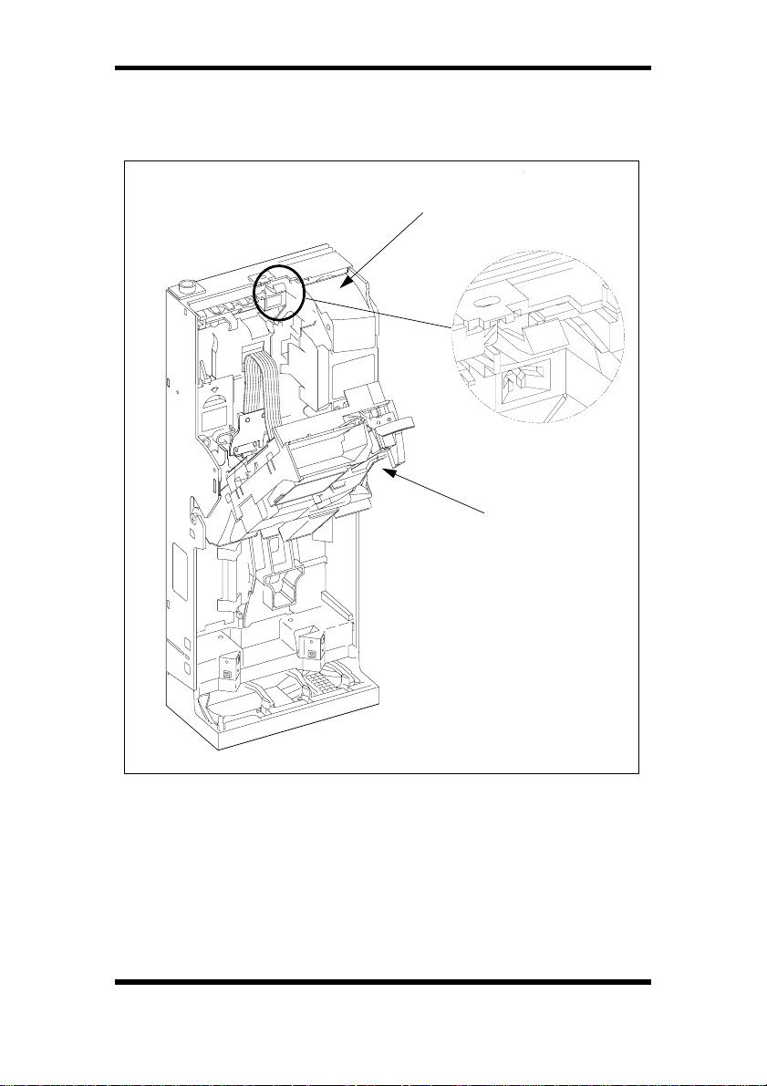
Unlatch the acceptor by pressing down on the blue acceptor release
catch. You may find it easier to use a small screwdriver. Lower the
acceptor forwards until it rests on the channel pins. The two left
hand keyholes are now accessible.
Cover Flap
Acceptor Release
Catch
Acceptor
Place the changegiver in the machine using all three keyholes. Fully
tighten the top right hand screw (under cover flap).
Refit the acceptor by carefully pushing back to its upright position.
You will hear the acceptor click into place.
Close the cover flap by pressing the lower left hand corner of the
flap.
8 ©, MEI., 1997.
CashFlow 560 changegiver Product Maintenance Handbook
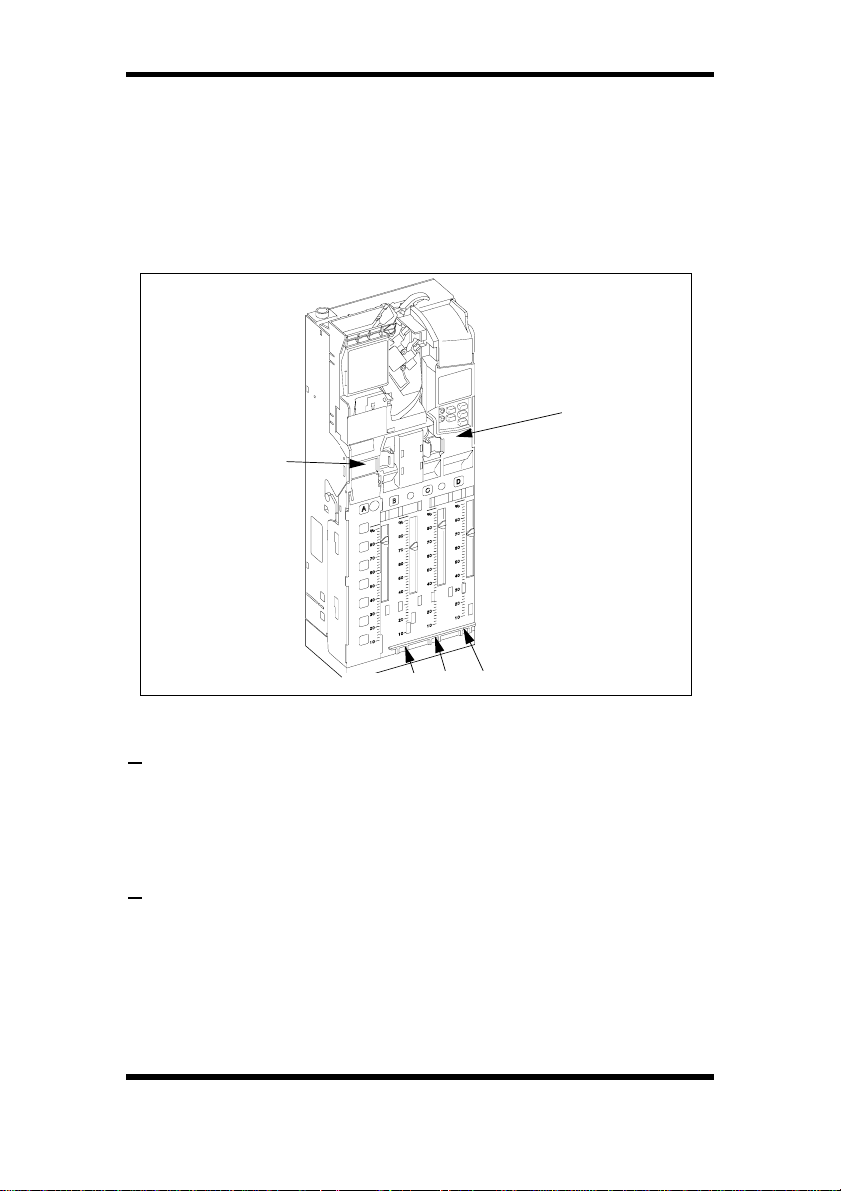
It is important that before fitting the cassette back into place you
make sure the dispense arms are in their parked positions i.e they
are as far forward as possible. Switch the machine on, and press the
yellow mode key on the keypad twice. This will park the arms
automatically for you. The dispense arms should protrude through
the bottom of the cassette after refitting.
Refit the coin storage cassette pressing each side to ensure the tab
ends engage in their slots on the spine.
Press Here
Press Here
Dispense Arms Should be Seen Here
REJECT LEVER CLEARANCE
2 There should be 2 to 3mm clearance between the reject lever on
the changegiver and the reject mechanism in the vending machine.
A smaller gap than this may cause poor acceptance, as the flight
deck lid may remain open.
CHUTE ALIGNMENT
3 The centre of the coin entry chute on the machine should be
aligned with the centre of the coin entry cup of the changegiver. The
alignment can be tested by taking the largest and smallest diameter
coins to be accepted and feeding a number through the product.
You should ensure that the coin exits, both return and cashbox, are
correctly aligned to the machine chuting. In particular, ensure there
are no gaps around the coin return chute and the base of the
changer which might allow coins to spill into the machine.
©, MEI., 1997. 9

CashFlow 560 changegiver Product Maintenance Handbook
CONNECTION & OPERATING VOLTAGE
4 One of the main causes of poor coin acceptance is insufficient
power. Always check the voltage. Poor electrical connections can
also lead to poor coin acceptance. To obtain the correct
performance from your changegiver, the connector should be fully
plugged in and the power to the machine switched on.
FILLING CHANGE TUBES
5 To ensure continued acceptance of high value coins there should
always be a minimum number of coins left in each tube, as defined
in the Tube and Designator Combinations section of this book. A
maximum fill level will ensure that additional coins above this level
will be routed directly to the coinbox.
Set the changer into automatic float mode (mode button plus key A)
and fill the tubes, through the acceptor, to a level in excess of their
required float levels.
Visually check the tubes to ensure that the first 2 or 3 coins in each
tube are lying flat. Occasionally, it may be necessary to gently tap
the coin storage cassette to achieve this. This ensures the
changegiver maintains an accurate count of the coins in each tube.
Press key A to exit from the float mode.
Press each of the dispense keys A,B,C,D in turn, holding the keys
for at least three seconds, this will ensure that the dispenser arms
are in the correct position. The float level will ensure that the
minimum number of coins are retained.
COIN QUALITY
Do not use bent or damaged coins in this product as they are
unlikely to be accepted and may cause a jam, either in the machine
entry chute or the product itself.
COIN FEED RATE
The coins may be fed quickly into the product but best coin
acceptance performance will be achieved with intervals of 0.5
seconds or greater.
10 ©, MEI., 1997.

CashFlow 560 changegiver Product Maintenance Handbook
INSTALLATION CHECK LIST
1 Check that the operating voltage is correct for the
changegiver and the machine.
2 Check that the connector on the changegiver matches
that on the machine.
3 Fix the changegiver inside the machine and connect the
looms. Make sure that looms are placed tidily so that
when the machine door is closed they don’t get trapped.
4 Check the reject lever position and align the coin entry
and exit chutes.
5 With the machine switched off, ensure that all coins
rejected through the changer are correctly routed to the
machine return cup.
6 Switch the machine on. The red LED on the
changegiver keypad should be on. If a credit display is
fitted then the display digits should light up for
approximately 0.5 seconds.
7 Remove the coin storage cassette. Press the mode
button twice, this parks the dispense arms in correct
position. Re-fit cassette.
8 Set the changer into float mode, by pressing the mode
key then key A, and feed through coins until the tubes
reach their preset float levels.
9 Press key A to exit the float mode.
10 Set the exact change equation if necessary.
11 Check that one of each of the non tube coins is accepted
and routed to the cashbox. Press the mode key followed
by the A key twice to cancel the credit.
12 If necessary set the prices, using the keypad. Check
that the prices set are correct by making a vend.
13 Close the machine door, the machine is now ready for
use.
©, MEI., 1997. 11
CashFlow 560 changegiver Product Maintenance Handbook
CONFIGURATION
VIA KEYPAD
All products have a keypad mounted on the front face. It can be
used to perform the following functions;
• Dispense coins
• Set price(s). See Note below.
• Float the changegiver
• Automatic tube inventory
• Reset tube counts
• Cancel credit
NOTES: Setting Prices is available at all times with electromechanical product, unless Route Alpha terminal address
245 has been set to inhibit.
With BDV and Executive product it will apply only when
Route Alpha 250 terminal address 238 has been activated.
Setting Prices is not available for MDB product.
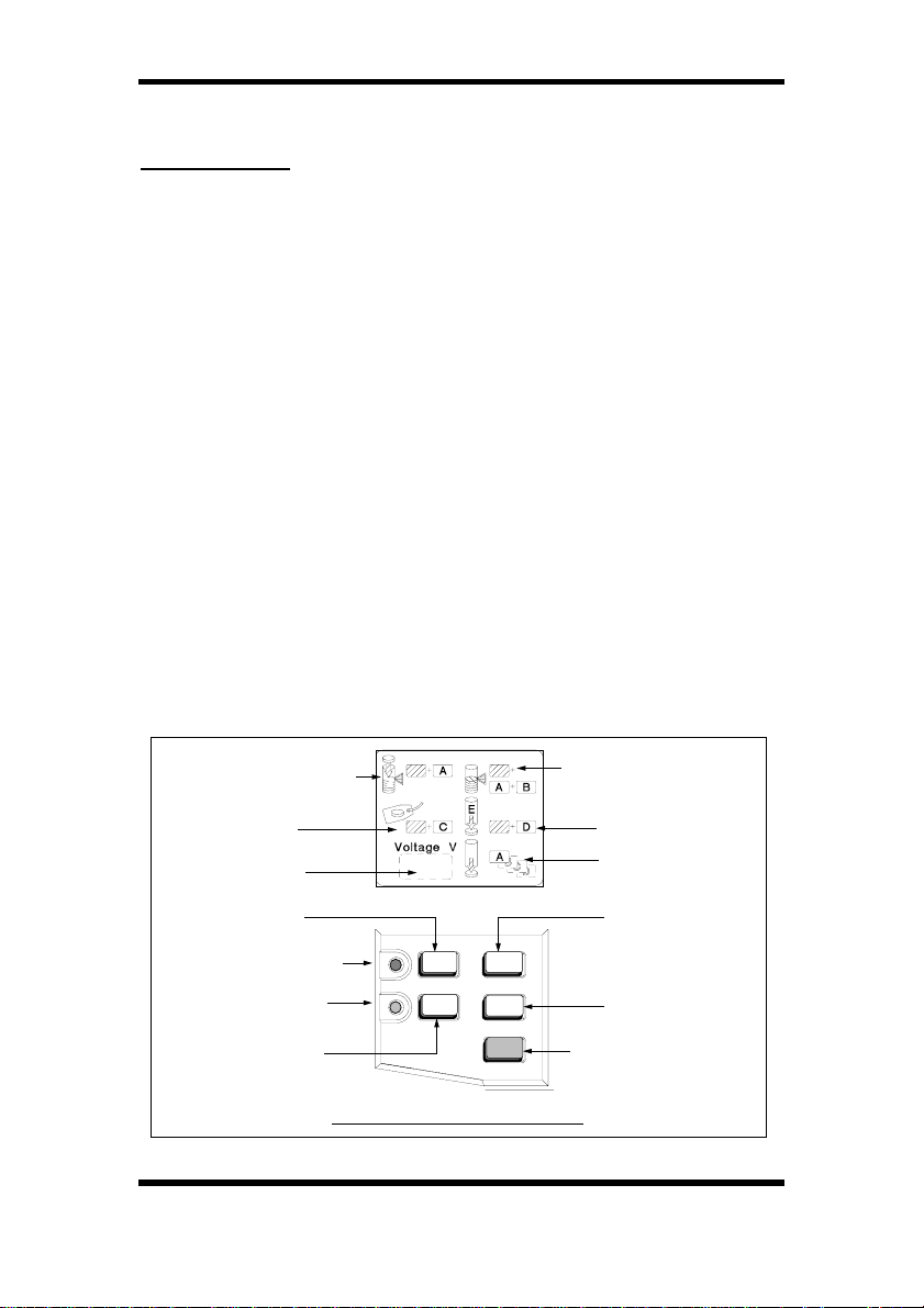
The keypad has four letter keys (blue) and a mode key (yellow).
There are two LEDs mounted on the left hand side of the keypad
(yellow and red) which are used to indicate the status of the
changegiver. Above the keypad is a label which has a window
showing the voltage. There are also pictures which identify the
modes of operation which are available using the keys.
Float up tube
Set vend
prices
Correct voltage
for unit
Tube A
dispense
Yellow LED
Red LED
Tube C
dispense
Keypad Label & Keypad
12 ©, MEI., 1997.
A B
C
Re-set tubes
automatically to
pre-set level
No function
Dispense
coins
Tube B
dispense
D
Tube D
dispense
Mode button
(YELLOW)

CashFlow 560 changegiver Product Maintenance Handbook
The keypad can be in either of two possible modes at any time normal or shifted. The keypad in normal mode allows you to
dispense coins while in shifted mode it allows you to change some
of the settings of the product.
The yellow LED is used to indicate what status the keypad is in. If
the LED is off then the keypad is in normal mode.
To change any of the functions using the keypad the changegiver
must be in an idle state, i.e. not vending or accepting coins, and the
keypad must be enabled It is possible that the keypad has been
disabled. To enable the keypad, use the MEI
terminal to alter address 244 value from a 1 to a 0.
When the mode key is pressed, the yellow LED starts to flash. This
indicates that the keypad is in shifted mode and you can change the
settings of the available functions using the keypad keys. If, after
pressing the mode key no other key is pressed within 10 seconds,
or if the mode key is pressed a second time, the keypad will return
to its normal mode and the yellow LED will go off.
The red LED is used to indicate the status of the system. Under
normal conditions the LED remains permanently on. If an error is
detected on the changegiver then the LED will flash. If a fault is
detected on the machine, i.e blocker, then the LED will be
permanently off.
Route Alpha 250
USING THE KEYPAD
Dispensing Coins
The tube positions in the coin storage cassette are labelled A,B,C,D
on the front of the plastic. When the same letter key on the keypad
is pressed a coin will be dispensed from the equivalent coin tube.
For instance if letter key A is pressed then a coin is dispensed from
the tube held in position A in the coin store.
On a single press-and-release of a key the changegiver will pay a
single coin from the tube. To get more than 1 coin from the tube hold
the key down and the changegiver will start dispensing coins
continually. If you release the key within 3 seconds of the initial
press, then dispensing will stop after the current coin is dispensed.
If the key is held for more than 3 seconds, dispensing will latch, and
releasing the key will have no effect. The dispenser will continue to
dispense coins until the tube reaches its safe coin level (minimum
number of 2 coins left in a tube), or any key is pressed. If 2 or more
keys are pressed at the same time, then the changegiver will pay
©, MEI., 1997. 13

CashFlow 560 changegiver Product Maintenance Handbook
coins from the selected tubes in the same way as described above.
Latched dispense will continue on each tube until each tube reaches
its safe coin level.
Setting Prices
The main principle of price teach is that selections will have their
prices set to the accumulated credit value. To use this mode:
1 Press the mode key on the keypad
2 Press key C. Any stored credit will be cleared and a
time-out period of 45 seconds will start. The time-out
period restarts after every accepted coin.
3 Enter coins through the acceptor until the value of the
price to be set has been reached. The value of any coins
entered will be accumulated as credit and will be
displayed on the credit display, if fitted.
4 Press the vend button on the machine corresponding to
the selection price. The price has now been set.
5 Press key C on the keypad to return to normal operation.
Coins to the value of the price set will be returned. If you
do not press the C key, then 45 seconds after the last
coin was entered, the unit will automatically return to
normal operation and credit will be returned.
The above stages can be repeated for any selection you wish to
change the price of. If a number of selections are required to be set
to the same price you only need to accumulate the credit value
once. You can then press the appropriate selection buttons on the
machine. If more than one price has to be set then accumulate the
lowest credit value first, set the price, and then add further coins to
the next highest value and set that price etc.
Note: Prices of 0 cannot be set.
On Executive and BDV variants, the prices are not normally held in
the changegiver and are therefore inaccessible to this form of
update unless price holding mode is enabled via the MEI
Alpha 250 Terminal, and the vending machine is able to support
price holding operation.
14 ©, MEI., 1997.
Route

CashFlow 560 changegiver Product Maintenance Handbook
Automatic Tube Float
To refill the coin tubes (float up) to their pre-programmed float levels
follow the instructions below.
1 Press the mode key on the keypad.
2 Press key A. Any stored credit will be cleared and a
time-out period of 45 seconds will start. The time-out
period restarts after every accepted coin.
3 Enter coins through the acceptor. The changegiver will
automatically accept only the amount of coins needed to
reach the required float level in that tube. Any
subsequent coins will be rejected. Any coins entered will
be accumulated as credit and will be displayed on the
credit display, if fitted.
4 Press key A on the keypad, it will clear any credit and
NOTE: When the tube is empty, the first coin may pass straight
through. If this occurs, remove the coin from the machine return cup
and put it back directly into the tube using the manual fill facility as
described earlier.
You can also reset the float levels using the MEI
terminal.
Coins can be filled above the pre-set float level in each tube outside
of the product. When the cassette is refitted and the dispense keys
are pressed, coins will stop dispensing when each tube reaches its
safe coin level. The changer can then be floated in the normal way.
return to normal operation.
Route Alpha 250
Automatic Tube Inventory
This function allows you to automatically dispense (i.e. float down)
all excess coins from each of the tubes. Change coins continue to
be routed to the tubes rather than the cashbox when the preset float
level has been reached.
1 Press the mode key.
2 Press key A followed by key C.
All coins above the preset float level will automatically dispense
from the tubes, and will stop when the pre-programmed float level
has been reached.
©, MEI., 1997. 15
CashFlow 560 changegiver Product Maintenance Handbook
Resetting the Tube Counts
You can force the tube counts to be set to their pre-programmed
float levels. This should be done if the coin storage cassette has
been manually filled to the preset float levels and then fitted to the
changer.
To avoid inadvertent resetting of the tube counts this function can
only be enabled if the changegiver is in the float mode.
1 Press the mode key.
2 Press key A followed by key B. The tube counts are now
reset to their pre-programmed float levels and the
changegiver exits the float mode.
Under no circumstances should the mode key and the A and B keys
be pressed if the low level sensor is uncovered.
Note: If the changegiver is not in the float mode before pressing the
reset key then the function will be ignored and the keypad will revert
to its normal mode.
Cancelling Credit
If you have been testing or resetting the changer outside of a shifted
mode you may accumulate credit in real money terms. To cancel
any credit, press the mode key once followed by the A key twice.
Key Pad Function Summary
= Mode key
Dispensing Coins
Setting Prices
Floating Tubes
Re-Setting Tube Counts
Automatic Tube Inventory
Resetting Dispenser Arms
Cancelling Credit
16 ©, MEI., 1997.
ABCD
or or or
C
+
A
+
+
+
A
A C
B
+
+
+
AA
++
CashFlow 560 changegiver Product Maintenance Handbook
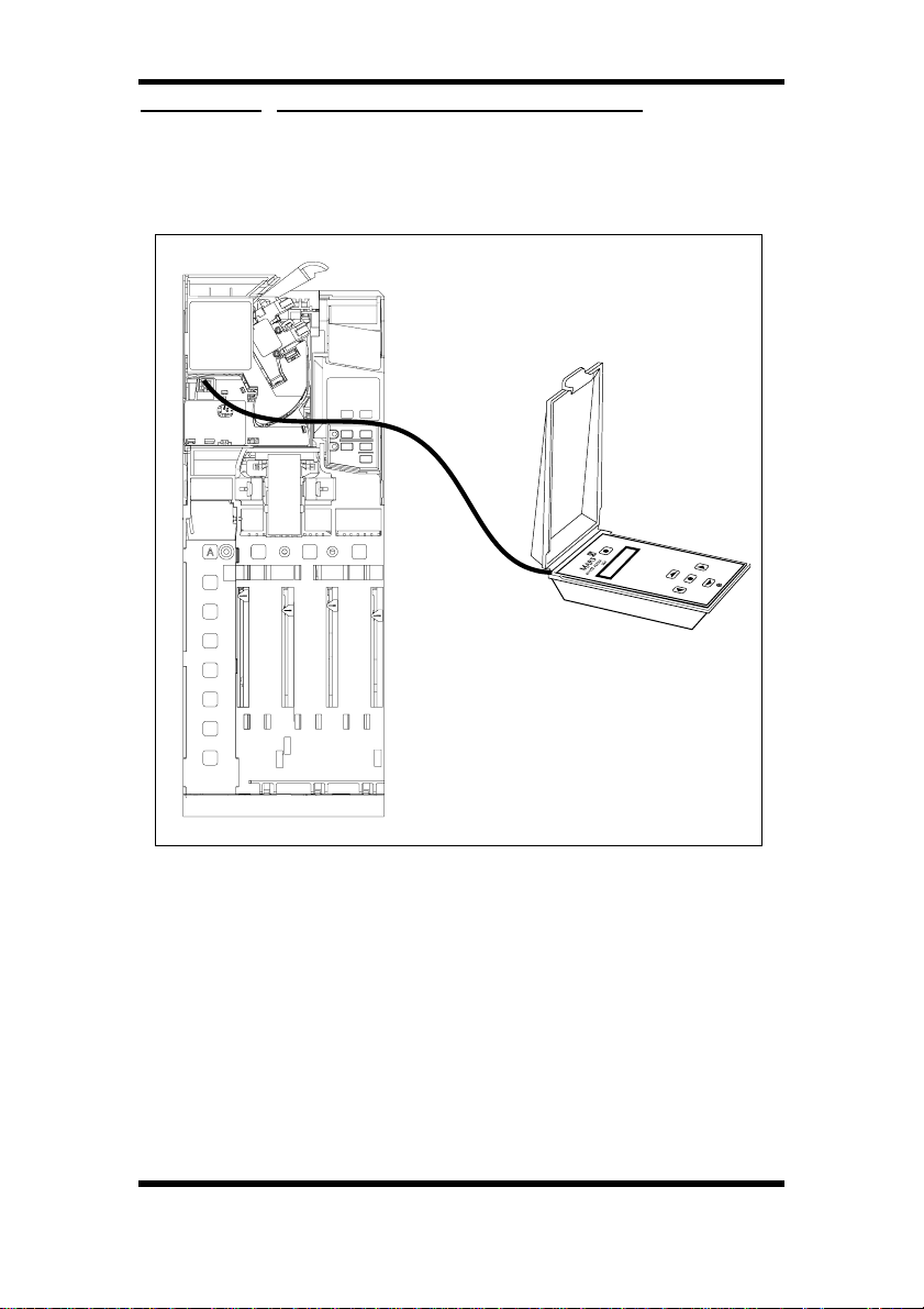
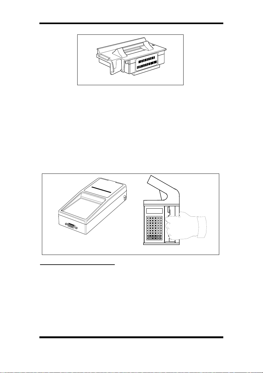
VIA MEI ROUTE ALPHA 250 TERMINAL
With a MEI Route Alpha 250 terminal you can re-configure any of
the functions available for a particular product. The terminal is
connected to the acceptor via a six way connector which plugs into
the front of the acceptor.
The terminal is used to check or change certain data which affects
the way the changegiver operates. The data is held in addresses.
Each address has a unique number which identifies the feature you
wish to read or change e.g. if you want to change from single vend
to multi vend then you need to go to address number 226 and put in
a 1 (single vend is a 0).
The following pages will explain how to access and change the data
in certain addresses. At the end of this section there is a list of
addresses and the relevant values. Particular reference should be
made to the symbols in this section which indicate the applications
(i.e. electromechanical, Executive, BDV and MDB) for which each
address is appropriate.
©, MEI., 1997. 17
CashFlow 560 changegiver Product Maintenance Handbook
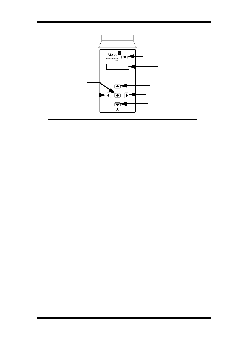
KEY FUNCTIONS
ENTER
LEFT
Reset Key: used to reset all modes and to initialise any settings that
you have changed. If the reset key is pressed while an address is
being updated then the address may not be updated. The reset key
must be pressed to store the changes that you have made.
Up Key: used to increase the value displayed on the screen.
Down Key: used to decrease the value displayed on the screen.
Left Key: used to scroll the display to the left when a large number
is being accessed that cannot be fully displayed on the screen.
Right Key: used to scroll the display to the right when a large
number is being accessed that cannot be fully displayed on the
screen.
Enter Key: used to change between the address and data displays.
Other Facilities of the Terminal
The terminal has several features to speed up its use. This includes
the ability to scan at a higher speed with the keys auto repeating, to
automatically roll over from its highest to lowest address and to
inform the operator should a communication error occur.
Should you need to know which version numbers of the software is
used in the changegiver the UP key is pressed while the terminal is
in reset mode. The terminal will firstly display the acceptor HI
address, if the UP key is pressed again the acceptor software
version number will be displayed. Pressing the UP key again will
display the acceptor eeprom number and if pressed again the
acceptor configuration code. Pressing the RIGHT key will display
the changegiver’s software number
To return to normal operation press the RESET key.
RESET
UP
RIGHT
DOWN
DISPLAY
2
node
18 ©, MEI., 1997.
CashFlow 560 changegiver Product Maintenance Handbook
Auto Repeating Keys
If either the UP or DOWN keys are kept pressed they automatically
repeat. The repeat speed of the key increases the longer the key is
held down.
Double Click Hotkeying
If a key is doubled clicked (pressed twice in quick succession) then
this causes the address number to increment by a larger amount.
e.g. if the user starts at address number 1 then double clicks the UP
key, the address will jump to 40, double click again the address will
jump to address 100 etc. This is useful as the addresses used for
the changegiver start at address 200. You can also double click the
DOWN key to decrement by larger amounts.
USING THE TERMINAL
As soon as the terminal is connected to a changegiver it powers up
and interrogates the product.
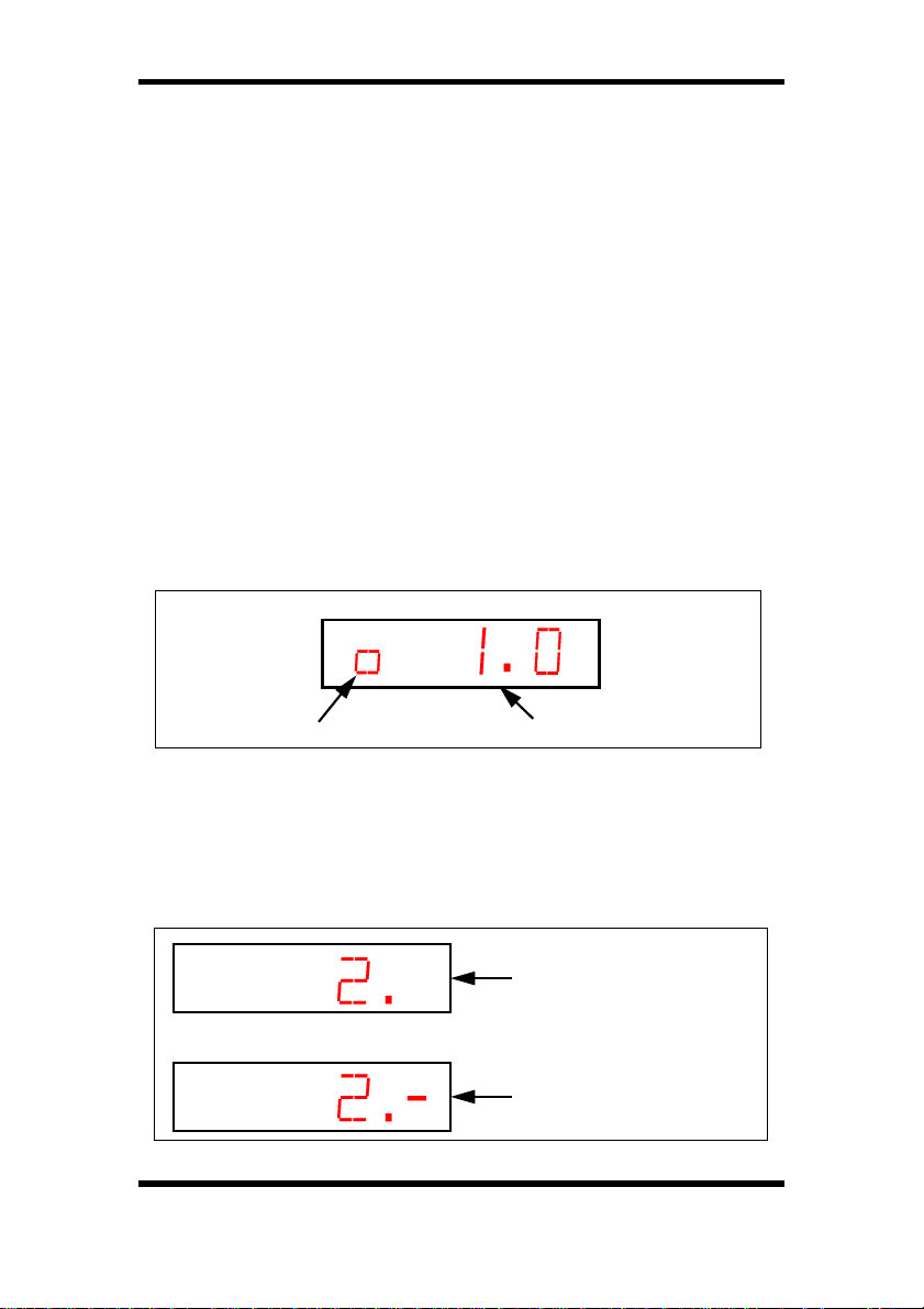
The terminal display will clear and briefly show a message that
indicates the version of software in the terminal. A display of [0 1.0]
means software with a version number of 1.0 is fitted in the terminal.
Power up message Software version = 1.0
After a few seconds the display will show the number [1.] or [1.-]. Not
all configuration items are applicable to every product but all the
address values are shown on the display. If the value for the
address is applicable to the product a dash will be present at the far
right position on the display. The value can then be accessed and
changed if required.
No dash displayed
Address is not accessible
for this product
Dash is displayed Address
is therefore accessible
©, MEI., 1997. 19
CashFlow 560 changegiver Product Maintenance Handbook
The basic operation to alter the information held in an address is:
1 Connect the terminal to the CashFlow
2 Wait for the terminal to power up correctly.
3 Select the address by using the UP and DOWN keys.
4 Examine the data by pressing the ENTER key.
5 Alter the data value by pressing the UP or DOWN keys
until the new value has been reached.
6 Press the ENTER key to return to displaying addresses.
7 Press the RESET key to initialise the new value.
When the terminal is displaying values stored at addresses, no
decimal point will be displayed.
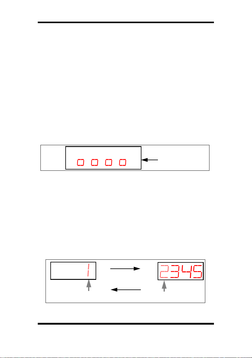
If an error occurs with the communication between the terminal and
the changegiver the display will show an error message of four half
height zeroes.
This message will stay on the display. Pressing the RESET key may
clear the fault. The display will then revert to showing the current
address. If the error occurred while updating an address then the
value of that address should be checked as it may not have been
updated correctly. If, after pressing the RESET key, the fault
remains the error message will stay and you need to return the
terminal for repair.
As the screen is capable of only displaying four digits at any one
time the number displayed on the screen can be scrolled if it is
greater than 9999 by using the LEFT and RIGHT keys. The left or
rightmost digit will flash indicating an extra digit can be examined by
use of the scrolling keys e.g. Value is 12345
press RIGHT key
product.
Error message
flashing
20 ©, MEI., 1997.
press LEFT key
flashing
CashFlow 560 changegiver Product Maintenance Handbook
VISUAL AUDIT
033330564
157847001 R1
Function Expansion Module
Visual Audit can be obtained, from the electro-mechanical and
Executive products only, when an audit function expansion module
(FEM) is installed as an accessory on to the Control PCB.
Data can be viewed with the use of a Route Alpha 250 terminal and
the process for using this method follows below. Data is also
available via a MEI
through an interface loom from the changegiver, through a DEX/
UCS jack-plug connected to a MEI
red optical interrogation point in the side of the machine, also using
the MEQ terminal.
®
hand-held printer which can be accessed
®
MEQ terminal, or from an infra-
®
Hand-Held Printer
MEI
MEI® MEQ Terminal
Visual Audit Interrogation
The Route Alpha 250 terminal display may not be able to show all
details for each address. In order to ensure that all data has been
read two quite separate addresses must be interrogated, one
consisting of the least significant (ls) digits, and the other the most
significant (ms) digits of the data.
To convert these two readings to a single audit value the (ms) value
shown must be multiplied by 65536 and the (ls) figure added to the
result.
©, MEI., 1997. 21

CashFlow 560 changegiver Product Maintenance Handbook
The following process should be followed to use the Route Alpha
250 terminal for retrieval of data:
• Firstly select the required address using the Up and
DOWN keys.
• Press ENTER to display the contents of the address. If
the value exceeds four digits the LEFT and RIGHT
keys are used to scroll the display left or right.
EXAMPLE. (To read the Cash In Tubes value)
• Select address 900
• Press ENTER to display the (ls) value, (e.g 54919)
• Press ENTER to return to address mode
• Press UP to select address 901
• Press ENTER to display the (ms) value, (e.g. 18)
• Multiply (ms) value by 65536 (18 x 65536 = 1179648)
and add (ls) value. (1179648 + 54919 = 1234567)
NOTES
All values are displayed on the terminal with no decimal point.
In order to reset the interim values address 999 must be used,
ensuring that it is set to 9.
All values displayed will be in the range of 0 - 65535.
The relevant addresses for the Route Aplha 250 terminal in the
following list are 900-999.
22 ©, MEI., 1997.

CashFlow 560 changegiver Product Maintenance Handbook
Route Alpha 250 Address Applications
The symbols below appear on the following pages together with
most of the following Route Alpha 250 address numbers. They can
be used as an aid to indicate which variety of product that each
address is used with.
Where no symbol is used this address applies to 4 price electromechanical products only.
✖ = Address used with 4 price and Executive only
✙ = Address used with 4 price, Executive and BDV only
▲ = Address used with 4 price, Executive, BDV and MDB
■ = Address used with 4 price and BDV only
✔ = Address used with Executive and BDV only
✸ = Address used with BDV only
◆ = Address used with MDB only
©, MEI., 1997. 23
CashFlow 560 changegiver Product Maintenance Handbook
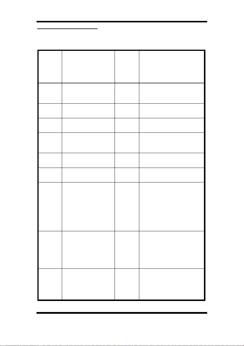
Addresses and Values
The table below shows you the address of each item that can be reconfigured and their possible values.
Address
✙
21 - 32
✙
200
✙
201-204
✖
205-225
✙
226
✙
227
228
▲
229
▲
230
Parameter
Coin types 1 - 12 0-2
Maximum credit 0-65,535
Prices 1 - 4 0-65,535 value of prices 1 - 4
Prices 5 - 25
(When audit FEM
fitted only)
Single/Multivend 0 -1
Escrow return inhibit 0 -1
Reset mode
(Electromech only)
Coin inhibit, coins 1-4
for multiple coin
inhibit,add together
e.g. 1 + 8 = 9 so coins
1 & 4 are inhibited
Coin inhibit, coins 5-8 0 -15
Range
0 = coin
1 = value token
2 = vend token
maximum credit 4 price,
maximum change BDV
0-65,535 value of prices 5 - 25
0 = single vend
1 = multivend
0 = escrow allowed
1 = escrow inhibited
0 = blocker reset
1 = delayed blocker reset
(30ms)
0 - 4
0 -15
2 = delayed blocker reset
(200ms)
3 = blocker hold reset
4 = after escrow accept
signal
0 = no coins inhibited
1 = inhibit coin 1
2 = inhibit coin 2
4 = inhibit coin 3
8 = inhibit coin 4
0 = no coins inhibited
1 = inhibit coin 5
2 = inhibit coin 6
4 = inhibit coin 7
8 = inhibit coin 8
Meaning
24 ©, MEI., 1997.