

Page 1
The
560
®
REFERENCE SERIES
CHANGEGIVER
APPLICATIONS DESIGN
GUIDE
CashFlow®CashFlow®CashFlow®CashFlow®CashFlow®Ca
shFlow
Flow
®
ow
®
CashFlow®CashFlow®CashFlow®CashFlow®CashFlow®C
ashFlow
hFlow
low
®
w
CashFlow®CashFlow®CashFlow®CashFlow®CashFlow
CashFlow®CashFlow®CashFlow®CashFlow®CashFlow®Ca
shFlow
Flow
®
ow
®
CashFlow®CashFlow®CashFlow®CashFlow®CashFlow®C
ashFlow
hFlow
low
®
w
CashFlow®CashFlow®CashFlow®CashFlow®CashFlow
CashFlow®CashFlow®CashFlow®CashFlow®CashFlow®Ca
shFlow
Flow
®
ow
®
CashFlow®CashFlow®CashFlow®CashFlow®CashFlow®C
ashFlow
hFlow
low
®
w
CashFlow®CashFlow®CashFlow®CashFlow®CashFlow
CashFlow®CashFlow®CashFlow®CashFlow®CashFlow®Ca
shFlow
Flow
®
ow
®
CashFlow®CashFlow®CashFlow®CashFlow®Cash
®
CashFlow®CashFlow®CashFlow®CashFlow®CashFl
CashFlow®CashFlow®CashFlow®CashFlow®CashFlow
®
CashFlow®CashFlow®CashFlow®CashFlow®Cas
®
CashFlow®CashFlow®CashFlow®CashFlow®CashF
®
CashFlow®CashFlow®CashFlow®CashFlow®CashFlo
®
CashFlow®CashFlow®CashFlow®CashFlow®Cash
®
CashFlow®CashFlow®CashFlow®CashFlow®CashFl
CashFlow®CashFlow®CashFlow®CashFlow®CashFlow
®
CashFlow®CashFlow®CashFlow®CashFlow®Cas
®
CashFlow®CashFlow®CashFlow®CashFlow®CashF
®
CashFlow®CashFlow®CashFlow®CashFlow®CashFlo
®
CashFlow®CashFlow®CashFlow®CashFlow®Cash
®
CashFlow®CashFlow®CashFlow®CashFlow®CashFl
CashFlow®CashFlow®CashFlow®CashFlow®CashFlow
®
CashFlow®CashFlow®CashFlow®CashFlow®Cas
®
CashFlow®CashFlow®CashFlow®CashFlow®CashF
®
CashFlow®CashFlow®CashFlow®CashFlow®CashFlo
®
CashFlow®CashFlow®CashFlow®CashFlow®Cash
®
CashFlow®CashFlow®CashFlow®CashFlow®CashFl
CashFlow®CashFlow®CashFlow®CashFlow®CashFlow
®
®
®
®
23174 G3 142922044
Page 2

CashFlow 560 changegiver Applications Design Guide
Published by :
Mars Electronics International
Eskdale Road
Winnersh Triangle
Wokingham, Berkshire RG41 5AQ
United Kingdom
For information on translations in your country, please write to the Technical Communications
Manager at the above address.
CashFlow560 changegiver Applications Design Guide
©, Mars, Inc., 1996.
All rights reserved.
Except as permitted under the relevant local legislation, no part of this publication may be
copied, transmitted, transcribed, or distributed in any form or by any means, or stored in a
database or retrieval system, or translated into any language (natural or computer), without the
prior written permission of Mars Electronics International.
Mars, CashFlow and the Mars Electronics International device are registered trademarks.
©, Mars, Inc., 1996.
Mars Electronics reserves the right to change the product or the product specifications at any
time. While every effort has been made to ensure that the information in this publication is
accurate, Mars Electronics disclaims any liability for any direct or indirect losses (howsoever
caused) arising out of use or reliance on this information.
This document does not necessarily imply product availability.
Part Number : 142922044
This Edition ( March 1996) Printed in the United Kingdom.
ii ©, Mars, Inc., 1996.
Page 3

CashFlow 560 changegiver Applications Design Guide
SAFETY.......................................................................................1
OVERVIEW.................................................................................2
PRODUCT OPERATION..........................................................5
GENERAL.............................................................................5
ELECTRO-MECHANICAL PRODUCT ........................5
SERIAL INTERFACE PRODUCTS..............................5
COIN ACCEPTANCE, ROUTING & RETURN ...................13
ACCEPTOR MODULE.................................................6
ACCEPT GATE MODULE ...........................................7
SEPARATOR ...............................................................7
CONTROL BOARD......................................................7
SPINE..........................................................................7
TRANSFORMER ASSEMBLY.....................................8
KEYPAD.......................................................................8
DISPENSER................................................................8
COIN STORAGE CASSETTE .....................................8
COIN ACCEPTANCE.................................................13
COIN ROUTING ........................................................14
CHANGE PAYBACK..................................................15
TUBE SENSOR USAGE............................................16
TABLE OF CONTENTS
Tube Combinations.............................................9
Exact Change Equation....................................10
Using Exact Change Inhibit ..............................12
Global Coin Inhibit ............................................14
Use of Tubes ....................................................15
Best Change Calculation..................................15
Full sensors ......................................................16
Coin cassette removal detection.......................17
Full sensor error detection................................18
Coin count re-calibration...................................18
Low sensor error detection...............................18
©, Mars, Inc., 1996. iii
Page 4

CashFlow 560 changegiver Applications Design Guide
PRODUCT INTERFACES......................................................21
ELECTRICAL INTERFACES..............................................22
ELECTRO MECHANICAL INTERFACE ............................25
EXACT CHANGE OUTPUT.......................................25
CREDIT RELAY DRIVE.............................................25
SAFETY LINE............................................................25
PRICE LINE COMMON.............................................25
PRICE LINE OUTPUTS.............................................25
MACHINE INTERFACE......................................................26
SINGLE / MULTI VEND .............................................27
SENSE INPUT TIMING .............................................27
VEND START ............................................................27
VEND FINISHED.......................................................28
BLOCKER RESET.....................................................28
DELAYED BLOCKER RESET ...................................29
BLOCKER HOLD RESET..........................................30
ESCROW ACCEPT...................................................31
PRICE SENSE / BLOCKER / ESCROW ACCEPT /
VEND START/ INHIBIT INPUTS................................32
Coin count re-calibration...................................19
Home sensors...................................................20
EXTERNAL CREDIT DISPLAY ..........................................33
DISPLAYING CREDIT ...............................................33
CANCELLING CREDIT..............................................33
DISPLAYING VEND PRICE.......................................34
DISPLAYING PRICE TEACH CREDIT......................34
DISPLAYING FLOAT VALUE.....................................34
POWER ON INDICATOR...........................................34
DISPLAYING TUBE VALUE ......................................34
VOLTAGE RANGES ..................................................35
POWER CONSUMPTION / RATING.........................35
TERMINAL CONNECTOR..................................................35
MAN MACHINE INTERFACES ..........................................36
KEYPAD.....................................................................36
LED Usage .......................................................37
Manual Coin Dispense......................................37
Automatic Tube Float (Float Up).......................38
iv ©, Mars, Inc., 1996.
Page 5

CashFlow 560 changegiver Applications Design Guide
INTERNAL DIAGNOSTICS & ERROR HANDLING ..........41
HOST MACHINE PROBLEMS ..................................41
COIN HANDLING PROBLEMS .................................43
ON-BOARD EEPROM PROBLEMS..........................44
AUDIT FEM PROBLEMS...........................................46
HOST INTELLIGENT INTERFACE(HI2) ERRORS ...46
MISCELLANEOUS ERRORS....................................47
VIA MARS
KEY FUNCTIONS......................................................49
USING THE TERMINAL............................................50
VISUAL AUDIT..........................................................52
DIAGNOSING TERMINAL PROBLEMS ...................64
Float Down Mode..............................................39
Resetting Tube Counts.....................................39
Price Teach ......................................................39
Homing the Dispensers ....................................40
Displaying Tube Value......................................40
Host Inhibited....................................................41
Removal of Blocker...........................................41
Blocker Return..................................................42
Cashbox Full.....................................................42
Bad Replies Received ......................................42
No Response....................................................43
Full Sensor Failure............................................43
Post Gate Strobe (PGS) Failure.......................43
Tube Cassette Removal...................................43
Home Sensor Failure........................................44
Motor Failure / Jam...........................................44
Incorrect Configuration vsn. No........................44
EEPROM Corruption ........................................45
Write Timeout ...................................................45
Audit not initialised............................................46
Audit FEM corrupt.............................................46
Audit removed ..................................................46
HI2 Error...........................................................46
Acceptor Initialising Error..................................47
ROUTE ALPHA 250 TERMINAL...................48
Visual Audit Interrogation..................................52
Testing the Terminal.........................................65
©, Mars, Inc., 1996. v
Page 6

CashFlow 560 changegiver Applications Design Guide
ENVIRONMENTAL PERFORMANCE.................................66
TEMPERATURE RANGE...................................................66
HUMIDITY...........................................................................66
VIBRATION.........................................................................66
INSTALLATION ..................................................................66
TRANSPORTATION...........................................................67
LIQUIDS..............................................................................67
VOLTAGE ...........................................................................68
VOLTAGE TRANSIENTS ...................................................68
SAFETY CLASSIFICATIONS...............................................69
CLASSIFICATION ..............................................................69
PARTITIONS.......................................................................69
SAFETY INSULATION .......................................................70
ENERGY STORAGE..........................................................70
FLAMMABILITY.................................................................70
ELECTRO-MECHANICAL AND MAINS INPUT RATINGS71
MECHANICAL PARTS.......................................................71
COMPATIBILITY......................................................................72
BILL VALIDATOR INTERFACE .........................................74
MARS ELECTRONICS INTERNATIONAL OFFICES .....78
INDEX.........................................................................................79
APPENDIX ................................................................................84
INTERFACE DRAWING .....................................................84
vi ©, Mars, Inc., 1996.
Page 7

CashFlow 560 changegiver Applications Design Guide
SAFETY
International & National Standards
Conformance
When installed and operated according to the
instructions for the particular unit, CashFlow
products are designed to meet the applicable
Safety and Electro Mechanical Conformance
standards for any country in which they are used.
CashFlow
construction. No safety earth connection is
necessary or provided.
560 products are of class II
560
Dangerous Environments
Do not operate in the presence of flammable
gases, fumes or water.
Disposal of Product
Do not dispose of any parts of this product by
incineration.
Rated Operating Voltage
The rated voltage is indicated on a clear see
through label above the changegiver keypad.
Always operate the changegiver from the type of
power source indicated on the label.
Warning: before removing or replacing modules
SWITCH OFF or ISOLATE the ELECTRICITY
SUPPLY to the host machine
THIS MANUAL IS PROVIDED FOR USE ONLY BY PERSONNEL
TRAINED TO UNDERTAKE ELECTRICAL INSTALLATION
©, Mars, Inc., 1996. 1
Page 8
CashFlow 560 changegiver Applications Design Guide
OVERVIEW
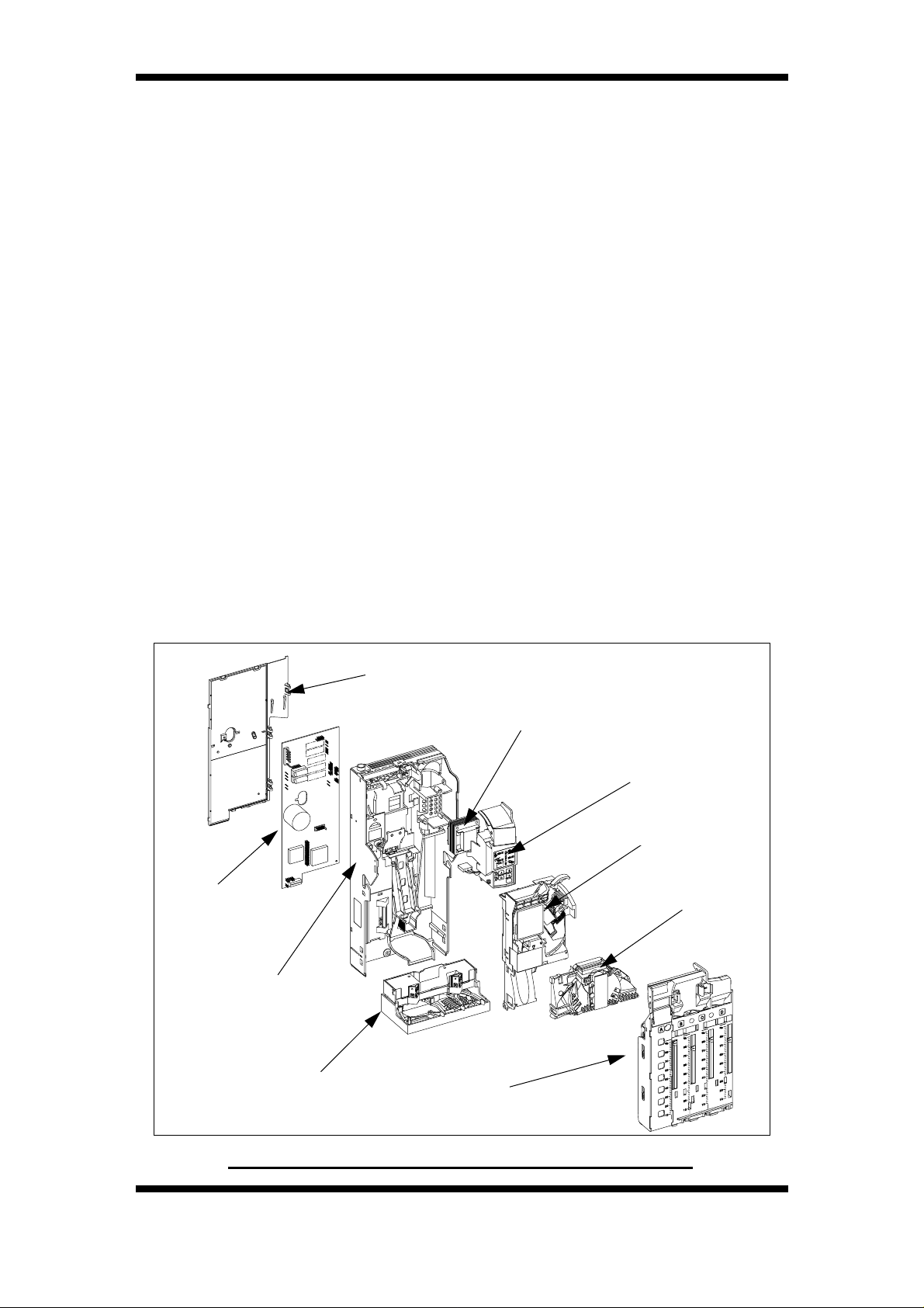
The CashFlow 560 range of changegivers have been designed to
address a wide range of market needs and are compatible with the
majority of modern vending machines. They are plug compatible
replacements for the previous MS1600, ME1600 and ME1900
series of changegivers. The flexible approach allows easy matching
of modules for all types of applications. They are designed to work
with a wide range of coinsets and can be upgraded to accept new
coins. There are four change tubes and field selection of the coins
to be stored in them is possible. On the front of the changegiver is a
keypad which is used to dispense coins and re-configure some
aspects of the changer. All CashFlow
up of several modules;
• Control board
• Spine
• Transformer
• Keypad
• Dispenser
• Acceptor
• Separator
• Coin Storage Cassette
560 changegivers are made
Control Board
Spine
Dispenser
Back Cover
Transformer
Keypad
Acceptor
Separator
Coin Storage Cassette
Exploded View of the CashFlow Changegiver
2 ©, Mars, Inc., 1996.
Page 9

CashFlow 560 changegiver Applications Design Guide
The basic functionality of all changegivers is to:
The following function is appropriate for electro-mechanical 4-price
product only:
The following functions are appropriate for electro-mechanical 4price, Executive and BDV product only:
• Accept payment
• Signal the payment available to the machine (credit
output)
• Monitor the product request inputs (sense inputs)
• Return un-used change
• Monitor the machine inhibited condition (blocker)
• Enable the appropriate price line output (if the vend is
authorised)
• Deduct the vend price from the credit available
• Indicate to the host machine the exact change
condition
The product options currently available are;
• CashFlow
mechanical changegiver
N.B. A credit display for use with the above variant can be provided.
• CashFlow
electronic Protocol A serial interface
• CashFlow
BDV serial interface
• CashFlow
MDB serial interface
560 - 4 price - A four price electro-
560 - Executive - changegiver with an
560 - BDV - changegiver with an electronic
560 - MDB - changegiver with an electronic
©, Mars, Inc., 1996. 3
Page 10

CashFlow 560 changegiver Applications Design Guide
With the use of the Mars Route Alpha 250 terminal you can also
re-configure certain operational aspects of the changegiver. This
includes inhibiting coins, changing from single to multi vend etc..
®
The CashFlow
be supplied with an audit fuction extension module (FEM) fitted, or
this can be supplied for fitting at a later date.
The FEM allows for reports to be supplied either via a hand-held
Mars
These reports can include:
Audit 920 printer, or down-loaded via a terminal to a P.C..
560 electro-mechanical and Executive products can
• Value of cash manually filled
• Value of cash retained in the changegiver
• Value of cash sales
• Value of token sales
• Value of cash taken by the machine
• Value of cash to cashbox
• Value of cash dispensed as change
The process of obtaining data is detailed in the section of this book
concerned with the Mars
For further details of audit installation please refer to the Mars
900 Installation Guide, part number 143451999.
Additional information on the audit FEM and the Mars
printer can be obtained from your MEI regional office.
Route Alpha 250 terminal.
®
Audit
Audit 920
4 ©, Mars, Inc., 1996.
Page 11

CashFlow 560 changegiver Applications Design Guide
PRODUCT OPERATION
GENERAL
ELECTRO-MECHANICAL PRODUCT
When a coin is entered through the electro-mechanical changegiver
there are several conditions that are electronically checked.
After coins have been accepted and a product selection button is
pressed a sense current flows through the changegivers sense
circuit. The sense current is not sufficient to energise the relay, but
enough for the changegiver to detect. When the changegiver
detects that a product selection button has been pressed the
changegiver looks up the price associated with the selection. If
sufficient credit exists the changegiver turns the price line output on.
This disconnects the safety line from price line common and
connects the price line output to price line common. The vend motor
relay within the vending machine is then energised, turning the vend
motor on and closing a switch across the selection button.
When the vend cycle begins the blocker signal indicates to the
changegiver that a vend has started. The price of the vend is
deducted and the changegiver waits for the vend to finish. The price
line output is turned off when the changegiver considers the vend to
have finished.
Unused credit may be returned after the vend has finished either
automatically if in single vend mode, or by customer demand if it is
in multi vend mode, or after a pre-determined time in multi-vend
option setting, depending on how the changegiver has been set up.
SERIAL INTERFACE PRODUCTS
Dependent on which version of product is being used , when coins
or cashless card are inserted the value involved will be shown on the
display, if used. The host machine’s VMC communicates all
functions as required with the changegiver and any other
peripherals, such as an audit unit or cashless payment system, that
are being used.
The VMC in the host machine produces signals to the changegiver
(excluding MDB product) indicating when a vend is to be made, and
the value of the vend required. The changegiver will then ascertain
if sufficient credit is available to cover the cost of the vend. If the
changegiver is set to “No Overpay” it will confirm that any remaining
coin credit that would result from the vend can be returned before
authorising the vend.
©, Mars, Inc., 1996. 5
Page 12
CashFlow 560 changegiver Applications Design Guide
If the vend is allowed the cost will be deducted from the credit prior
to authorising the VMC to start the vend. Should the vend fail, this
credit will be re-instated.
ACCEPTOR MODULE
There are some functions of the acceptor module which are
common across the whole CashFlow
include coin discrimination, control and communication.
When a coin is put through the acceptor module it’s validity is
determined by measuring certain parameters. It also looks at the
coin type status to define whether the payment is a valid coin or
token, or an invalid coin. Finally, the inhibit status is checked. If the
coin is not inhibited, then it will be accepted, the accept gate
opened, and the coin routed to either a tube or cashbox. The
acceptor module is made up of the discriminator, back cover and the
accept gate.
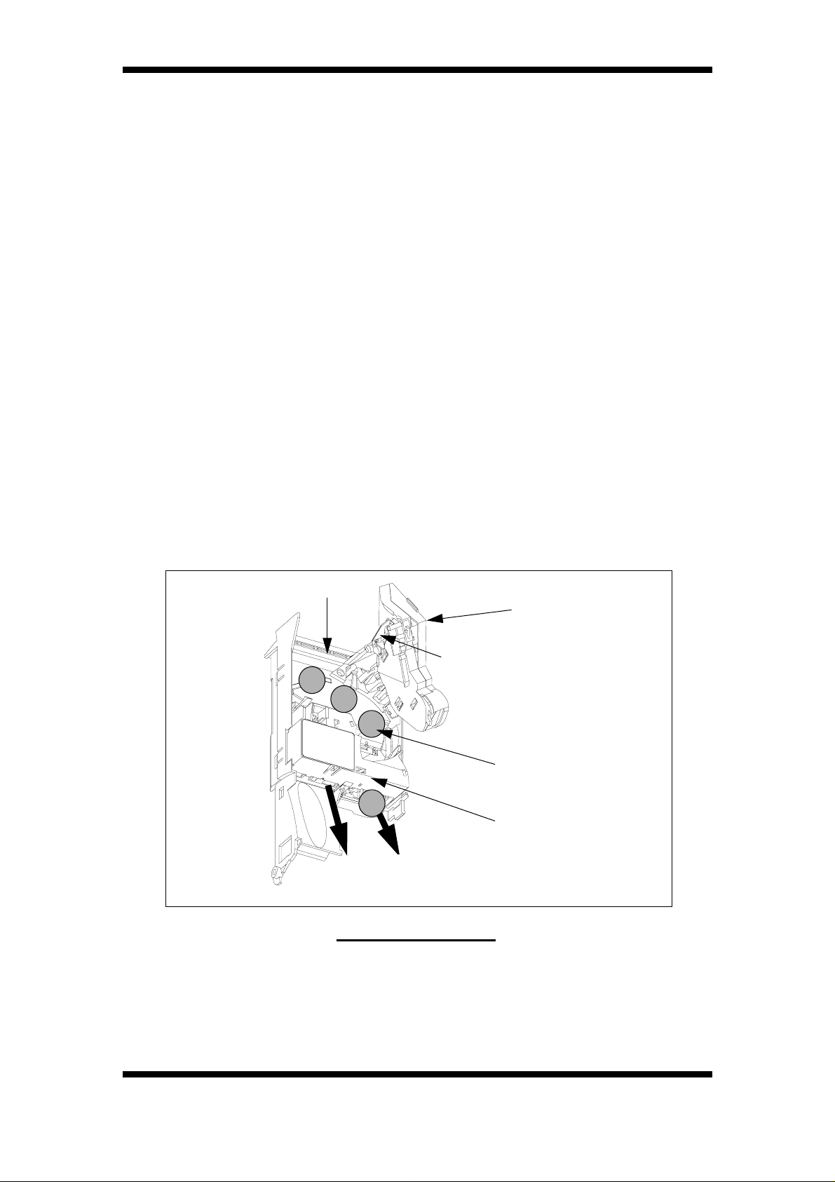
The discriminator comprises a flight deck and lid which together
form the coin control and flight path. On the inside of the flight deck
lid there is a mechanical device incorporated near the coin entry
point. This device is known as the coin deflector and is used to bring
coins under control as they enter the product
product range. These
Flight Deck
Coin Deflector
Reject
Route
Acceptor Module
A hinge at the top right hand side of the flight deck allows coupling
of the lid via an intermediate component, known as the lid arm. This
allows the lid to locate accurately to the flight deck independently of
the hinge. The lid also maintains a parallel coin throat by being
Accept
Route
Flight Deck
Lid
Coin Path
Accept Gate
Module
6 ©, Mars, Inc., 1996.
Page 13

CashFlow 560 changegiver Applications Design Guide
spaced from the deck on three bosses which locate the lid squarely
to the deck.
The design of the lid arm hinge area allows the lid to open to 180
degrees relative to the deck. The opening is restricted to just over
100 degrees by the back cover to prevent the lid possibly fouling
other parts.
The action of the hinge spring allows the lid to remain open when
past about 100 deg. and will snap shut when closed to about 60
degrees although the lid will need to be pressed to ensure that it is
correctly seated against the deck. The acceptor module connects to
the control board via a 10 way ribbon cable.
On the front of the acceptor module there is a six way socket. This
is for use with a Mars
hand held and, when connected to the acceptor, allows some of the
operational aspects of the changegiver to be altered.
Route Alpha 250 terminal. The terminal is
ACCEPT GATE MODULE
The accept gate module contains a solenoid operated gate, optical
coin strobes and coin routing components. Coins that are correctly
discriminated are routed to the accept exit by energising the accept
gate. Coins that are rejected are routed to the reject exit.
SEPARATOR
The separator separates the coins into different routes, either to the
coin storage tubes or the cashbox. It contains a solenoid bank and,
at the bottom, a top level sensor assembly which is used to avoid
tube overflow.
CONTROL BOARD
This is the main PCB which controls the way in which the
changegiver operates. There are several different control boards,
but basically these are the 4 price for electromechanical machines,
and the Executive, MDB and BDV for electronic machines.
SPINE
The spine provides the housing for all of the other modules. On the
rear of the spine are the three standard keyhole fixing points for
fitting the changegiver into a machine.
©, Mars, Inc., 1996. 7
Page 14

CashFlow 560 changegiver Applications Design Guide
TRANSFORMER ASSEMBLY
The transformer assembly is housed behind the keypad cover. To
gain access to the transformer there is a screw located under the top
flap of the keypad cover. Once this screw has been removed the
keypad cover will lift off and the transformer is accessible. The
transformer connects to the control board via two looms and is
available in 24V, 100V, 120V, 220V, and 240V options.
Note: On CashFlow
transformer is replaced by a reservoir capacitor.
KEYPAD
The keypad is used to float or dispense coins and to re-configure
some aspects of the way in which the changegiver works.
DISPENSER
The dispenser is held in the spine by two clips, one on each side. It
connects to the control board via a loom. It contains four dispense
arms which, when operational, dispense coins from each of the four
storage tubes. The dispenser also contains low level sensors which
detect when the coin tubes are low on coins. It is possible to
dispense coins from more than one tube at the same time.
560 BDV and MDB changegivers the
COIN STORAGE CASSETTE
The coin storage cassette clips to the front of the changegiver and
contains four independent coin storage tubes. There are thirteen
different sizes of tube, each numbered from 0 - 7. These cover most
sizes of coins that you should want to route to coin tubes.
N.B. Some have a suffix of “.5” (i.e. 2.5), and dimensions range from
0 which has the largest bore and 7 with the smallest bore. Each tube
has a designator fitted at the bottom. The size of the designator
fitted is dependant upon the thickness of the coin. There are eight
different sizes of designator each lettered from A - H.
The front cover is marked A,B,C,D to indicate the position of the
fitted tube, as shown below. Coins of the following sizes can fit into
each of the positions:
• Coin diameters from 15.0 to 26.0 mm in position A
• Coin diameters from 18.6 to 32.5 mm in position B
• Coin diameters from 15.0 to 29.2 mm in position C
• Coin diameters from 18.6 to 29.2 mm in position D
8 ©, Mars, Inc., 1996.
Page 15
CashFlow 560 changegiver Applications Design Guide
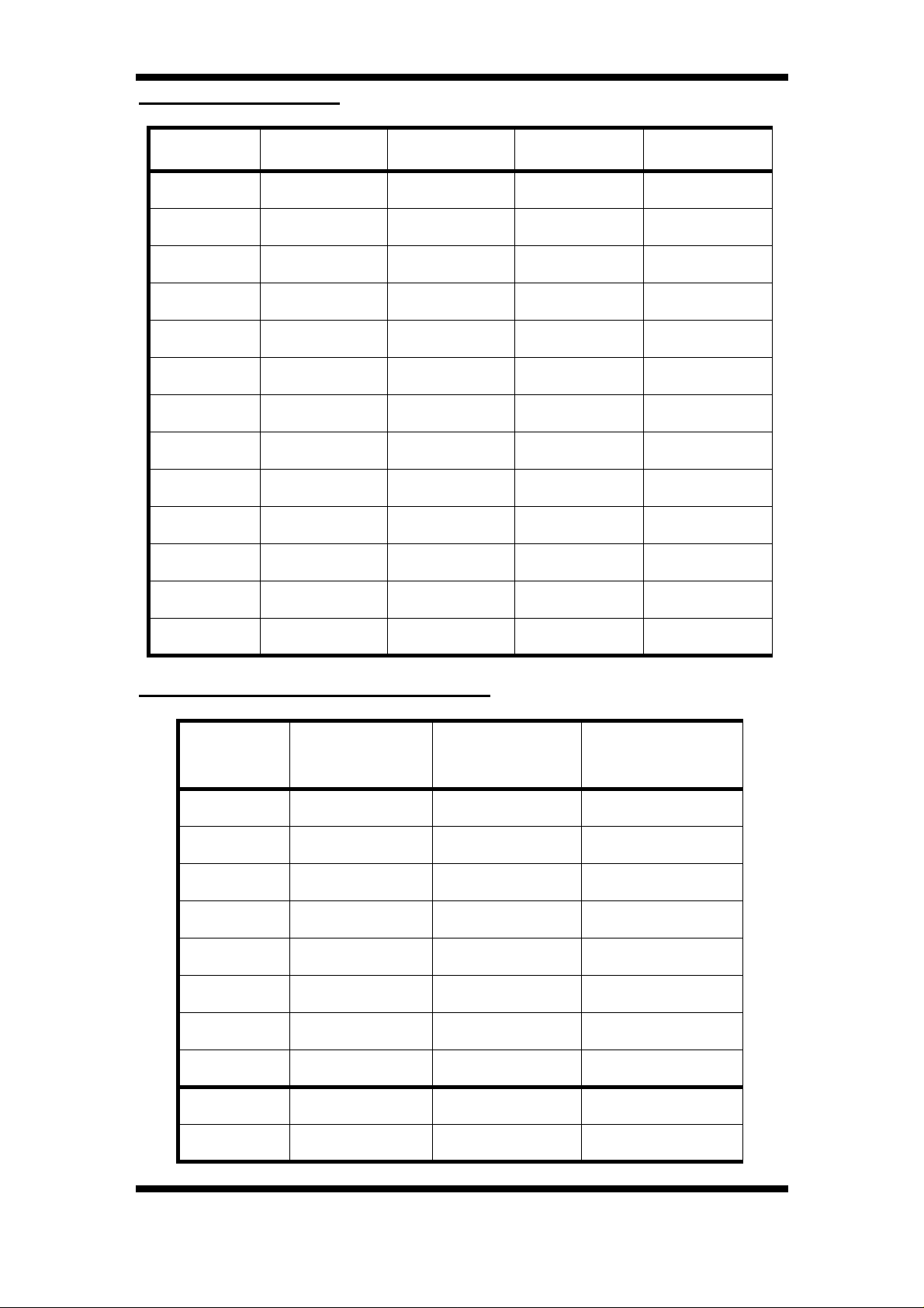
Tube Combinations
Tube Position A Position B Position C Position D
0
1
2
2.5
3
3.5
4
4.5
5
5.5
6
6.5
7
✘✔✘✘
✘✔✘✘
✘✔✔✔
✘✔✔✔
✘✔✔✔
✔✔✔✔
✔✔✔✔
✔✔✔✔
✔✔✔✘
✔✔✔✘
✔✘✔✘
✔✘✔✘
✔✘✔✘
COIN SIZES FOR EACH TUBE
Tube No Part No
0 101812001 31.01 32.50
1 140164001 29.21 31.00
2 101825001 26.91 29.20
2.5 169494001 26.01 26.90
3 101838001 24.51 26.00
3.5 169509001 23.21 24.50
4 101841001 21.61 23.20
4.5 169512001 20.76 21.60
5 101854001 19.51 20.75
Min Coin
Diameter
Max Coin
Diameter
5.5 169525001 18.61 19.50
©, Mars, Inc., 1996. 9
Page 16

CashFlow 560 changegiver Applications Design Guide
Tube No Part No
6 101867001 18.11 18.60
6.5 169538001 16.70 18.10
7 101870001 15.00 16.69
Although there are different sizes of tubes and designators
available, not every tube can be fitted into every position in the
cassette.
There are prisms located at the top of each tube which, when
combined with the optos on the separator form the top level sensor.
The top level sensors are used to indicate when a tube is full. When
a tube is full any further coins are routed to the cashbox.
The cassette can be automatically filled by feeding coins through
the product, or manually filled by removing the cassette from the
changegiver.
Min Coin
Diameter
Max Coin
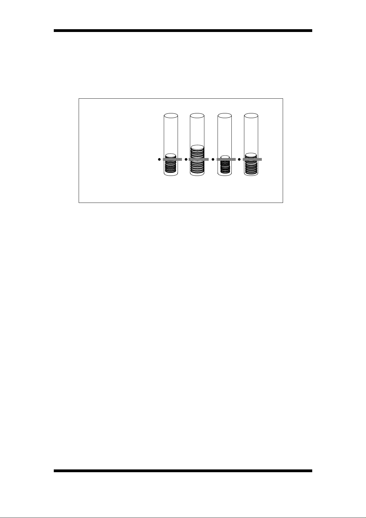
Diameter
On the front of the cassette are float indicators which you can
position manually by sliding up and down.
Exact Change Equation
When the changegiver, other than MDB product, detects that the
quantity of coins in a coin tube is below the low-level sensor, a
signal is sent to the vending machine to switch on the exact change
light (ECL) so as not to risk short-changing a customer.
Setting the exact change equation ensures that the optimum
combinations of change coins are always dispensed, by using
coins from alternative tubes to make up the change required, and
that the ECL is on for the minimum time possible.
An explanation of the process used to determine the optimum coins
for change can be found later under the heading of Best Change
Calculation.
Two exact change equations can be set using Route Alpha 250
terminal, addresses 236 and 237. The tubes A, B, C and D are
coded 1, 2, 4 and 8
Address 236 = exact change equation, part 1 - offers the first option
to use change coins from nominated tubes .
10 ©, Mars, Inc., 1996.
Page 17
CashFlow 560 changegiver Applications Design Guide
Address 237 = exact change equation, part 2 - sets a second
selection of change tubes.
Address 383 can also be used, with BDV product only, to give an
additional early warning setting, (in conjunction with addresses
271-274), and trigger the ECL to come on at an earlier point when
the coin count in a selected tube becomes low coded 1, 2, 4, and 8.
1p 2p 5p 10p
Low-level sensor
Tube
AB D
12 48Code
C
EXAMPLE: A four-tube changegiver contains 1p, 2p, 5p and 10p
coins, and the vend price is 16p.
If 20p is inserted, the optimum change payout will be from tubes A
and B. Therefore address 236 - exact change equation, part 1must be set to 3 (using code 1 + code 2 to equal 3). This setting will
ensure that the ECL comes on when tubes A and B become low.
If 50p is inserted, the optimum change payout will be from tubes A,
B AND D. Thus address 237 - exact change, equation part 2- must
be set to 11( using codes 1 + 2 + 8 to equal 11. This setting will
ensure that the ECL comes on when tubes A, B and C become low.
Setting both addresses 236 and 237 will cause the ECL to come on
when tubes A and B, or tubes A, B and C become low.
If the vending machine becomes inhibited (blocked) this is signalled
to the changegiver by the blocker signal. During the inhibited state,
coin acceptance is disabled. This condition may occur because
there are no products left in the machine, or the machine has
developed a fault.
©, Mars, Inc., 1996. 11
Page 18

CashFlow 560 changegiver Applications Design Guide
Using Exact Change Inhibit
When the machine is in exact change mode, selected coins can be
inhibited, other than with MDB product.
Setting the exact change inhibit option will stop a specified coin or
coins being accepted when the exact change light is on. It is usual
to inhibit the highest value coin(s) to minimise the risk of the
customer being short-changed.
When the coin level rises again above the low count, the ECL is
turned off, and the inhibit option switched off so that the previously
inhibited coins are accepted.
The coin set for the unit is divided into three exact change groups,
in which each coin has a code. The groups are associated with
addresses 232, 233 or 234. Set the range value of the addresses to
the code of the coin you want to inhibit. Add the codes together to
inhibit more than one coin at a time in each group.
Addresses 232 - coins 1 - 4 using codes 1, 2, 4 and 8
Addresses 233 - coins 5 - 8 using codes 1, 2, 4 and 8
Addresses 234 - coins 9 - 12 using codes 1, 2, 4 and 8
12 ©, Mars, Inc., 1996.
Page 19

CashFlow 560 changegiver Applications Design Guide
COIN ACCEPTANCE, ROUTING & RETURN
The changegiver has a standard coin entry and exit chuting. Coin
return via a reject lever is also standard. The coin acceptance, and
the routing used on coin acceptance, are dependant on:
• The set up of various configuration items in the
changegiver EEPROM
• Other changegiver conditions which will alter while the
changegiver is in operation
As a result of this, both coin acceptance and coin routing are
dynamic, i.e. changing in time as the state of the changegiver alters.
The dependencies are detailed in the following sections.
COIN ACCEPTANCE
The acceptance of each coin is determined primarily by the set up
of default inhibits in the EEPROM. This specifies which coins should
always be inhibited (i.e. rejected). In addition to these defaults, extra
inhibits will be imposed depending on the following conditions:
In normal mode with the overpay inhibit flag set:
• Coins which are not dynamically routed to the tubes will
be inhibited and rejected if their value, plus the existing
coin credit, cannot be returned due to lack of correct
change coins
• Coins which would take the total system credit over the
maximum allowed credit are inhibited
• Vend tokens are inhibited if the total system credit is
not zero
In normal mode with the overpay inhibit flag clear:
The Vending Machine Contoller (VMC) overules this in the MDB
product
• If use exact change has been signalled, the exact
change inhibits are imposed
• Coins which would take the total system credit over the
maximum allowed credit are inhibited
• Vend tokens are inhibited if the total system credit is
not zero
In float mode:
• All coins which are not dynamically routed to the tubes
will be inhibited
In price teach mode:
• Coins which would take the total system credit over the
maximum allowed credit are inhibited
• Vend tokens are inhibited
©, Mars, Inc., 1996. 13
Page 20

CashFlow 560 changegiver Applications Design Guide
Global Coin Inhibit
In addition to the individual coin inhibits described above, a global
coin inhibit can be imposed. This will inhibit all coin acceptance
regardless of any other conditions. A global inhibit is imposed when:
• Manually dispensing coins either from the key pad or
the terminal
• Returning credit
• A vend is in progress (VMC function on MDB)
• A price is on the display due to a product selection
being made with insufficient credit. (When in price
display mode). (Not on MDB)
• Value of tube contents is on the display. (Not MDB)
• Any bits in the EEPROM error register are set, apart
from code 5
• A free vend token has been accepted
• An executive type vending machine has indicated that
it requires a free vend
• The host machine has indicated it is inhibited
• The cashbox error code or if the protocol A error code
is set
• The blocker signal is not present
COIN ROUTING
The coin routing used is determined in the EEPROM. If a tube is not
®
fitted this is indicated as 00 on the Mars
display. In addition, there are conditions which prevent coin routing
to a tube even when it does store the coin. These are any of the
following:
• The tube full sensor reads covered (or has failed its
self-test, if test enabled on acceptor)
• There was a fatal dispenser error on that tube
• The tube counts held in changegiver RAM are equal
to, or greater than, the maximum level for that tube.
The routes, determined by all the above criteria, are the dynamic
routes. Before a coin can be routed it must first be accepted. If a coin
is rejected none of the above applies.
Route Alpha 250 terminal
14 ©, Mars, Inc., 1996.
Page 21

CashFlow 560 changegiver Applications Design Guide
CHANGE PAYBACK
In general the changegiver will attempt to return any coin credit to
the consumer, in the best possible coin mix. However, this simple
statement requires clarification.
Use of Tubes
• The changegiver will only attempt to use tubes which
are shown as fitted, and have not been disabled by the
occurrence of sensor or dispenser faults
• If a tube is fitted and is not disabled, it will be allowed to
be used for change payback only if its tube counts are
above the safe count value at the start of the change
payback sequence
• The changegiver will not function if the coin storage
cassette is not fitted
Best Change Calculation
Once the tubes that can be used have been determined the best
coin mix to pay back the change is calculated. Best coin mix is
defined as the first of the following found to be possible:
• Correct change paid with minimum number of coins
• Correct change paid with non-optimal coin mix
• Closest change paid with minimum number of coins
• Closest change paid with non-optimal coin mix
• No change paid
Once the best coin mix has been determined the dispensers will
start to pay the change out. The software will drive as many motors
as possible at once to expedite the change payback. (Not MDB)
Should either of the following occur the dispense sequence will be
suspended once each motor has got to its home position:
• The tube has run out of coins while coins are still
required. This could occur if the low level sensor/s go
from covered to uncovered, causing a tube count
recalibration, which reduced the number of coins held
in the tube. (Not MDB)
• A dispenser error is detected (stall, etc.)
The software will then re-compute the best coin mix to pay back the
credit still remaining and re-start the dispensers with this new coin
mix. The above will be repeated until all the change which can be
dispensed has been paid.
©, Mars, Inc., 1996. 15
Page 22

CashFlow 560 changegiver Applications Design Guide
TUBE SENSOR USAGE
This section describes the operation of the tube sensors in more
detail. The sensor operation significantly affects the users
perception of how the changegiver appears to operate.
Each tube has associated with it three sensors:
• The full level sensor (opto sensor)
• The low level sensor (opto sensor)
• The tube dispenser home position sensor (reed switch)
Full sensors
Effect on coin routing
The changegiver cannot read the tube full sensors directly, but must
request their status from the acceptor module. The acceptor module
then performs a self-test of the full sensors. The acceptor module
reports both the reading of the sensor, covered or uncovered, and
the outcome of the self-test, OK or failed.
The changegiver will perform the following actions, on a tube-bytube basis, based on the self-test results and the sensor reading:
Self-Test
Result
OK Un-covered
OK Covered
Sensor
Reading
Changegiver Action
This is the normally expected
result. The changegiver will clear a
full sensor error, if flagged. It does
not take any further direct action.
However the routes may be
updated if the tube counts have got
to their maximum level
This is a fault condition, as the
maximum level a tube should reach
is 3 coins from full. The
changegiver will signal a full level
sensor error. If the low level sensor
is reading covered then there is a
good chance that the tube is really
full, so the changegiver will
recalibrate the tube counts to the
pre-programmed Full Number.
16 ©, Mars, Inc., 1996.
Page 23

CashFlow 560 changegiver Applications Design Guide
Self-Test
Result
Sensor
Reading
Changegiver Action
This condition cannot occur, as the
acceptor will always assume any
Failed Un-covered
Failed Covered
failed sensors are covered, and will
act as if this is so.
This is a fault condition, due to the
failure of the acceptor module’s
sensor self-test (opto was seen on
with the LED being off). The
changegiver will signal a full level
sensor error. It will ignore the
reported reading, and continue to
use the last (good) reading before
the failure. The routing will be
updated. The tube is still used for
dispense. If all 4 main tube sensors
are reported as failed, then the
cassette is assume to be removed,
and a cassette out error will be
flagged.
Note that sunlight, or other intense
light source can affect the sensor
self-test, causing it to fail. Thus the
changegiver will inhibit the self-test
feature when float or price teach
mode is entered. When this mode
of operation is selected, the selftest result will always be OK.
Coin cassette removal detection
If the coin storage cassette is removed, all the tube full sensors on
the tubes will read covered. Should the changegiver detect this all
tubes full condition, it will flag a cassette removed error and will
indicate a changegiver error on the error LED. No change payback
will be attempted from the tubes. Manual dispensing from the tubes
will still be allowed, but the tube counts will not be decremented.
Coins will still be accepted but routed to the cashbox.
The error will be cleared as soon as a coin is accepted or a dispense
©, Mars, Inc., 1996. 17
Page 24

CashFlow 560 changegiver Applications Design Guide
attempted with the coin cassette back in place. Note that if all tubes
really have overfilled to cover the sensors then a cassette removed
error will be indicated, but will clear once the tube level drops.
Full sensor error detection
The changegiver will detect full sensor errors on dispensing from a
tube if coin storage cassette removal has not been detected. The
appropriate full sensor error register will be set and a changegiver
error will be indicated on the error LED. Since the sensor reads full
the tube will no longer be routed to, but no other action will be taken,
i.e. the tube will still be dispensed from.
The full sensors are read on initialisation, acceptance and
dispensing coins. Full sensor errors relating to a tube are cleared
whenever a full sensor reads uncovered. Note that this means that
if more than 1 coin covers the full sensor, the full error for that tube
will initially be set on dispensing from that tube, but it will be cleared
again as soon as the sensor becomes uncovered.
Coin count re-calibration
When accepting coins, the full sensors will be used for re-calibrating
the number of coins in the tubes. For any given coin type the number
of coins that it takes to cover the full sensor can vary due to
variations in coin thickness. For this reason the tube counts for a
tube will be set to be their full re-calibration number only if:
• The sensor status has changed
• The result of the sensor self test was good
• A coin cassette error has not been detected
• The recorded tube counts are more than 9 from their
expected level:
Low sensor error detection
The low sensor is checked at the following times:
• On power-up
• Before beginning any dispensing, either manual
dispensing or credit return
• Immediately after every coin is paid out
• One second after a coin is accepted
The status of the low level sensors will be held in non-volatile
memory, thus preserving this information for the next power-up.
18 ©, Mars, Inc., 1996.
Page 25

CashFlow 560 changegiver Applications Design Guide
Coin count re-calibration
Low level recalibration is intelligent in its handling of tube storage
cassette removal and replacement. The main assumption made is
that the tube storage cassette is not removed during a change return
operation. The following table gives the details of the low sensor
operation.
A tolerance of +/-one coin is applied to the tube counts before
recalibration on low level sensors is done. This reflects the fact that
due to the variables, both electrical and mechanical, it is unlikely that
the number of coins in a tube will always be the same.
Thus, if the tube counts are within one of their expected level , no
recalibration will occur when the low sensor goes from covered to
uncovered.
©, Mars, Inc., 1996. 19
Page 26

CashFlow 560 changegiver Applications Design Guide
The following table gives a brief summary of the low sensor
operation.
Read at Status Action
Power-up
Coin
acceptance
Prior to
dispense
During
dispense
Reset tube
counts
UNCOVERED
COVERED
UNCOVERED
COVERED
UNCOVERED
COVERED
UNCOVERED
COVERED
UNCOVERED
COVERED
If required reset of tube counts to 0
If required reset of tube counts
to tube float level
If required reset of tube counts
to tube low count
If required reset of tube counts
to tube loat level
If required reset of tube counts
to tube low count
If required reset of tube counts
to tube float level
If required reset of tube counts
to tube low count 1
None
If required reset of tube counts
to tube safe count
If required reset of tube counts
to tube float level
UNCOVERED
Exit Float
Mode
COVERED
Home sensors
The function of the home sensors is to signal that the dispenser
arms are in the correct parked position before an attempt to
dispense coins from the coin storage cassette is made. Should this
fault have occured then an error signal will appear on the (red) error
LED on the keypad, which will flash on and off.
To remedy this the coin storage cassette should be removed and
then pressing the (yellow) mode key twice. This will drive the
dispense arm solenoids and and all 4 of the dispense arms will be
parked in the correct position in sequence.
20 ©, Mars, Inc., 1996.
If required reset of tube counts
to tube low count
If required reset of tube counts
to tube float level
Page 27

CashFlow 560 changegiver Applications Design Guide
PRODUCT INTERFACES
The external interfaces to the changegiver product can be divided
into two groups and are explained in the following pages.
• Electrical interfaces: includes looms to interface host
machine with 4-price, Executive, BDV and MDB
versions, connectors and power supplies.
• Man machine interfaces: includes keypad, terminal and
credit display.
These are described in the following sections.
Mechanical Interface Drawings showing the space envolope,
mounting detail, reject mechanism clearance detail and coin routing
are at the end of the book in the Appendix.
The current product types available are;
• CashFlow
electromechanical changegiver
A credit display can be provided, if required, for use with the above
variant.
• CashFlow
electronic Protocol A serial interface
• CashFlow
BDV serial interface
• CashFlow
MDB serial interface
560 - 4 price - A four price
560 - Executive - changegiver with an
560 - BDV - changegiver with an electronic
560 - MDB - changegiver with an electronic
©, Mars, Inc., 1996. 21
Page 28
CashFlow 560 changegiver Applications Design Guide
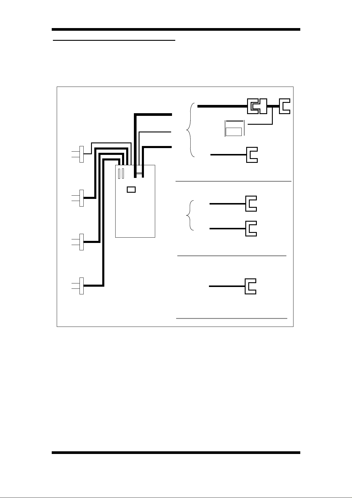
ELECTRICAL INTERFACES
The diagram below illustrates the external electrical interfaces and
options for the CashFlow
Facility For
External
Cashbox
Full Sensor
Input
Optional
Credit
Display
560.
Machine
Credit Relay
Drive
Serial
Comms
*
Machine +
Optional
Credit
RelayRelay
Optional Serial
CashFlow 560 - 4 Price
Relay
†
Comms
Power
Adaptor
Loom
Option
Connector
(remote)
CashFlow 560 - Executive
Option
Connector
(remote)
CashFlow 560 - BDV / MDB
Serial
Comms
Power and
Comms
NOTE: The machine and serial communications loom are
connected together within the changegiver for the CashFlow
560-
BDV and MDB products.
22 ©, Mars, Inc., 1996.
Page 29
CashFlow 560 changegiver Applications Design Guide
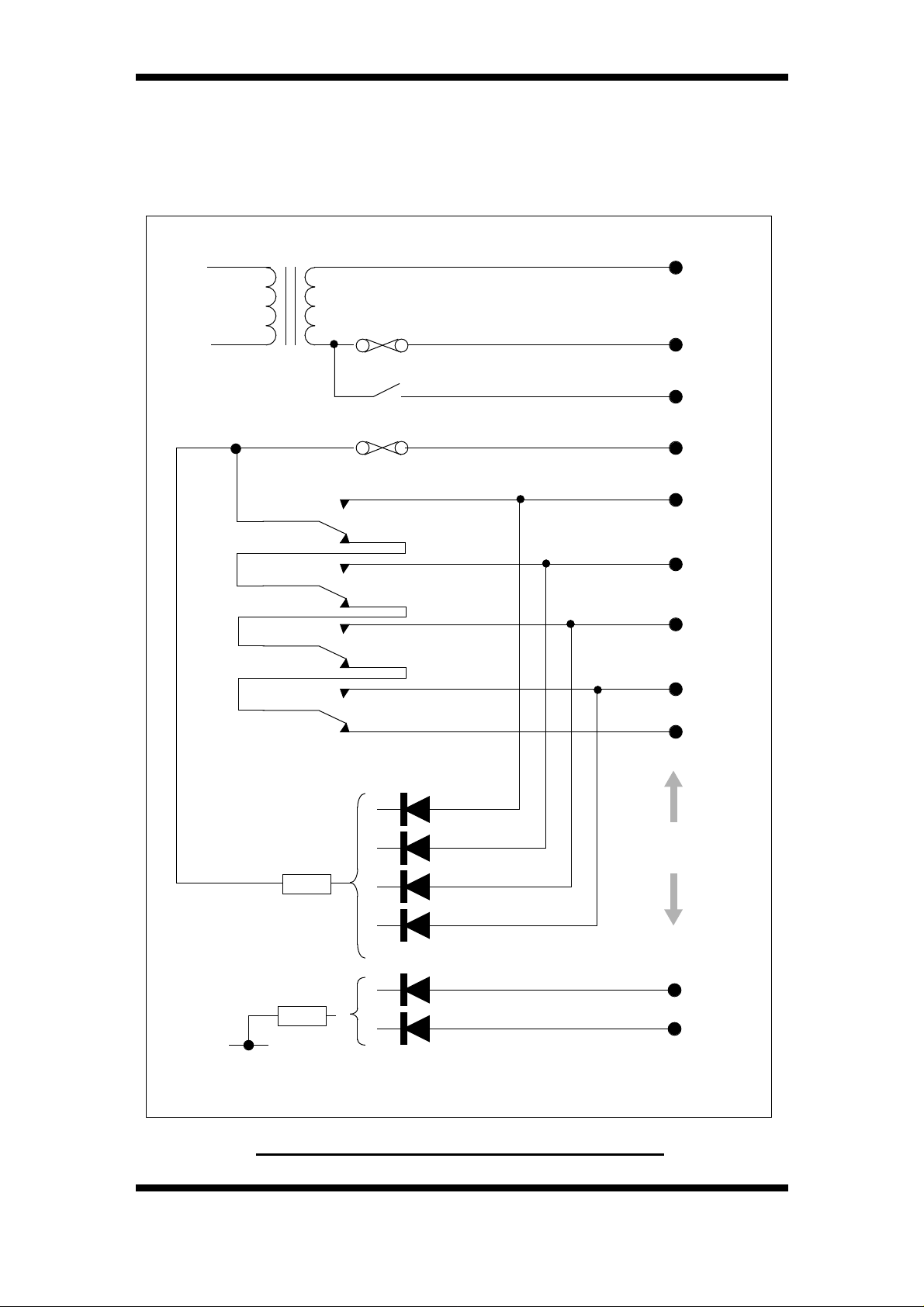
The mains electro-mechanical interface circuit diagram for
CashFlow 560 4 Price is shown below.
Line
Neutral
Exact Change
Price Line Common
Price Sense 1
Price Sense 2
Price Sense 3
Price Sense 4
Price Line 1
Price Line 2
Price Line 3
Price Line 4
Safety
Machine Interface
Connections
Escrow Accept
Neutral
Host Interface for CashFlow 560 4 Price
©, Mars, Inc., 1996. 23
Blocker
Page 30

CashFlow 560 changegiver Applications Design Guide
Protocol A Equivalent Circuit
As applicable to Executive, BDV and MDB versions.
Master
(Executive / BDV)
Vcc
0v
Vcc
100pf
TX
12
47k
RX
330
22k
Slave
(MDB)
RX
270
Serial Interface loom
Vcc
330
22k
47k
0v
TX
Vcc
270
0v
10k
Serial Interface loom
33k
0v
These circuits should be regarded as a general schematic and
not in any way representative of a particular application.
The CashFlow
560 Executive, BDV and MDB products do not
require any related electro-mechanical interfaces. However, the
Executive does require a 24V A.C. power supply as illustrated
below.
Line
Neutral
Interface for CashFlow 560 Executive
24 ©, Mars, Inc., 1996.
Page 31

CashFlow 560 changegiver Applications Design Guide
ELECTRO MECHANICAL INTERFACE
All electro-mechanical interface connections between the
changegiver and the host vending machine are electrically isolated.
Outputs are isolated via the relays (i.e. price line outputs) and the
inputs from the machine are current limited and optically isolated.
The standard electro-mechanical interface parameters for all
changegivers defined in this specification are as follows:
EXACT CHANGE OUTPUT
(Switched neutral). Rated 0.5 Amps AC resistive load. Fused 1.6
Amps thermal. Fault rating 3.5 Amps.
When the changegiver detects the change available in the tubes is
low it indicates exact change to the vending machine. The machine
normally uses this signal to illuminate a lamp informing the customer
to use the correct money.
CREDIT RELAY DRIVE
(Switched Ground). Open collector drive provided (includes flyback
diode) - 20mA @12V.
The credit relay is only available on the 4 price changegiver as an
option located outside the unit.
SAFETY LINE
(Switched Price Line Common). Rated 2.6 Amps. Fused (via price
line common) 3.15 Amps fast. Fault rating 7.0 Amps.
This output is normally connected to price line common via all the
price line relays (in their off state). When any price line becomes
active the safety line becomes open circuit within the changegiver.
PRICE LINE COMMON
(Normally connected to Line). Rated 2.6 Amps AC inductive load.
Fused 3.15 Amps fast. Fault rating 7.0 Amps.
PRICE LINE OUTPUTS
Rated 2.6 Amps AC inductive load (worst case power factor of 0.5).
Fused (via Price Line Common) 3.15 Amps fast. Fault rating 7.0
Amps.
A sense input will be seen when >1.5mA is flowing through the
sense input. When a sense input becomes active the changegiver
determines the price to be charged for the selection requested. If
sufficient credit exists it will energise the appropriate price line relay.
This relay will disconnect Safety from price line common and
connect price line common to the selected price line output enabling
the vending machine to proceed with the vend cycle.
©, Mars, Inc., 1996. 25
Page 32

CashFlow 560 changegiver Applications Design Guide
MACHINE INTERFACE
The normal idle state of the Electro-mechanical / 4 Price machine
interface with no credit is as follows:
• Blocker input active (connected to LINE)
• EA input (if present) - inactive
• Sense input lines inactive (open circuit)
• Safety Line output connected to price line common (via
ALL price line relays)
• Price line outputs inactive (open circuit)
• Credit relay off (contacts open) - when optional box
fitted
• Exact change output inactive (contacts open)
Coin Mechanism
Neutral
Live
Price Line
Common
Change
Sense
Circuit
Blocker
Sense
Circuit
Price Line Relay
Price Line Common
Neutral
Exact Change
Relay
Sense
Resistors
57k 110/240V
10k 24V
Sense
Resistors
57k 110/240V
10k 24V
Vending Machine
Live
Exact Change Lamp
Safety
Line
Price
Line
Live
NOTE: This is only representative
and not all functionality is shown.
Circuit connections are not shown
and numerous variants exist.
Selection Button
Vend Motor Relay
Vend Motor
M
Neutral
The 4 price changegiver has 4 input/output lines, providing for 4
sense inputs, and 4 price line outputs. When a product selection is
detected the appropriate price line output is enabled (if sufficient
credit exists). As the price line relay outputs are interlocked,
enabling one price line output ensures that the other price line
outputs are disabled. When the reset condition is detected the price
relay is turned off.
26 ©, Mars, Inc., 1996.
Page 33

CashFlow 560 changegiver Applications Design Guide
SINGLE / MULTI VEND
Unused credit (change) is returned to the customer either
automatically or on demand by pressing the reject lever. If the
changegiver is set to single vend mode any unused credit is
returned automatically immediately after the vend finished condition
is met. In multi vend mode the credit balance is not returned until
requested by the customer (or automatically after a selectable
timeout period has elapsed).
SENSE INPUT TIMING
During the period between pressing the product selection button
and the price line output becoming active the changegiver must
determine the price line of the selection, look-up the vend price and
decide whether to allow the vend, and if so energise the price line
relay. If the sense input from the vending machine is A.C. the sense
current is only detected during the positive half cycle, therefore it
may be 1/2 cycle (i.e. 10mS) before the sense input is detected,
leaving 25mS for everything else.
Selection Button Pressed
Sense Input active
(only during +ve cycles)
Price Line Output
1
<=
cycle
2
< 35mS
Note: Price line output becomes active only after the sense input is active and
the changegiver has authorised the vend. (i.e. credit > vend price)
Price Line Output Timing
VEND START
When a price line output has been energised the changegiver will
wait for the vend start signal. This is indicated by the blocker input
becoming inactive. If the vend start signal is not seen within 2.5 +/-
0.5 seconds of the price line output being energised the price line
©, Mars, Inc., 1996. 27
Page 34

CashFlow 560 changegiver Applications Design Guide
output is removed (excluding blocker hold reset mode). The price
line output will be energised again if the sense input is still active and
sufficient funds exist to pay for the product requested.
Price Line Output
Blocker Input
(blocker must be inactive
within 2.5 seconds for
< 2.5 seconds
Note: If blocker does not become inactive within 2.5 seconds the price line
output is turned off. It will turn on again when a valid sense input is detected.
Vend Start Timing
VEND FINISHED
valid vend start)
While the vend is in progress the vending machine holds the blocker
signal inactive. When the vend is finished the blocker signal returns
to its normal active state. As far as the changegiver is concerned the
vend is considered to have finished when the reset conditions are
met, and the price line output is disabled. The changegiver can be
programmed to several different reset conditions to suit different
vending machine interfaces:
• Blocker reset
• Delayed blocker reset
• Blocker hold reset
• Escrow accept reset
If the reset conditions are not met (i.e. the vend failed), the vend
price will be paid back to the customers credit balance.
BLOCKER RESET
The changegiver assumes the vend has finished successfully as
soon as the vend start signal is received (blocker signal is seen to
be inactive). The price line output is turned off at this point, with no
added delay. This is typically <30 mS.
28 ©, Mars, Inc., 1996.
Page 35

CashFlow 560 changegiver Applications Design Guide
DELAYED BLOCKER RESET
Blocker reset is the most commonly used reset condition
In this reset mode the price line output remains active for either 30
mS (most commonly used) or 200 +/- 10 mS after the vend start
signal is detected (blocker signal removed). The vend is assumed to
have finished successfully after this delay and the price line output
is turned off. The product may be in either 30mS or 200mS mode.
The delay is required to ensure the price line output is active for
sufficient time for some machines to latch the signal.
Selection Button Pressed
Vend in Progress
Reset Condition Met
(turn price relay off)
Vend Started
(when blocker signal removed)
The shaded area shows the state of the signal
changes sometime within this area.
Note: Price Line output removed ~30 or ~200mS
after blocker becomes inactive.
Normal Vend Cycle (Delayed Blocker Reset)
Sense Input Active
Price Line Output active
Blocker
Vend Finished
(blocker returned active)
©, Mars, Inc., 1996. 29
Page 36

CashFlow 560 changegiver Applications Design Guide
BLOCKER HOLD RESET
The changegiver waits for the vend start signal (blocker) to return
to its normal active state to indicate the vend cycle was successful.
When blocker returns the reset condition is met the price line output
is disabled.
Selection Button Pressed
Sense Input Active
Price Line Output
active
Blocker
Vend in Progress
< 30mS
Reset Condition Met
(turn price relay off)
Vend Started (when
Blocker inactive)
The shaded area shows the state of the
signal changes sometime within this area.
Note: Price Line output removed within
30mS of blocker returning active.
Normal Vend Cycle (Blocker Hold Reset)
Vend Finished (blocker
returned active)
30 ©, Mars, Inc., 1996.
Page 37

CashFlow 560 changegiver Applications Design Guide
ESCROW ACCEPT
In this mode the escrow accept (EA) input is used in conjunction with
the blocker input to indicate a successful completion of a vend cycle.
Normally, blocker removal signals the vend has started. The end of
the vend is indicated when EA becomes active while blocker is still
inactive. If the blocker signal returns to its active state before EA is
active the vend is deemed to have failed, the price output is deactivated and price of the vend is added back to the credit so that
the customer can try again or have his money back.
To allow for any fault condition the changegiver will only wait 1
minute (+/- 2 seconds) for the EA reset condition to be met. If this
does not occur the vend is assumed to have failed and is dealt with
in the same way as for blocker hold reset.
Selection Button Pressed
Sense Input Active
Price Line Output active
Escrow Accept
Blocker
Vend in Progress
Reset Condition Met
(turn price relay off)
Vend Started (when Blocker inactive)
The shaded area shows the
state of the signal changes
sometime within this area.
Normal Vend Cycle (Escrow Accept Reset)
Note: Price Line output removed
when EA becomes inactive while
blocker inactive.
Vend Finished (Blocker
returned active)
©, Mars, Inc., 1996. 31
Page 38

CashFlow 560 changegiver Applications Design Guide
PRICE SENSE / BLOCKER / ESCROW ACCEPT / VEND START/
INHIBIT INPUTS
Rated < 100 mA. Fault protection by circuit impedance.
The maximum source impedance (from vending machine) to allow
the changegiver to correctly sense an input is dependant on the
voltage profile of the unit as follows.
Mains Activated
Mains Voltage
Profile Range
20.4 - 26.4 VAC 118K ohms 10 k ohms
87 - 121 VAC 475K ohms 10 k + 47 k ohms
95 - 132 VAC 525K ohms 10 k + 47 k ohms
187 - 242 VAC 1 M ohms 10 k + 47 k ohms
212 - 264 VAC 1M1 ohms 10 k + 47 k ohms
Minimum Source
Impedance for OFF
Condition
Mains Activated
Max Load
Impedance
32 ©, Mars, Inc., 1996.
Page 39

CashFlow 560 changegiver Applications Design Guide
EXTERNAL CREDIT DISPLAY
For electro-mechanical interface applications the external display, if
fitted, can provide the following information:
• Current credit in real money (Consumer)
• Vend price in real money, used in price display
mode(Consumer)
• Accumulated credit in price teach & float modes
(Operator / Route person)
• Power-on indicator (Service engineer)
• Value of cash in tubes (Operator / Route Person)
DISPLAYING CREDIT
If there is credit in the system, either coin or value token, then the
total value of this credit will be displayed. The display will be in real
money units. Any leading zeros will be blanked. The decimal point
will be lit according to the decimal point setting in the EEPROM. A
decimal point setting of 0 indicates zero places of decimal, i.e. the
decimal point is lit on the right hand digit. A decimal point setting of
1 indicates one place of decimal, and so on. Any value of decimal
point over 4 will be ignored and no decimal point will be lit.
If there is free vend credit available, either by free vend token or host
machine free vend, the credit display will indicate this by a display
of 5 dashes on the middle segments.
If there is no credit in the system, the display will show a single 0 in
the right hand digit. No decimal point will be lit.
CANCELLING CREDIT
If you have been testing or resetting the changegiver outside of a
shifted mode you may accumulate credit in real money terms. To
cancel any credit, press the mode key once followed by the A key
twice.
©, Mars, Inc., 1996. 33
Page 40

CashFlow 560 changegiver Applications Design Guide
DISPLAYING VEND PRICE
If price display is enabled, and you make a selection whose value is
less than the current system credit, then the display will show the
price of the vend, in real money, while the selection is active.
Leading zero blanking and decimal point will be handled as the
display of credit.
DISPLAYING PRICE TEACH CREDIT
If the changegiver is in price teach mode, the current value of credit
will be displayed in real money values. Leading zero blanking and
the flashing decimal point will be handled as the display of credit.
DISPLAYING FLOAT VALUE
If the changegiver is in automatic float mode, the total value of any
coins accepted as float will be displayed in real money values.
Leading zero blanking and the flashing decimal point will be handled
as the display of credit. This value is removed when the changegiver
returns to normal operation.
POWER ON INDICATOR
On system power-up or reset, the changegiver will light all segments
of the display for 0.5 seconds. If there is no host or changegiver fault
present, the red LED will light. This will provide you with a basic
check of the display and associated H/W.
DISPLAYING TUBE VALUE
A display of the value of coins the changegiver thinks are contained
in the tubes can be obtained by pressing the mode key twice with
the tube cassette fitted. The tube contents value will be displayed for
2 seconds on the display.
Note that the calculation is based on tube counts, and on the value
of the first coin type in the tube.
34 ©, Mars, Inc., 1996.
Page 41

CashFlow 560 changegiver Applications Design Guide
VOLTAGE RANGES
The following profiled mains voltage ranges are supported across
the defined 4 price and Executive product range:
• 20.4 - 26.4VACcovering voltages 24v +10%, -15%)
• 87 - 121VAC (covering voltages 100v -13%, +21%)
• 95 - 132VAC covering voltages 120v +10%, -20.8%)
• 187 - 242 VAC covering voltages 220v +10%, -15%)
• 212 - 264 VAC covering voltages 240v +10%, -11.7%)
For details of BDV and MDB product please contact your nearest
regional Mars Electronics office.
POWER CONSUMPTION / RATING
AC Profiles BDV/MDB
Quiescent power 15VA @ 50Hz 4.5W
Maximum power 20VA @ 50Hz 8 W
Input current rating 3.52A (min) 2.2A
(min)
Internal fuse rating 1.6A (Thermal
Delay) 1.0A
TERMINAL CONNECTOR
This connector is on the front of the acceptor module. It is used with
the Mars Route Alpha 250 terminal to access and reconfigure
certain aspects of the way in which the changegiver operates. A list
of the items and relevant addresses can be found in a later section.
The connector type is: Staked pins 0.1” DIL
Pin No Function
1 Vneg (0V)
2 Data (Tx / Rx)
3 GND (0V Screen)
4 Busy
5 GND (0V Screen)
6 Vin (12V)
©, Mars, Inc., 1996. 35
Page 42

CashFlow 560 changegiver Applications Design Guide
MAN MACHINE INTERFACES
KEYPAD
All changegivers have a keypad mounted on the front face. Two
LEDs are also mounted in this area to indicate the operational state
of the changegiver. The keypad will enable the following functions
to be performed:
• Dispense coins
• Set price(s). See Note below.
• Float the changegiver
• Reset tube counts
• Home the dispensers
• Display the value of coins in the tubes
NOTE: Setting Prices is available at all times with electromechanical product, unless Route Alpha terminal address
245 has been set to inhibit.
With BDV and Executive product it will apply only when
Route Alpha 250 terminal address 238 has been activated.
Setting Prices function is not available for MDB product.
The keypad has four letter keys and a mode key. The mode key
allows shifted functions to be associated with each of the letter keys.
Two LEDs provide simple diagnostic information and will assist the
use of the keypad. The diagram below shows the layout of the
keypad and its associated labeling. The following sections describe
its operation.
Yellow LED
Red LED
MODE key
(yellow)
Keypad & Keypad Label
36 ©, Mars, Inc., 1996.
Page 43

CashFlow 560 changegiver Applications Design Guide
LED Usage
The top (yellow) LED is used to indicate whether the keypad is in
normal or shifted mode. If the LED is off, the keypad mode is in
normal mode. When the mode key is pressed, the yellow LED will
start to flash at 2 Hz (± 1%) to indicate that the shifted functions
defined by the icons on the keys, are accessible. Note that the mode
key does not need to be held down to access the shifted functions.
If no further key is pressed within 10 seconds, or the mode key is
pressed a second time, the keypad will return to its normal mode.
The yellow LED will go off, and the shifted functions will be disabled.
If a letter key is pressed within 10 seconds, then the changegiver will
turn the yellow LED on continually, and attempt to perform the
required action. See the following sections for details of the shifted
functions.
The bottom (red) LED is used to indicate the fault status of the
system. If there are no errors, the LED will be illuminated
continually. If a changegiver error is detected, then the red LED will
flash at 2Hz (± 1%). If a fault is detected on the host machine, then
the red LED will be turned off. Machine faults will take precedence
over changegiver faults.
If the state of the system requires that both LEDs flash, then they will
be synchronized to each other in anti-phase (i.e. yellow on - red off,
yellow off - red on).
Manual Coin Dispense
If the changegiver is idle (i.e. not vending or accepting coins), the
user can manually dispense coins from the 4 tubes by simply
pressing the relevant letter key. On a single press-and-release of a
letter key, the changegiver will attempt to pay a single coin from the
requested tube.
If you wish to get more than 1 coin from the tube, you can continue
to hold the key down. This will cause the changegiver to start
dispensing further coins at the rate of 1 coin every 0.5 seconds
(subject to the dispenser cycle time being less than this).
If you release the key within 3 seconds of the initial press, then
dispensing will stop after the current coin is dispensed. Multiple
dispensing is not allowed on empty tubes (tube counts = 0).
If the key is held for more than 3 seconds, dispensing will latch, and
release of the key will have no effect. The dispenser will continue to
dispense a coin every 0.3 seconds (subject to the dispenser cycle
©, Mars, Inc., 1996. 37
Page 44

CashFlow 560 changegiver Applications Design Guide
time being less than this) until the tube counts reach their
programmed safe count, or any key is pressed.
If 2, or more, letter keys are pressed at the same time, then the
changegiver will pay coins from the selected tubes in the same
manner as described above. Note that the 3 second latch time is
measured from the time the last key is pressed, and dispensing will
not unlatch until all the selected tubes reach their programmed safe
count.
Automatic Tube Float (Float Up)
You can refill the tubes to their pre-programmed float level by the
use of the float function. Float is only available if the changegiver is
idle. To access float, press the mode key to get the shifted functions,
and then press the key with the float icon (key A). Entering float
mode will clear any accumulated credit, and will be indicated on the
changegiver’s credit display by all decimal points being lit.
On entry to float, a longer time-out of 45 seconds will be started. You
can then enter coins via the acceptor. The changegiver will
automatically accept only the coins required to bring the tubes up to
their programmed float level. On a tube reaching the required float
level, any further coins of that type will be rejected. The value of any
coins accepted as float will be accumulated, and displayed on the
credit display (if fitted). This display value will be shown with the
decimal point flashing.
During float the yellow LED will remain on, indicating that a shifted
function is active. The changegiver will exit float mode, and turn off
the yellow LED, if any of the following occur:
• No float coins accepted during a 45 second period
• The float key (A) is pressed
• The float down (C) key is pressed
• The reset tube counts key is pressed
Note that on exit of float, there is no need to press the mode key first,
as the shifted functions are already active. When float mode is
exited the changegiver will clear down the credit display, and
resume normal coin acceptance.
If float mode is exited by either of the first two methods above, then
the tube counts will not be modified further. If float mode is exit by
pressing the reset tube counts key, then the tube counts will all be
set to their pre-programmed float levels.
38 ©, Mars, Inc., 1996.
Page 45

CashFlow 560 changegiver Applications Design Guide
Float Down Mode
When you wish to float down the tubes, simply press the mode key
to get to the shifted functions, then press the A key to enter float
mode, followed by the C key. At this point the changegiver will start
to dispense coins until all tube counts reach the pre-programmed
float levels. Note that if all counts were equal to or less than the float
levels, then no dispense will occur.
Resetting Tube Counts
You can force the tube counts to be set to their pre-programmed
values by use of the reset tube counts function. In order to avoid
inadvertent resetting of tube counts, this function is only enabled if
the changegiver is in float mode, and an IDTS audit FEM is not
present.
If key B is pressed while the changegiver is in float mode, then all of
the tube counts for the 4 main tubes will be set to their preprogrammed float levels. The changegiver will then exit float mode.
If the actual number of coins in the tubes do not match these float
levels, then the coin counts will be incorrect until recalibration
occurs. If access to this function is attempted when the changegiver
is not in float mode, i.e. pressing the mode key, then pressing the
reset key, it will be ignored. The keypad will revert back to normal
mode after 10 seconds and the yellow LED will then stop flashing.
Price Teach
Subject to the earlier note the prices held by the changegiver can be
set using the price teach function. Price teach is only available if the
changegiver is idle. To access price teach, press the mode key to
get the shifted functions, then press the key with the price icon (key
C). Entering price teach mode will clear any accumulated credit, and
allow the user to clear credit, and will be indicated on the
changegiver’s credit display by all decimal points being lit.
On entry to price teach, a longer time-out of 45 seconds will
commence. You can then enter coins via the acceptor to the value
required for the price to be set. Any coins entered will be
accumulated as credit, and displayed on the credit display, if fitted.
This display value will be shown with the decimal point flashing.
If there is accumulated credit, then any selection which becomes
active will have its price set to the value of credit accumulated. If no
credit was accumulated, then any selections made will not have
their price modified. This is to prevent inadvertent zeroing of prices
on permanent sense machines. Price teach only allows the setting
of non-zero prices. Should you wish to clear a price to zero, then the
Route Alpha 250 terminal must be used.
©, Mars, Inc., 1996. 39
Page 46

CashFlow 560 changegiver Applications Design Guide
The sequence of inserting coins then making a selection can be
repeated for all selections for which you wish to modify the price.
Note that the main principle of price teach is that selections will have
their price set to the current accumulated credit value, so that if a
number of selections are required to be set to the same price, once
the correct credit value is reached, all that needs to be done is to
press the selection buttons.
During price teach the yellow LED will remain on, indicating that a
shifted function is active. In addition, all keys except the price teach
key will be ignored. The changegiver will exit price teach mode, and
turn off the LED, if any of the following occur:
• No activity relating to price teach made during a 45
second period.
• The price teach key is pressed.
Note that on exiting price teach, there is no need to press the mode
key first, as the shifted functions are already active. When price
teach mode is exited the changegiver will attempt to return any
accumulated credit to the user using the tube coins.
Note that on serial interface changegivers, the prices are not
normally held in the changegiver and are thus inaccessible to this
form of update, unless the price holding option is enabled via the
support terminal.
Homing the Dispensers
You can home all the dispenser arms by first pressing the mode key
to get the shifted functions, then pressing the mode key a second
time. This will home each of the dispenser arms which are not seen
to be at home, as read by the position sensors. This will only work if
the tube cassette is removed.
Displaying Tube Value
You can easily get a display of the value of coins the changegiver
thinks are contained in the tubes by pressing the mode key twice
with the tube cassette fitted. This will cause the tube contents value
to be displayed for 2 seconds on the changegiver’s credit display.
Note that only tubes which are set up as fitted will be included in this
calculation. Note also the calculation is based on tube counts and
on the value of the first coin type in the tube.
40 ©, Mars, Inc., 1996.
Page 47

CashFlow 560 changegiver Applications Design Guide
INTERNAL DIAGNOSTICS & ERROR HANDLING
The indication of an error being present either in the host or in the
changegiver is given by the red LED. This section details various
errors, and the action taken by the changegiver.
• Host machine problems
• Coin handling problems
• On-board EEPROM problems
• Audit FEM problems
• FIB communication errors
• Miscellaneous errors
HOST MACHINE PROBLEMS
Host Inhibited
On both electro-mechanical and electronic hosts, an indication is
provided to the changegiver if the host is inhibited (e.g. blocker
inactive on electro-mechanical machines, no polling on MDB). The
error handling for this condition is:
• Indicate host error on LED
• Disable all coin acceptance in normal mode
• Disable all coin acceptance in float mode
• Disable all coin acceptance in price teach mode
• Manual dispense is still allowed
• Route Alpha 250 terminal comms still allowed
• Changegiver will continually check if host is re-enabled
Removal of Blocker
The start of vend condition on electro-mechanical hosts is signalled
by blocker becoming inactive after the price relay has been turned
on. Normally there is a 2.5 second timeout on this, which will
terminate the vend sequence with no loss of credit should blocker
not go inactive. In blocker hold mode, due to the possibility of
frauding certain machines, this timeout is not used. Therefore, if the
start of the vend (as signalled by the removal of the blocker signal)
does not occur, the following error state will result:
• Indicate host error on LED
• Inhibit all changegiver functions
• Changegiver will continually check if vend starts
©, Mars, Inc., 1996. 41
Page 48

CashFlow 560 changegiver Applications Design Guide
Blocker Return
The end of vend condition on electro-mechanical hosts depends on
the reset mode selected. In blocker hold mode, the end of vend is
signalled by the return of the blocker signal. If this does not occur,
the following error state will result:
• Indicate host error on LED
• Inhibit all changegiver functions
• Changegiver will continually check if host is re-enabled
Cashbox Full
An input is provided for a cashbox full sensor (provided by the host).
The error handling for this sensor is:
• Indicate host error on LED
• Set cashbox full error flag (code 7 in error register)
• Disable all coin acceptance in normal mode
• Disable all coin acceptance in float mode
• Disable all coin acceptance in price teach mode
• Manual dispense is still allowed
• Terminal comms is still allowed
• Cashbox must be emptied to reset error
Bad Replies Received
Protocol A serial communications error handling is summarised
below:
• Indicate host error on LED
• Suspend operation for 100mS
• Abort sequence and revert to sending status
• Disable all coin acceptance in normal mode
• Manual dispense is still allowed
• Allow return of credit
• Terminal comms is still allowed
• Changegiver will continually check if failure rectified
42 ©, Mars, Inc., 1996.
Page 49

CashFlow 560 changegiver Applications Design Guide
No Response
• Indicate host error on LED
COIN HANDLING PROBLEMS
Full Sensor Failure
• Disable all coin acceptance in normal mode
• Manual dispense is still allowed
• Allow return of credit
• Terminal comms is still allowed
• Changegiver will continually check if failure rectified
• Indicate changegiver error on LED
• Disable routing to affected tube
• Set required code in full sensor error register
• Dispense from tube is still allowed
• On coin acceptance or dispense, changegiver will
check if failure rectified
Post Gate Strobe (PGS) Failure
• Indicate changegiver error on LED
• Set PGS error flag (code 7 in full sensor error register)
• On coin acceptance or rejection, changegiver will
check if failure rectified
Tube Cassette Removal
• Indicate changegiver error on LED
• Disable routing to tubes (all coins to cashbox)
• Set cassette removed error flag (code 4 in operational
error register)
• Dispense is still allowed
• Signal exact change
• On coin acceptance or dispense, changegiver will
check if failure rectified
©, Mars, Inc., 1996. 43
Page 50

CashFlow 560 changegiver Applications Design Guide
Home Sensor Failure
• Indicate changegiver error on LED
Motor Failure / Jam
• Disable use of affected tube
• Set required bit(s) in disabled tubes error register
• Signal exact change
• Manual dispense attempts from the tube are still
allowed
• Error can be cleared by removing the source of the
error and performing a manual dispense, or by using
the Mars
• Indicate changegiver error on LED
• Disable use of affected tube(s)
®
Route Alpha 250 terminal.
• Set required codes in disabled tubes error register
• Signal exact change
• Manual dispense attempts from the tube are still
allowed
• Error can be cleared by removing the source of the
error and performing a manual dispense, or by using
the Mars
ON-BOARD EEPROM PROBLEMS
Incorrect Configuration vsn. No.
If the configuration file version number in the on-board EEPROM
does not match the version expected in the software, the following
error handling applies:
• Set code 4 of EEPROM error register
• Indicate changegiver error on LED
®
Route Alpha 250 terminal.
• No upload of EEPROM data will occur
• All coin acceptance will be disabled
• The keypad will be disabled, apart from the mode key
• Terminal comms. still allowed
• No save of data to EEPROM on power fail
44 ©, Mars, Inc., 1996.
Page 51

CashFlow 560 changegiver Applications Design Guide
• The configuration version number must be corrected.
The error will then be cleared on changegiver re-
EEPROM Corruption
If a corruption is detected in the EEPROM at upload time, the
following error handling applies:
• Set code 0 - 1 of EEPROM error register
• Indicate changegiver error on LED
• No upload of EEPROM data will occur
• All coin acceptance will be disabled
• The keypad will be disabled, apart from the mode key
initialisation. This can be done by;
• Clearing the error flag,
• Updating the EEPROM version number,
• Re-initialising.
• Terminal comms is still allowed
• No save of data to EEPROM on power fail
While a reset device error appears to clear the error, note that there
will be no configuration data uploaded into RAM, and hence the
changegiver’s operation will be indeterminate. After clearing the
error, the checksum of the affected page should be corrected and
the changegiver re-initialised.
Write Timeout
If a timeout occurs when writing to theEEPROM, the following error
handling applies:
• Set bit 7 of EEPROM error register
• Indicate changegiver error on LED
• All coin acceptance will be disabled
• The keypad will remain enabled, with manual dispense
still allowed
• Terminal comms is still allowed
• No save of data to EEPROM on power fail
• Changegiver must be switched off to reset error.
©, Mars, Inc., 1996. 45
Page 52

CashFlow 560 changegiver Applications Design Guide
AUDIT FEM PROBLEMS
Audit not initialised
If a FEM is present but has not be initialised, the following applies:
• Set code 5 in error register
• Indicate changegiver error on LED
• No coin in / out events will be audited
• Vending is disabled
• Audit must be initialised to clear error.
Audit FEM corrupt
If a FEM is present but is corrupt, the following applies:
• Set code 2 in error register
• Indicate changegiver error on LED
• Suspend all changegiver operation apart from FIB
comms
• Mode key still operates
• Corruption may self repair if power is cycled. If not,
then FEM must be replaced.
Audit removed
If a FEM had been present but is now removed, the following
applies:
• Set code 3 in register
• Indicate changegiver error on LED
• Suspend all changegiver operation apart from FIB
comms
• Mode key still operates
Audit must be re-fitted and changegiver re-initialised to clear error.
HOST INTELLIGENT INTERFACE(HI
The HI
between the acceptor and the control board
HI2 Error
If an error occurs in the HI
handling applies:
46 ©, Mars, Inc., 1996.
2
is the internal comms highway that handles all messages
2
protocol stack the following error
• Indicate changegiver error on LED
2
) ERRORS
Page 53

CashFlow 560 changegiver Applications Design Guide
• Set codes 2 / 3 in error register
• Will not allow the changegiver to enter float or teach
• Coin acceptance inhibited
• Manual dispense is not allowed
• Terminal comms is still allowed (if access is permitted)
• Changegiver will continually check if failure rectified
MISCELLANEOUS ERRORS
Acceptor Initialising Error
If there is a failure to transfer over data between the acceptor and
control board on power-up, the following error handling applies:
• Indicate changegiver error on LED
modes.
• Set code 1 in error register
• All coin acceptance will be disabled
• Manual dispense is still allowed
• Terminal comms is still allowed
While a reset device error appears to clear the error, note that the
data for coin routing, inhibits, coin types, etc. may not have been
correctly passed between the acceptor and the changegiver, and
hence the changegiver’s operation will be indeterminate. After
clearing the cause of the error the changegiver should be reinitialised.
©, Mars, Inc., 1996. 47
Page 54

CashFlow 560 changegiver Applications Design Guide
VIA MARS ROUTE ALPHA 250 TERMINAL
With a Mars Route Alpha 250 terminal you can re-configure any of
the functions available for a particular product. The terminal is
connected to the acceptor via a six way connector which plugs into
the front of the acceptor.
The terminal is used to check or change certain data which affects
the way the changegiver operates. The data is held in addresses.
Each address has a unique number which identifies the feature you
wish to read or change e.g. if you want to change from single vend
to multi vend then you need to go to address number 226 and put in
a 1 (single vend is a 0).
The following pages will explain how to access and change the data
in certain addresses. At the end of this section there is a list of
addresses and the relevant values. Particular reference should be
made to the symbols in this section which indicate the applications
(i.e. electromechanical, Executive, BDV and MDB) for which each
address is appropriate.
48 ©, Mars, Inc., 1996.
Page 55

CashFlow 560 changegiver Applications Design Guide
KEY FUNCTIONS
ENTER
LEFT
Reset Key: used to reset all modes and to initialise any settings that
you have changed. If the reset key is pressed while an address is
being updated then the address may not be updated. The reset key
must be pressed to store the changes that you have made.
Up Key: used to increase the value displayed on the screen.
Down Key: used to decrease the value displayed on the screen.
Left Key: used to scroll the display to the left when a large number
is being accessed that cannot be fully displayed on the screen.
RESET
DISPLAY
UP
RIGHT
DOWN
Right Key: used to scroll the display to the right when a large
number is being accessed that cannot be fully displayed on the
screen.
Enter Key: used to change between the address and data displays.
Other Facilities of the Terminal
The terminal has several features to speed up its use. This includes
the ability to scan at a higher speed with the keys auto repeating, to
automatically roll over from its highest to lowest address and to
inform the operator should a communication error occur.
Should you need to know which version numbers of the software is
used in the changegiver the UP key is pressed while the terminal is
2
in reset mode. The terminal will firstly display the acceptor HI
address, if the UP key is pressed again the acceptor software
version number will be displayed. Pressing the UP key again will
display the acceptor eeprom number and if pressed again the
acceptor configuration code. Pressing the RIGHT key will display
the changegiver’s software number
To return to normal operation press the RESET key.
node
©, Mars, Inc., 1996. 49
Page 56

CashFlow 560 changegiver Applications Design Guide
Auto Repeating Keys
If either the UP or DOWN keys are kept pressed they automatically
repeat. The repeat speed of the key increases the longer the key is
held down.
Double Click Hotkeying
If a key is doubled clicked (pressed twice in quick succession) then
this causes the address number to increment by a larger amount.
e.g. if the user starts at address number 1 then double clicks the UP
key, the address will jump to 40, double click again the address will
jump to address 100 etc. This is useful as the addresses used for
the changegiver start at address 200. You can also double click the
DOWN key to decrement by larger amounts.
USING THE TERMINAL
As soon as the terminal is connected to a changegiver it powers up
and interrogates the product.
The terminal display will clear and briefly show a message that
indicates the version of software in the terminal. A display of [0 1.0]
means software with a version number of 1.0 is fitted in the terminal.
Power up message Software version = 1.0
After a few seconds the display will show the number [1.] or [1.-]. Not
all configuration items are applicable to every product but all the
address values are shown on the display. If the value for the
address is applicable to the product a dash will be present at the far
right position on the display. The value can then be accessed and
changed if required.
No dash displayed
Address is not accessible
for this product
Dash is displayed Address
is therefore accessible
50 ©, Mars, Inc., 1996.
Page 57

CashFlow 560 changegiver Applications Design Guide
The basic operation to alter the information held in an address is:
1 Connect the terminal to the CashFlow
product.
2 Wait for the terminal to power up correctly.
3 Select the address by using the UP and DOWN keys.
4 Examine the data by pressing the ENTER key.
5 Alter the data value by pressing the UP or DOWN keys
until the new value has been reached.
6 Press the ENTER key to return to displaying addresses.
7 Press the RESET key to initialise the new value.
When the terminal is displaying values stored at addresses, no
decimal point will be displayed.
If an error occurs with the communication between the terminal and
the changegiver the display will show an error message of four half
height zeroes.
Error message
This message will stay on the display. Pressing the RESET key may
clear the fault. The display will then revert to showing the current
address. If the error occurred while updating an address then the
value of that address should be checked as it may not have been
updated correctly. If, after pressing the RESET key, the fault
remains the error message will stay and you need to return the
terminal for repair.
As the screen is capable of only displaying four digits at any one
time the number displayed on the screen can be scrolled if it is
greater than 9999 by using the LEFT and RIGHT keys. The left or
rightmost digit will flash indicating an extra digit can be examined by
use of the scrolling keys e.g. Value is 12345
press RIGHT key
flashing
press LEFT key
©, Mars, Inc., 1996. 51
flashing
Page 58

CashFlow 560 changegiver Applications Design Guide
VISUAL AUDIT
033330564
157847001 R1
Function Expansion Module
Visual Audit can be obtained, from the electro-mechanical and
Executive products only, when an audit function expansion module
(FEM) is installed as an accessory on to the Control PCB.
Data can be viewed with the use of a Route Alpha 250 terminal and
the process for using this method follows below. Data is also
®
available via a Mars
through an interface loom from the changegiver, through a DEX/
UCS jack-plug connected to a Mars
red optical interrogation point in the side of the machine, also using
the MEQ terminal.
hand-held printer which can be accessed
®
MEQ terminal, or from an infra-
®
Mars
Visual Audit Interrogation
The Route Alpha 250 terminal display may not be able to show all
details for each address. In order to ensure that all data has been
read two quite separate addresses must be interrogated, one
consisting of the least significant (ls) digits, and the other the most
significant (ms) digits of the data.
To convert these two readings to a single audit value the (ms) value
shown must be multiplied by 65536 and the (ls) figure added to the
result.
52 ©, Mars, Inc., 1996.
Hand-Held Printer
Mars® MEQ Terminal
Page 59

CashFlow 560 changegiver Applications Design Guide
The following process should be followed to use the Route Alpha
250 terminal for retrieval of data:
• Firstly select the required address using the Up and
DOWN keys.
• Press ENTER to display the contents of the address. If
the value exceeds four digits the LEFT and RIGHT
keys are used to scroll the display left or right.
EXAMPLE. (To read the Cash In Tubes value)
• Select address 900
• Press ENTER to display the (ls) value, (e.g 54919)
• Press ENTER to return to address mode
• Press UP to select address 901
• Press ENTER to display the (ms) value, (e.g. 18)
• Multiply (ms) value by 65536 (18 x 65536 = 1179648)
and add (ls) value. (1179648 + 54919 = 1234567)
NOTES
All values are displayed on the terminal with no decimal point.
In order to reset the interim values address 999 must be used,
ensuring that it is set to 9.
All values displayed will be in the range of 0 - 65535.
The relevant addresses for the Route Aplha 250 terminal in the
following list are 900-999.
©, Mars, Inc., 1996. 53
Page 60

CashFlow 560 changegiver Applications Design Guide
Route Alpha 250 Address Applications
The symbols below appear on the following pages together with
most of the following Route Alpha 250 address numbers. They can
be used as an aid to indicate which variety of product that each
address is used with.
Where no symbol is used this address applies to 4 price electromechanical products only.
✖ = Address used with 4 price and Executive only
✙ = Address used with 4 price, Executive and BDV only
▲ = Address used with 4 price, Executive, BDV and MDB
■ = Address used with 4 price and BDV only
✔ = Address used with Executive and BDV only
✸ = Address used with BDV only
◆ = Address used with MDB only
54 ©, Mars, Inc., 1996.
Page 61

CashFlow 560 changegiver Applications Design Guide
Addresses and Values
The table below shows you the address of each item that can be reconfigured and their possible values.
Address
✙
21 - 32
✙
200
✙
201-204
Parameter
Coin types 1 - 12 0-2
Maximum credit 0-65,535
Prices 1 - 4 0-65,535 value of prices 1 - 4
Range
0 = coin
1 = value token
2 = vend token
maximum credit 4 price,
maximum change BDV
Meaning
✖
205-225
✙
226
✙
227
228
Prices 5 - 25
(When audit FEM
fitted only)
Single/Multivend 0 -1
Escrow return inhibit 0 -1
Reset mode
(Electromech only)
0-65,535 value of prices 5 - 25
0 - 4
0 = single vend
1 = multivend
0 = escrow allowed
1 = escrow inhibited
0 = blocker reset
1 = delayed blocker reset
(30ms)
2 = delayed blocker reset
(200ms)
3 = blocker hold reset
4 = after escrow accept
signal
▲
229
▲
230
Coin inhibit, coins 1-4
for multiple coin
inhibit,add together
e.g. 1 + 8 = 9 so coins
1 & 4 are inhibited
Coin inhibit, coins 5-8 0 -15
©, Mars, Inc., 1996. 55
0 -15
0 = no coins inhibited
1 = inhibit coin 1
2 = inhibit coin 2
4 = inhibit coin 3
8 = inhibit coin 4
0 = no coins inhibited
1 = inhibit coin 5
2 = inhibit coin 6
4 = inhibit coin 7
8 = inhibit coin 8
Page 62

CashFlow 560 changegiver Applications Design Guide
0 -15
Range
0 = no coins inhibited
1 = inhibit coin 9
2 = inhibit coin 10
4 = inhibit coin 11
8 = inhibit coin 12
Meaning
Address
▲
231
Parameter
Coin inhibit,
coins 9 -12
✙
232
✙
233
✙
234
✙
235
✙
236
✙
237
Exact change inhibit
group
Inhibit coins 1 - 4
Exact change inhibit
group
Inhibit coins 5 - 8
Exact change inhibit
group
Inhibit coins 9 - 12
Change delay 0 - 255
Exact change
equation
part1
Exact change
equation
part 2
0 -15
0 -15
0 -15
0 - 15 1/2/4/8 = tubes A/B/C/D
0 - 15 1/2/4/8 = tubes A/B/C/D
1 = coin 1
2 = coin 2
4 = coin 3
8 = coin 4
1 = coin 5
2 = coin 6
4 = coin 7
8 = coin 8
1 = coin 9
2 = coin 10
4 = coin 11
8 = coin 12
delay in 1 second steps
255 = infinite delay
✔
238
✙
239
✔
240
▲
241
✙
242
56 ©, Mars, Inc., 1996.
Price hold 0 - 1
Price display options 0 -1
Coin scaling factor 0 - 250
Decimal point position 0 - 3 decimal point position
Overpay inhibit
options
0 -1
0 = do not hold price
1 = hold price
0 = do not display price
1 = display price
0 = overpay allowed
1 = overpay Inhibited
Page 63

CashFlow 560 changegiver Applications Design Guide
Address
Parameter
Range
Meaning
✙
243
✙
244
✙
245
246
▲
247
▲
251-254
▲
261-264
▲
271-274
▲
281-284
Clear overpay inhibit
options
Keypad inhibit options 0 -1
Price teach inhibit
options
Fast sense options
(Electromech only)
Auto tube inventory
options (float down)
Tubes A - D
float level options
Tubes A - D
full count options
Tubes A - D
low count options
Tubes A - D
safe count options
0 -1
0 -1
0 -1
0 -1
0 - 255
0 - 255
0 - 255
0 - 7
0 = cleardown allowed
1 = cleardown Inhibited
0 = keypad enabled
1 = keypad inhibited
0 = price teach allowed
1 = price teach inhibited
0 = normal
1 = fast sense
0 = float down disabled
1 = float down enabled
number of coins in a tube to
be floated to
number of coins in a tube
that activate the full sensor
number of coins in a tube
that activate the low sensor
minimum number of coins
that must be left in a tube
(this number is multiplied by
2 in the changegiver)
▲
291-294
▲
301-304
▲
310
▲
311-314
▲
321-332
1st coin type in tubes
A -D
(ref. addresses 21-32)
2nd coin type in tubes
A - D
(ref. addresses 21-32)
Value of coins in
tubes READ ONLY
Tubes A - D current
coin count
READ ONLY
value of coins 1 - 12 0-65,535
©, Mars, Inc., 1996. 57
0 - 12
0 - 12 coin number, 0 = no coin
0-65,535 value of coins in all tubes
0 - 255
coin number 0 = no coin
(taken from coinset label
reading from left to right and
top to bottom)
current number of coins in
tube
Page 64

CashFlow 560 changegiver Applications Design Guide
Address
Parameter
Range
Meaning
▲
340
▲
341
▲
342
▲
343
▲
344
Full sensor errors
READ ONLY
Tube dis-abled data 0 - 31
EEPROM errors (i)
data
READ ONLY
EEPROM errors (ii)
data
READ ONLY
Operational errors (i)
data
READ ONLY
0 - 255
0 - 15
0 - 15
0 - 15
tubes 1/2/4/8 = A/B/C/D
128 = Post gate strobe
errors
tubes A/B/C/D
READ ONLY
1 = errors in page 0
2 = errors in page 1
4 = corrupt audit FEM
8 = audit FEM removed
1 = incorrect configuration
version
2 = audit FEM present but
not initialised
4= undefined
8 = internal write error
1 = coinset code error
2 = acceptor error
4 = HII hardware error
8 = HII transmit error
▲
345
✸
346
✸
347
▲
349
✖
360
✖
361
Operational errors (ii)
data
READ ONLY
BDV errors (i) options
BDV errors (ii) options 0 -15
Reset error flags
options
Audit module - VMC
identification code
Audit module printout language
options
0 - 15
0 - 15
0 - 1
0-65,535 vending machine ID
0 - 4
1= coin cassette removed
2=protocol A receive error
4=protocol A transmit error
8 = cashbox full error
1 = audit timed out
2 = vmc timed out
4 = cpc timed out
1 = audit incompatible
2 = vmc incompatible
4 = cpc incompatible
0 = do not reset
1 = reset error flags
0 = English
1 = French
2 = German
3 = Dutch
4 = Spanish
58 ©, Mars, Inc., 1996.
Page 65

CashFlow 560 changegiver Applications Design Guide
0 - 2
Range
0 = basic
1 = basic + interim vend
report
2 = basic + interim vend +
free vend report
Meaning
Address
✖
362
Parameter
Audit module printout type options
✖
363
✖
364
✖
365
Audit module printout product limit
Audit module installation day
Audit module installation month
0 - 25
1 - 31
1 - 12
limit details on printout to
first few specified price lines
day of installation into the
machine
month of installation into the
machine
✖
366
✸
380
✸
381
✸
382
✸
383
Audit module installation year
Discount award
options
Discount trigger
options
Link Master ID 0 - 9999 ID code of link master node
Exact change offset
(Used in conjunction
with addresses
271-274)
0 - 99
0 - 9999
0 - 9999
0 - 15
year of installation into the
machine
amount added to credit
when the vended value
exceeds the discount trigger
if vended value exceeds this
value then the award will be
added to the system credit
additional setting allows a
more advanced warning to
be given of the exact
change requirement
✸
384
✸
385
✸
386
✸
387
Max coin credit 0-65,535
Audit unit is BDV 0 - 1
VMC unit BDV 0 - 1
Cashless payment
controller (CPC) unit
is BDV
©, Mars, Inc., 1996. 59
0 - 1
maximum coin credit that
can be accepted by the
changegiver
0 = audit unit is not BDV,
1 = audit unit is BDV
0 = VMC is not BDV,
1 = VMC is BDV
0 = CPC is not BDV,
1 = CPC is BDV
Page 66

CashFlow 560 changegiver Applications Design Guide
Address
Parameter
Range
Meaning
✸
388
✸
389
✸
390
✸
391
✸
392
✸
393
◆
421-432
✙
600
Card revaluation
allowed
Audit unit fitted 0 - 1
VMC unit fitted 0 - 1 0 = not fitted, 1 = VMC fitted
CPC unit fitted 0 - 1 0 = not fitted, 1 = CPC fitted
BDV exact change
equation
Audit initialisation
required
MDB changegiver
coin types 1 - 12
Number of bills 0 -15
0 - 1
0 - 1
0 - 1
0 - 2
0 = revaluation not allowed,
1 = revaluation allowed
0 = not fitted,
1 = audit unit fitted
0 = normal, 1 = use BDV
exact change equation
0 = initialisation not required
1 = initialisation required
0 = coin
1 = token
2 = token
number of bill supported bt
BVI
✙
601
✙
602
✙
603
✙
611
✙
612
✙
613
Value of bill 1 0-65535
Value of bill 2 0-65535
Value of bill 3 0-65535
Bill scaling factor 0-65535
Bill default inhibit map 0 -7
Bill exact change
inhibit map
0 -7
bill value 1 in real currency
units. Bill values should be
in equal/ascending order
bill value 2 in real currency
units. Bill values should be
in equal/ascending order
bill value 3 in real currency
units. Bill values should be
in equal/ascending order
multiplier required to
convert number of credit
pulses received by the BVI
to real currency units
value = sum of codes where
1/2/4 = lowest / middle /
highest bill inhibit
value = sum of codes where
1/2/4 = lowest / middle /
highest bill inhibit
60 ©, Mars, Inc., 1996.
Page 67

CashFlow 560 changegiver Applications Design Guide
Address
Parameter
Range
Meaning
✖
900
✖
901
✖
902
✖
903
✖
904
✖
905
✖
906
✖
907
✖
908
Cash in tubes (ls) 0-65535 visual audit
Cash in tubes (ms) 0-65535 visual audit
Value of cash sales
interim (ls)
Value of cash sales
interim (ms)
Number of cash sales
interim (ls)
Number of cash sales
interim (ms)
Value of cash in (ls) 0-65535 visual audit
Value of cash in (ms) 0-65535 visual audit
Cash to cash-box (ls) 0-65535 visual audit
0-65535 visual audit
0-65535 visual audit
0-65535 visual audit
0-65535 visual audit
✖
909
✖
910
✖
911
✖
912
✖
913
✖
914
✖
915
✖
916
Cash to cash-box
(ms)
Cash to tubes (ls) 0-65535 visual audit
Cash to tubes (ms) 0-65535 visual audit
Dispensed cash (ls) 0-65535 visual audit
Dispensed cash (ms) 0-65535 visual audit
Manually invented
cash (ls
Manually invented
cash (ms)
Overpay (ls) 0-65535 visual audit
0-65535 visual audit
0-65535 visual audit
0-65535 visual audit
©, Mars, Inc., 1996. 61
Page 68

CashFlow 560 changegiver Applications Design Guide
Address
Parameter
Range
Meaning
✖
917
✖
918
✖
919
✖
920
✖
921
✖
922
✖
923
✖
924
✖
925
Overpay (ms) 0-65535 visual audit
Exact change vend
value (ls)
Exact change vend
value (ms)
Value of cash
manually filled (ls)
Value of cash
manually filled (ms)
Value of free sales
interim (ls)
Value of free sales
interim (ms)
Number of free sales
interim (ls)
Number of free sales
interim (ms)
0-65535 visual audit
0-65535 visual audit
0-65535 visual audit
0-65535 visual audit
0-65535 visual audit
0-65535 visual audit
0-65535 visual audit
0-65535 visual audit
✖
926
✖
927
✖
928
✖
929
✖
930
✖
931
✖
932
✖
933
Printout number (ls) 0-65535 visual audit
Printout number (ms) 0-65535 visual audit
Last printout number
(ls
Last printout number
(ms)
Value of cash sales
total (ls)
Value of cash sales
total (ms)
Number of cash sales
total (ls)
Number of cash sales
total (ms)
0-65535 visual audit
0-65535 visual audit
0-65535 visual audit
0-65535 visual audit
0-65535 visual audit
0-65535 visual audit
62 ©, Mars, Inc., 1996.
Page 69

CashFlow 560 changegiver Applications Design Guide
Address
Parameter
Range
Meaning
✖
934
✖
935
✖
936
✖
937
✖
938
✖
939
✖
940
✖
941
✖
942
Value of free sales
total (ls)
Value of free sales
total (ms)
Number of free sales
total (ls)
Number of free sales
total (ms)
Value of bills in total
(ls)
Value of bills in total
(ms)
Interim value of bills
(ls)
Interim value of bills
(ms)
Value of vend token
sales (ls)
0-65535 visual audit
0-65535 visual audit
0-65535 visual audit
0-65535 visual audit
0-65535
0-65535
0-65535
0-65535
0-65535 visual audit
visual audit (when used with
Bill Validator Interface)
visual audit (when used with
Bill Validator Interface)
visual audit (when used with
Bill Validator Interface)
visual audit (when used with
Bill Validator Interface)
✖
943
Value of vend token
sales (ms)
0-65535 visual audit
✖
946-966
(Evens
only)
Interim of products
0-10 (ls)
0-65535 visual audit
✖
947-967
(Odds
only)
999 Interim reset address 0-65535
Interim of products
0-10 (ms)
0-65535 visual audit
must be set to 9 to cause
interims to be reset
©, Mars, Inc., 1996. 63
Page 70

CashFlow 560 changegiver Applications Design Guide
DIAGNOSING TERMINAL PROBLEMS
Terminal displays an
error message at
power up
Terminal displays an
error message when
changing from
address to data
mode or vice versa
Terminal powers up
correctly but no
addresses are
accessible
SYMPTON CAUSE SOLUTION
Communications error Press RESET
Communications error
between terminal and
product or the terminal
does not recognise the
product it has been
connected to
The product is not
compatible with the
terminal
Repeat last
operation
Requires a
different
terminal/
software
Terminal does not
power up
Terminal powers up
but one of the keys
does not work
Non standard
characters printed on
display
Bad connections or
Faulty cable
Faulty key Use the self
Faulty Route Alpha 250
terminal
Check
connections at
either end of
lead. Replace
lead
test feature.
If the key is
faulty send unit
for repair
Send unit for
repair
64 ©, Mars, Inc., 1996.
Page 71

CashFlow 560 changegiver Applications Design Guide
Testing the Terminal
It is possible to test all the features of the terminal itself by putting
the unit into a special test mode. To enter the test mode hold the
ENTER key pressed when powering the unit up. The display will
initially show three digits indicating the result of an automatic on
board test. The display format is:
[<BUSY state> <DATA state> <AUTO TEST result>] where
<BUSY state> = current state of BUSY line, 0 = low, 1 = high
<DATA state> = current state of DATA line, 0 =low, 1=high
<AUTO TEST result> = result of automatic test
0 = Pass
1 = BUSY line error
Pressing the ENTER key activates the next stage of test.
The LCD is tested by displaying a pattern of four identical digits on
the display. The digits alter every 1/2 second and the display should
be examined to check all the digits are formed correctly.
Display will show:
[0000], [1111], [2222], [3333], [4444], [5555], [6666], [7777], [8888],
[9999], [----], [oooo], [ ], [....].
Pressing the ENTER key activates the next stage of test.
The terminal keys are checked next. A single number is shown on
the display indicating what key was pressed last. Display shows:
2 = DATA line error
3 = BUSY and DATA line errors
[ 0] No key pressed
[ 1] UP key pressed
[ 2] RIGHT pressed
[ 3] DOWN key pressed
[ 4] LEFT key pressed
[ 5] ENTER key pressed
This is the last test and the RESET key must be pressed to restart
the terminal in normal operational mode.
©, Mars, Inc., 1996. 65
Page 72

CashFlow 560 changegiver Applications Design Guide
ENVIRONMENTAL PERFORMANCE
Products are available to meet the following environmental
specification.
TEMPERATURE RANGE
Working ambient - 15 to 60°C
Max rate of change 15°C/hr non condensing
Storage -40 to + 65°C
Solar radiation Max. working ambient applies
HUMIDITY
Operational Worst case up to 90% RH, non condensing
at 43°C
Storage Worst case up to 95% RH, non condensing
at 65°C
VIBRATION
Operational - units will not be damaged by these conditions:
Vibration (through machine
mounting)
INSTALLATION
To ensure that the changegiver operates correctly it must be
mounted so that it hangs within
side elevations.
The reject lever must have a minimum 3mm clearance from the
machine reject mechanism when installed.
The amount of travel for the coin mechanism’s reject lever when
engaged should normally be between 12-18mm. It should not be
forced beyond this point as there is a danger of the reject lever
bottoming out and damage being caused.
+2° of vertical from both front and
0.25g at 5 to 500 Hz.
Intermittent over the unit’s
life. Refer to BS2011: part
2.1 Fc:1983
66 ©, Mars, Inc., 1996.
Page 73

CashFlow 560 changegiver Applications Design Guide
TRANSPORTATION
Units in the packed state will not sustain any physical damage under
these conditions:
Shock Half sine, 30g shock, 18ms dur . Refer to BS
2011: part 2.1 Ea: 1977
Bump 1000 bumps 6ms duration at 25g. Refer to
BS 2011: part 2.1 Eb: 1977
Free Fall 1000mm fall onto packing faces. Refer to
BS 2011: part 2.I Ed: 1977
Crush Neatly stacked units of the same type may
be stacked to a height of 2 metres.
LIQUIDS
Water
The units inclusive of PCBs will be splash protected.
The coin entry encourages excess water towards the reject path
and the front of the product out of the coin path. Coin stall under
these conditions is minimised.
The above should in no way be interpreted as a specification
capable of operating at 100% RH.
Salt Water
As above.
Prolonged exposure in a salt laden atmosphere will lead to PCB
corrosion damage.
Other Liquids
This includes: dilute carbonic acid, dilute citric acid, carbonated
drinks, beer, tea, coffee, chocolate, soup, syrup, sugar residue and
uric acid.
• Certain beverages and the dilute acids may cause sim-
ilar effects to salt water if they contact the PCB’s.
• Wet performance will be similar to that described for
water.
• Liquids which leave a residue on drying which affects
the passage of coins could cause malfunction.
©, Mars, Inc., 1996. 67
Page 74

CashFlow 560 changegiver Applications Design Guide
VOLTAGE
Supply
The unit will operate to specification on the following supply
voltages:
46 - 64 Hz AC RMS.
• 20.4 - 26.4 V RMS
• 87 - 121 V RMS
• 95 - 132 V RMS
• 187 - 242 V RMS
• 212 - 264 V RMS
• 207 - 244 V RMS* single transformer profile
Note: For each of the above voltage waveforms the peak voltage
must be √2 V RMS
DC (BDV)
Absolute maximum voltage - 40 volts DC. Minimum voltage - 22
volts average DC (with up to 7 volts peak to
peak ripple 94 -126 Hz.)
DC (MDB)
Absolute maximum voltage - 44 volts DC (Typically 34 volts)
Minimum voltage - 18.5 volts average DC (with up to 7 volts peak to
peak ripple 94 -126 Hz.)
NOTE. During the life of the defined products, there will be a
requirement for European equipment (whole vending machine) to
operate at 230 V +6%, -10%. Most countries except UK have
agreed to this change. The 240V transformer design is such that this
change can be accommodated.
VOLTAGE TRANSIENTS
Minimum performance can be regarded as that stated under the
section on susceptibility.
The unit will perform to criteria A for supply loss (100%) of up to two
cycles.
For supply loss of greater than 2 cycles then performance criteria B
applies.
For DC (BDV / MDB) units, voltage transients that go below the
minimum average level - peak ripple voltage, will cause variance to
performance criteria B. (i.e. loss of credit).
68 ©, Mars, Inc., 1996.
Page 75

CashFlow 560 changegiver Applications Design Guide
SAFETY CLASSIFICATIONS
CLASSIFICATION
The product will comply with:
• UL 756 “Coin and currency changers and actuators”
• IEC 335, 3rd Edition “Safety of household and similar
electrical appliances”
PARTITIONS
All of the following lines are assumed to be at mains potential (live
parts at hazardous voltage).
Mains input (live & neutral)
Exact change output
Price sense inputs
Price outputs
Blocker (vend start) input
Escrow accept input
Price line common input
Safety line output
All of the following lines, and any other circuits accessible without
the removal of any covers using a tool are assumed to be unearthed
accessible SELV circuits as defined in IEC 335.
Protocol A current loop
MEI terminal link
Credit display
Cashbox full connector
Acceptor serial link
Credit relay coil output
©, Mars, Inc., 1996. 69
Page 76

CashFlow 560 changegiver Applications Design Guide
SAFETY INSULATION
Safety insulation is provided between:
Safety insulation (as defined above) is provided as follows:
• Clearance through air ≥ 8.0 mm
• Creepage over insulation surface ≥ 8.0 mm
• Thickness through insulation (except for cables)
a) All operator points of contact without tool access
and hazardous voltages
b) SELV circuits and hazardous voltages
a) Accessible reinforced insulation ≥ 2.0 mm
b) Basic insulation ≥ 1.0 mm
• Dielectric strength of reinforced insulation: 3750 VAC
RMS for 1 minute
• Dielectric strength of supplementary insulation: 2750
VAC RMS for 1 minute
Insulation is provided between poles of the supply input (live &
neutral) and to other hazardous voltages as follows:
• Clearance through air before fuse ≥ 2.5 mm
• Clearance through air after fuse ≥ 1.0 mm
• Creepage over insulation surface before fuse ≥ 3.0 mm
• Creepage over insulation surface after fuse ≥ 1.0 mm
• Dielectric strength over basic insulation ≥ 1250 VAC
RMS for 1 minute
ENERGY STORAGE
The maximum energy stored in the product’s smoothing capacitor
will be less than 8.6 Joules at maximum input voltage and no load.
FLAMMABILITY
All major plastic parts are moulded in materials with a flammability
rating of UL 94 V-2 or better. Small parts which do not form part of
the fire containment enclosure, or which are not located close (<
13.0 mm) to live (hazardous) parts, may be moulded from a material
with a flammability rating of UL 94 V-HB.
70 ©, Mars, Inc., 1996.
Page 77

CashFlow 560 changegiver Applications Design Guide
ELECTRO-MECHANICAL AND MAINS INPUT RATINGS
The product will satisfy the requirements of class 2 equipment as
defined in IEC 950.
MECHANICAL PARTS
• Input: (line and neutral) fused neutral only 1.6A thermal
Fault rating 3.5A
• Exact change fused neutral only 1.6a thermal
Load rating 0.5A
Fault rating 3.5A
• Price line common
• Price lines, safety line fused PLC only 3.15A fast
Load rating 2.6A
Fault rating 7A
The product does not contain mechanically moving parts, or sharp
edges, which can present a hazard in normal use.
©, Mars, Inc., 1996. 71
Page 78

CashFlow 560 changegiver Applications Design Guide
COMPATIBILITY
The CashFlow 560 product range is compatible with the majority
of modern vending machines. It is a plug compatible replacement
for the previous MS1500, MS1600, ME1600 and ME1900 series of
changegivers. The options currently available are;
• CashFlow
electromechanical changegiver
Interfaces are provided for a credit display if required on the above
variant.
• CashFlow 560 - Executive - changegiver with an
electronic Protocol A serial interface
• CashFlow
BDV serial interface
• CashFlow
MDB serial interface
560 - 4 price - A four price
560 - BDV - changegiver with an electronic
560 - MDB - changegiver with an electronic
The looms fitted to the CashFlow
connectors and pinouts to be fully compatible with existing machine
wiring. The table below shows the new CashFlow
old interface looms which they replace.
CashFlow
Machine
Loom No.
T1 EA
T2 E05,EB
T3
T4
T5
®
Replaces
B32,FI,
F16
FF,B12,F
15, F26
FB,B03,B
62
F03,F10,
F35
Serial
(ProtocolA)BDV MDB
✓ N/a
560 products have a range of
®
looms and the
No.
Electro
mechanical
✓ N/a
✓ 1
✓ 4
✓ 4
of
Price
Lines
T6
72 ©, Mars, Inc., 1996.
FJ, F02,
F27, B02
✓ 3
Page 79

CashFlow 560 changegiver Applications Design Guide
CashFlow
Machine
Loom No.
T7
T8
T9
T11 FE,F12
T12 FG,F44
T13 --
Machine
Loom
165972002
®
Replaces
FA,
No credit
relay
FD,B74,F
01
FC,B60,F
08,F33
FF,
F26
Adaptor
Serial
(ProtocolA)BDV MDB
(Gen. purpose loom)
Adaptor looms 3, 4, 5 and 6 are used in
conjunction with this loom
Electro
mechanical
✓ 4
✓ 4
✓ 4
✓ 4
✓ 4
✓ 4
No.
of
Price
Lines
MDB ✓
©, Mars, Inc., 1996. 73
Page 80

CashFlow 560 changegiver Applications Design Guide
BILL VALIDATOR INTERFACE
The electro-mechanical and Executive products can be used in
conjunction with a bill validator. To do so the following elements
must be present before commencing an installation:
®
• CashFlow
• Robust Terminal cable
• Bill validator cable/s to host power
• Bill validator interface
• BVI to bill validator cable
changegiver product
• Mars
CashFlow® power cable
BVI to Bill Validator cable
®
Route Alpha 250 terminal
Bill
Validator
Bill Validator to
host power cable
Host Power
Changegiver
BVI
Robust Terminal
cable
Typical Connection Diagram
74 ©, Mars, Inc., 1996.
Bill Validator Interface
Page 81

CashFlow 560 changegiver Applications Design Guide
The successful connection of the changegiver and the bill validator
has two phases, that of installing the Robust Terminal cable into the
changegiver, and the connection of that cable to the bill validator.
To install the Robust Terminal cable into the changegiver the
following process must be followed, having first dis-connected the
CashFlow
B
®
product’s power plug:
a) Remove the coin storage cassette from
D
A
b) Release the acceptor module and tilt
C
c) Dis-engage the cable restraint at point
d) Feed the cable towards the point where
the front of the product by squeezing the
blue tabs in the centre of the cassette.
forward by pressing the blue retaining
catch down with a fine screwdriver at
point A.
B by gently pulling the side of the channel outwards. Remove the right-most
grommet. Connect the 6-pin end of the
Robust Terminal cable into CON 16 on
the control board, located at point C.
the grommet was removed, ensuring
that it lays flat and is behind the cable
retainer at point D. Insert the cable
grommet and re-engage the cable
restraint.
Replace the acceptor module and coin
storage cassette.
The next step requires the use of the correct interface cable, the part
numbers of which are shown in the following table
Interface Cable Options
Host Plug
Type
BVI Type
VFM3
GL2C
CBV
Verirval
8 - way
Jones
(T3, T4,
T6)
172040002
181076002
170944003
15 way
Molex
(T4, T10)
24v Typ.)
172048003
181074003
170942004
©, Mars, Inc., 1996. 75
179042001
181078001
170946002 170948001
Separate Power Options
9 - way
Mate ‘n
lock
(110v Typ.)
Low
Level
only
Flying
leads
181227001
Page 82

CashFlow 560 changegiver Applications Design Guide
To connect the bill validator to the changegiver:
a) Ensure that the required interface cable is available,
confirming this with the table on the previous page. Each
cable should have its part number on a label attached to it.
b) Connect the Robust Terminal cable to the 10-pin socket on
the left hand side of the BVI (label side up). At no time
should the Mars
attached to this socket.
c) Connect the interface cable to the 34-pin socket on the right
hand side of the BVI. The other ends of the cable attach to
the bill validator and host power socket. At the bill validator
end of this cable secure the black screen (with solder tag)
to a bill validator mounting bolt.
d) Where the bill validator and the changegiver have different
supply voltages you are advised to consult with your MEI
regional office technical support team for advice regarding
changegiver loom options.
®
Route Alpha 250 terminal connector be
e) Apply power from the host machine and set up the system,
®
through the changegiver, using the Mars
terminal. Reference should be made to the terminal
address data on the BVI label.
An explanation of the symbols shown on the BVI label is
given on the next page.
f) Set the changegiver to maximum credit enabling the
highest value bill to be accepted (using Route Alpha 250
terminal address 200). Ensure that there is sufficient
change in the tubes to enable bill acceptance.
g) Ensure that all of the bill validator switches are correctly set.
NOTE: When installing a GL2C type bill validator any enable
switches MUST be set to OFF.
Route Alpha 250
76 ©, Mars, Inc., 1996.
Page 83

CashFlow 560 changegiver Applications Design Guide
BVI Label Explanations
#
Number of notes
--
?
?
?
Value of notes
= 2
No. of notes
?
Function
Addresses
value range
supported
by BVI
(Current max. = 3)
Route Alpha
terminal
✍
Comments
address listed
below
Bill Validator Interface
600 0 - 15
601 - 603 0 - 65,535
611 0 - 65,535
612 0 - 7
Mars Electronics International, Eskdale Road, Winnersh Triangle, Wokingham, Berkshire. RG41 5AQ, Great Britain
613 0 - 7
?
?
?
--
$
$ 1 $ 5
$ 1 $ 5 $ 10
#
?
$ 10
✍
= 2
$ 1 $ 5 $ 10
++
124
$ 1 $ 5 $ 10
++
124
®
Route Alpha
terminal must
NOT be fitted
in either position!
Robust Terminal
cable connector
CAN be fitted in
either position
$
No. of pulses per
base note value
$ 1 $ 5 $ 10
Which notes inhibited
when exact change
condition applies
©, Mars, Inc., 1996. 77
$ 1 $ 5
$ 10
Inhibit individual
notes
Bit-mapping value function
0 = No bills inhibited
1 = Inhibit bill 1
2 = Inhibit bill 2
4 = Inhibit bill 3
Example:
e.g. 5 = Inhibit bill 1 & 3
Bill Validator
cable
connection
point
$ 1 $ 5 $ 10
++
124
Page 84

CashFlow 560 changegiver Applications Design Guide
MARS ELECTRONICS INTERNATIONAL
OFFICES
AUSTRALIA
MARS ELECTRONICS INTERNATIONAL
302 PARRAMATTA ROAD
AUBURN
NEW SOUTH WALES, 2144
TELEPHONE: 2 - 7375390
FACSIMILE: 2 - 7375399
CANADA JAPAN
MARS ELECTRONICS INTERNATIONAL
37, HOLLAND DRIVE
BOLTON
ONTARIO, L7E 5S4
TELEPHONE: 416 - 239 - 2782
FACSIMILE: 416 - 239 - 3322
ITALY
MARS ELECTRONICS INTERNATIONAL
27011 BELGIOIOSO (PV)
VIALE DANTE, 40
TELEPHONE: 0382 - 979313
FACSIMILE: 0382 - 970790
MARS ELECTRONICS INTERNATIONAL
A DIVISION OF MASTER FOODS LTD.
3F MUSASHI-KOSUGI TOWER PLACE
403 KOSUGIMACHI 1-CHOME
NAKAHARA-KU
KAWASAKI-SHI
KANAGAWA-KEN 211
TELEPHONE: 44 - 712 - 1315
FACSIMILE: 44 - 712 - 1439
FRANCE SPAIN
MARS ELECTRONICS INTERNATIONAL
BOULEVARD DES CHANATS
BP 7
45550 ST. DENIS DE L’HOTEL
TELEPHONE: 38 - 59 - 6161
FACSIMILE: 38 - 59 - 6172
GERMANY SWITZERLAND
MARS ELECTRONICS INTERNATIONAL
INDUSTRIERING 17 A
41751 VIERSEN
TELEPHONE: 02162 - 9560
FACSIMILE: 02162 - 41544
GREAT BRITAIN UNITED STATES
MARS ELECTRONICS INTERNATIONAL
ESKDALE ROAD
WINNERSH TRIANGLE
WOKINGHAM
BERKSHIRE, RG41 5AQ
TELEPHONE: 01734 - 697700
FACSIMILE: 01734 - 446412
MARS ELECTRONICS INTERNATIONAL
M.a DE MOLINA, 40-3
28006 MADRID
TELEPHONE: 9 - 3379182
FACSIMILE: 91- 5635517
MARS ELECTRONICS INTERNATIONAL
CH. PONT-DU-CENTENAIRE 109
PLAN-LES-OUATES
P.O. BOX 2650
1211 GENEVA 2
TELEPHONE: 22 - 8840505
FACSIMILE: 22 - 8840504
MARS ELECTRONICS INTERNATIONAL
1301 WILSON DRIVE
WEST CHESTER
PA 19380
TELEPHONE: 610 - 4302500
FACSIMILE: 610 - 4302694
a
78 ©, Mars, Inc., 1996.
Page 85

CashFlow 560 changegiver Applications Design Guide
INDEX
A
Accept Gate Module 6, 7
Acceptor Initialising Error 47
Acceptor Module 2, 6, 7, 16, 75
Appendix 84
Audit FEM Problems 46
Automatic Tube Float 38
B
Best Change Calculation 15
Bill Validator Cable 74
Bill Validator Interface 74, 75, 76
Bill Validator Label 77
Bill Validator Switches 76
Blocker 11
Blocker Removal 41
Blocker Reset 28, 29, 30, 31
Blocker Return 42
Blocker Signal 31, 32
BVI Label 76
C
Cancelling Credit 33
Cashbox Error 14
Cashbox Full 42
Cashbox Routing 10
Change Payback 15
Coin Acceptance 13
Coin Count Calibration 18, 19
Coin Deflector 6
Coin Exit Chuting 13
Coin Handling Problems 43
Coin Routing 13, 14
Coin Storage Cassette 2, 8, 10, 17, 19, 20,
75
Coin Storage Tubes 2, 8, 10, 15
Coin Tube Prisms 10
Compatibility 2
Control Board 2, 7
Control Board Loom 8
©, Mars, Inc., 1996. 79
Page 86

CashFlow 560 changegiver Applications Design Guide
Credit 15
Credit Relay Drive 25
D
Dangerous Environments 1
Default Inhibits 13
Designators 10
Discriminator 6
Dispalying Float Value 34
Dispalying Vend Price 34
Dispense Arms 20
Dispenser Module 2, 8
Dispenser Motor Failure / Jam 44
Displaying Credit 33
Displaying Price Teach Credit 34
Displaying Tube Value 40
Disposal Of Product 1
Double Click Hotkeying 50
E
EEPROM Problems 44, 45
Electrical Interfaces 22
Electro Magnetic Compatibility 68
Electro Mechanical Interface 25
Electromechanical and Mains Input Ratings 71
Electro-Mechanical Interface 23, 24, 25
Energy Storage 70
Environmental Performance 66
Escrow Accept 31, 32
Exact Change Inhibits 13
Exact Change Light 10, 11, 12
Exact Change Output 25
Exact Change Signal 13
F
FIB Errors 46
Flammability 70
Flight Deck 6
Flight Deck Lid 6, 7
Float Down Mode 38, 39
Float Indicators 10
Float Mode 13
Float Up 38
Full Level Sensors 16
80 ©, Mars, Inc., 1996.
Page 87

CashFlow 560 changegiver Applications Design Guide
Full Sensor Failure 43
G
Global Coin Inhibit 14
H
Hinge Spring 7
Home Sensors 20
Home Sensors Failure 44
Homing Dispenser 40
Host Inhibited 41
Host Machine Problems 41
Humidity 66
I
Inhibit Inputs 32
Interface Compatibility 72
Internal Diagnostics And Errors 41
K
Keypad 2, 8
Keypad Functions 36, 37, 38, 40
L
LED Usage 37
Lid Arm 6
Liquids 67
Low Level Sensors 16
M
Man Machine Interface 21, 36
Manual Coin Dispense 37
MARS ELECTRONICS INTERNATIONAL 78
Mars® Route Alpha 250 Termina 74
Mars® Route Alpha 250 Terminal 4, 7, 35, 48, 76
Maximum Allowed Credit 13
Maximum Level 14
Mechanical Parts 71
Miscellaneous Errors 47
O
Operating Voltage 1, 32
Overpay Inhibit 13
P
Post Gate Strobe Failure 43
Power Consumption / Rating 35
©, Mars, Inc., 1996. 81
Page 88

CashFlow 560 changegiver Applications Design Guide
Power On Indicator 34
Price Line Common 25
Price Line Outputs 25
Price Teach Mode 13, 39, 40
Product Interfaces 21
Product Operation 5
Product Overview 2, 3
Protocol A Errors 42, 43
R
Reject Lever 13
Resetting Tube Counts 38, 39
Robust Terminal Cable 74, 75, 76
S
Safety 1, 69
Safety Insulation 70
Safety Line 25
Sense Input Timing 27
Sensor Errors 18
Separator Module 2, 7
Serial Interface 22
Single/Multi Vend 27
Spine 2, 7
T
Temperature Range 66
Terminal Addresses 55
Terminal Connector 35
Terminal Fault Finding 64
Terminal Key Functions 49, 50, 51
Terminal Testing Procedure 65
Token 14
Top Level Sensor 10
Transformer Assembly 2, 8
Transportation 67
Tube Cassette Removal 43
Tube Full Sensors 14, 17
Tube Sensors 16
V
Vend Finished Signal 28
Vend Start Signal 27, 28, 32
82 ©, Mars, Inc., 1996.
Page 89

CashFlow 560 changegiver Applications Design Guide
Vibration 66
Voltage Range 35
Voltage Transients 68
Voltage (supply) 68
©, Mars, Inc., 1996. 83
Page 90

CashFlow 560 changegiver Applications Design Guide
APPENDIX
INTERFACE DRAWING
Mechanical interface drawing number 148324001, consisting of 3
separate sheets, shows details of the following:
• Reject mechanism & coin routes
• Mounting details
• Space envelope
84 ©, Mars, Inc., 1996.
Page 91

CashFlow 560 changegiver Applications Design Guide
©, Mars, Inc., 1996. 85
Page 92

CashFlow 560 changegiver Applications Design Guide
86 ©, Mars, Inc., 1996.
Page 93

CashFlow 560 changegiver Applications Design Guide
©, Mars, Inc., 1996. 87
Page 94

REPRESENTATIVE:
UNITED STATES
1301 Wilson Drive
West Chester
Pa 19380
Telephone: 610- 4302500
Facsimile: 610- 4302694
GREAT BRITAIN
Eskdale Road
®
Winnersh Triangle
Wokingham
Berkshire, RG41 5AQ
Telephone: 01734- 697700
Facsimile: 01734- 446412
SWITZERLAND
Ch. Pont-du-Centenaire 109
Plan-les-Ouates
P.O. Box 2650
1211 Geneva 2
Telephone: 22- 8840505
Facsimile: 22- 8840504
FRANCE
Boulevard Des Chenats
BP 7
45550 St. Denis de L’hotel
Telephone: 38 - 59 - 6534
Facsimile: 38 - 59 - 6172
GERMANY
Industriering 17 A
41751 Viersen
Telephone: 02162- 9560
Facsimile: 02162- 41544
ITALY
27011 Belgioioso (Pv)
Viale Dante, 40
Telephone: 0382- 979313
Facsimile: 0382- 970790
SPAIN
M.a De Molina, 40-3
28006 Madrid
Telephone: 91- 3379182
Facsimile: 91- 5635517
AUSTRALIA
302 Parramatta Road
Auburn
New South Wales, 2144
Telephone: 02- 737- 5390
Facsimile: 02- 737- 5399
a
JAPAN
Mars Electronics International
3f Masushi-kosugi Tower Place
403 Kosugimachi 1-chome
Nakahara-ku
Kawasaki-shi
™
Kanagawa-ken 211
Telephone: 44 - 712 - 1315
Facsimile: 44 - 712 - 1439
CANADA
Mars Electronics International
37, Holland Drive
Bolton
Ontario, L7E 5S4
Telephone: 416 239 2782
Facsimile: 416 239 3322
 Loading...