

Page 1
CASHFLOW® 126 and CASHFLOW® 129
4-WAY and 8-WAY SELECTORS
USER GUIDE
25859 G3 705707044
Page 2

Published by :
CashFlow® 126 and CashFlow® 129 selectors User Guide
Mars Electronics International
Eskdale Road
Winnersh Triangle
Wokingham, Berkshire, RG41 5AQ
United Kingdom.
Internet: http://www.meiglobal.com
For further information on editions in other languages please write to the Technical
Communications Manager at the above address.
CashFlow® 126 and CashFlow® 129 selectors User Guide
© , Mars, Inc., 1998. All rights reserved
Except as permitted under the relevant local legislation, no part of this publication may be
copied, transmitted, transcribed, or distributed in any form or by any means, or stored in a
database or retrieval system, or translated in any language (natural or computer), without
the prior written permission of Mars Electronics International.
Mars®, CashFlow® and the Mars Electronics International device are registered
trademarks.
Mars Electronics International reserves the right to change the product or the product
specifications at any time. While every effort has been made to ensure that the
information in this publication is accurate, Mars Electronics International disclaims any
liability for any direct or indirect losses (howsoever caused) arising out of use or reliance
on this information.
This document does not necessarily imply product availability.
Part number 705707044
This edition ( January 1998 ) Printed in the United Kingdom.
ii ©, Mars, Inc., 1998
Page 3

CashFlow® 126 and CashFlow® 129 selectors User Guide
CONTENTS
Safety Summary 1
Product Identification 3
Installation 6
Acceptance & Routing 10
Product Features 11
Configuration 12
Maintenance 21
Product Support 22
Appendix 25
©, Mars, Inc., 1998 iii
Page 4

CashFlow® 126 and CashFlow® 129 selectors User Guide
iv ©, Mars, Inc., 1998
Page 5

CashFlow® 126 and CashFlow® 129 selectors User Guide
SAFETY
Warning
Before cleaning, servicing, removing or replacing CashFlow® units, ALWAYS SWITCH
OFF or ISOLATE the ELECTRICITY SUPPLY to the host machine.
Caution
This guide is recommended for use by personnel trained to carry out electrical installation.
Maximum Operating Voltage
Do not apply more than the voltage specified on the unit, and within the following;
Full Operating Voltage range:
+12V DC nominal +3V, -2V.
Supply Voltage Ripple:
Within Vmin to Vmax up to 100Hz, <250mV pk - pk for Frequency>100Hz
Current consumption:
Quiescent current: 35mA Max
Max current: 2.5A Max (4 solenoids active, CashFlow® 129)
Dangerous Environments
Do not operate the unit in the presence of flammable gasses or fumes, or after the entry of
fluid into the machine.
Disposal of Product
If necessary, always dispose of defective units according to local regulations.
Conformance to International Standards
When installed and operated according to the instructions provided for the particular unit,
CashFlow® products meet the applicable international and national safety standards for
any country in which they are used.
SAFETY
All electrical connections to the product must be rated according to the requirements for
“Accessible SELV” circuits as defined in EN60335-1. The product is therefore suitable for
use in a class 2 (non-earthed or non-grounded) appliance.
Overcurrent protection is not included in the product and should be provided as part of the
host machine. The recommended fuse value at the rated supply of 12V is:
3A Slow blow (to EN60127)
Other protection methods may be used providing their overcurrent characteristics remain
within the overall operating characteristics of the above fuse.
©, Mars, Inc., 1998 1
Page 6

CashFlow® 126 and CashFlow® 129 selectors User Guide
DOCUMENT GUIDE
This document is for field engineers using the CashFlow® 126 and
CashFlow® 129 products produced by Mars Electronics International (MEI).
As an aid to using this document a series of symbols are used in the text and
have the following meanings:
+ This indicates that a useful tip or word of advice is shown here.
q Where this symbol is shown it indicates that a specific action is called for
to ensure a successful installation or setup of the product.
v A note regarding the function to be carried out will appear beside this
symbol.
2 ©, Mars, Inc., 1998
Page 7
CashFlow® 126 and CashFlow® 129 selectors User Guide
PRODUCT IDENTIFICATION
Mars Electronics International (MEI) has manufactured coin mechanisms compatible with
gaming and amusment machines for a number of years. Over this time the functionality of
the range has been enhanced to match your needs and still maintain mechanical
compatibility. The product detailed in this book is the CashFlow series. Use the following
pages to check you have the right product for your application.
©, Mars, Inc., 1998 3
Page 8
CashFlow® 126 and CashFlow® 129 selectors User Guide
The entry bezel and the Y-chute options can be used with either the CashFlow® 126
system or CashFlow® 129 system. The CashFlow® 126 can be supplied for fitting into a
short channel, so long as the machine has suitable mounting points for the bezel and
Y-chute.
The Y-chute is available in two versions, the one shown above which includes electronics
with back illumination of the dual coin/token bezel, and a version which has no
electronics. This version is suitable for coin only applications.
In a coin only application the interface loom from the machine goes directly to the
validator. The use of the dual coin/token application, however, requires a different loom,
which connects as shown above.
4 ©, Mars, Inc., 1998
Page 9
CashFlow® 126 and CashFlow® 129 selectors User Guide
The electrical connections and interfaces to each variant of CashFlow® 126 and
CashFlow® 129 are identical, and are found in the same locations.
(A) Machine Interface - This provides power to the validator and carries the coin inhibit
signals from the machine and coin outputs to the machine.
(B) Routing Plug - This comprises a series of links fitted to a route plug housing and is
used to set up the primary coin exits and any specific overflow exits.
(C) Separator Connector - The separator interface connection must be made before
physically attaching the validator and separator together. The separator will direct
accepted coins/tokens to defined exits.
(D) Route Inhibits -This connector is used to signal that a particular exit has reached
“full” status. Subsequent coins will be diverted to their defined overflow exits.
©, Mars, Inc., 1998 5
Page 10
CashFlow® 126 and CashFlow® 129 selectors User Guide
INSTALLATION
Installing or removing the CashFlow®® product from your machine can be done by
following these simple instructions.
+ When installing the CashFlow®® 126 Front Entry product it will be fitted to an MEI Front Plate and
the following instructions will always apply.
+ The mounting channel for the CashFlow®® 126 top entry product is supplied by the machine
manufacturer, and therefore some variations may exist from machine to machine, however in
principle these instructions still apply.
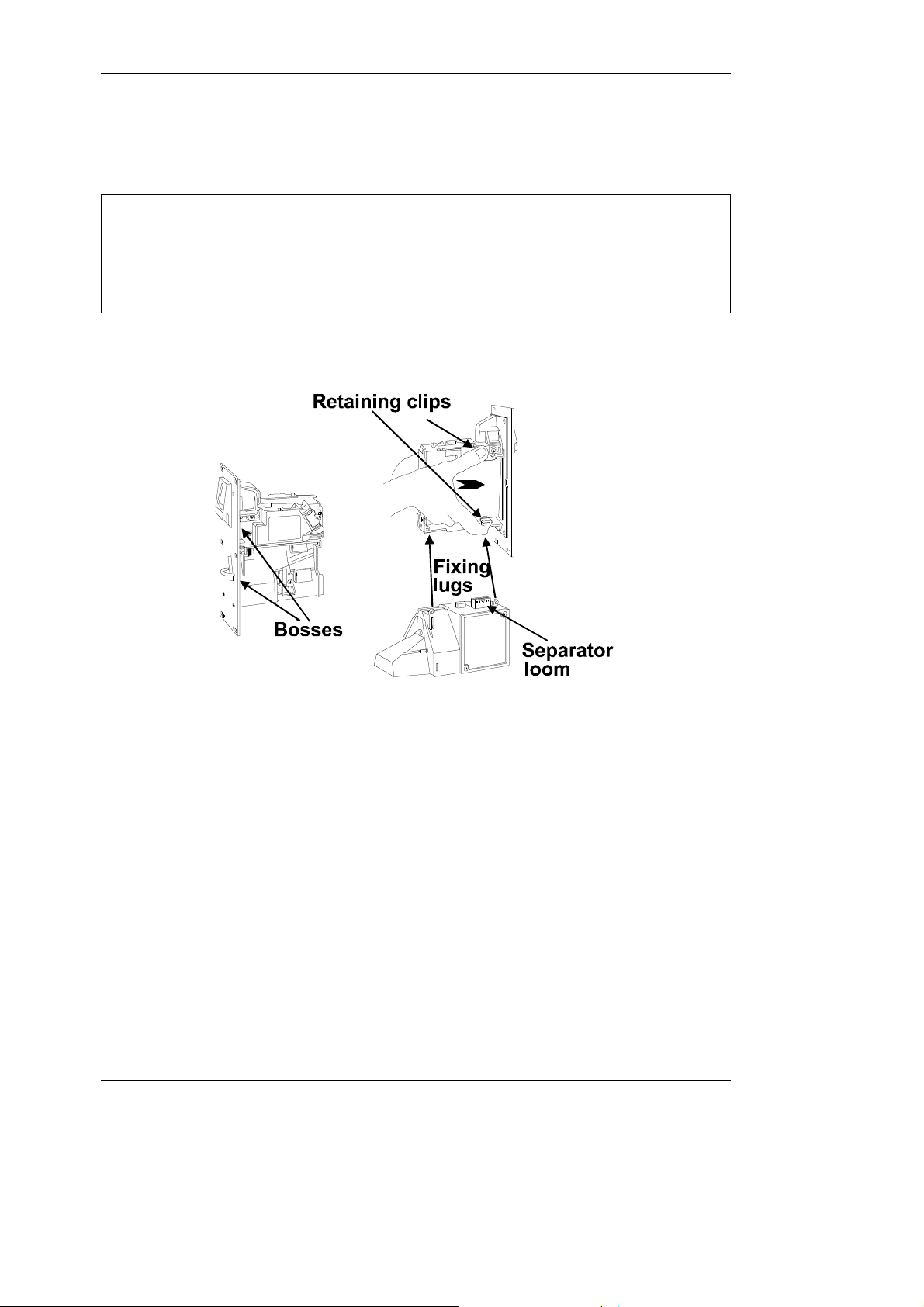
CF126 Front Entry Installation
q Connect the separator loom to the connector at the base of the validator and locate
the rectangular boss on the top of the separator into the base of the validator.
q Firmly screw the separator fixing lugs onto the rear of the validator.
q Having ensured that the front plate has a firm location onto the front of the
machine, insert the side of the validator onto the two round bosses at the rear of
the front plate and push firmly together until the two retaining clips are fully
engaged.
6 ©, Mars, Inc., 1998
Page 11

CF 126 Top Entry Installation
CashFlow® 126 and CashFlow® 129 selectors User Guide
+ When mounted into a short channel the product must be fully assembled and ready for use,
with only the machine interface loom to be connected.
q The mounting points indicated must be firmly seated into the channel and a
gap of between 2-3 mm left between the reject lever and the reject arm from
the machine. This small gap will ensure that the validator lid is able to fully
close when the reject button on the machine has been pressed and released.
The two Y-chutes already referred to can both be used with the short channel
version, but care must be taken to ensure that the gap mentioned above is
maintained between the Y-chute reject arm link and the reject lever of the coin
mechanism.
©, Mars, Inc., 1998 7
Page 12

CashFlow® 126 and CashFlow® 129 selectors User Guide
CashFlow® 129 System Installation
The system consists of a channel, Y-chute, CashFlow® 129 validator, 8-way separator,
manifold and tube collar plate.
This is supplied as a complete system, but should you need to replace any part of it do so
only in a set sequence, starting from near the top.
+ The Y-chute can, of course, be removed first, but it is not necessary to do so just to access the
other modules.
Removal of Validator and Separator
q Ensure that power is turned off, not only to the validator, but also to the Y-chute if
live.
q Dis-connect machine interface loom, and the route inhibit connector.
q Dis-engage the release catch and lift the validator and separator upwards out of
the mounting points. Pull the validator and separator forwards clear of channel.
8 ©, Mars, Inc., 1998
Page 13

Removal of Manifold and Collar Plate
CashFlow® 126 and CashFlow® 129 selectors User Guide
q The manifold is supported in position by four lugs which slot into the side plates of
the channel. It is retained there by two catches, as is the collar plate at the bottom.
Bottom section of CashFlow®® 129 system
Removal of Y-chute
q Always dis-connect the electrical connection first, if used, before removal of the
Y-chute.
q Pinch together the bottom ends of the Y-chute and lift upwards and to the right
from the channel.
Top section of CashFlow® 129 system
©, Mars, Inc., 1998 9
Page 14

CashFlow® 126 and CashFlow® 129 selectors User Guide
ACCEPTANCE AND ROUTING
When the product is successfully mounted you will need to confirm that it is set up
correctly to accept good coins/tokens and direct them to where you want them to go.
First things first
q Press and release the reject button on the machine. Confirm that the lid on the
front of the validator closes fully when the reject button is released. If it does not
close fully the validator cannot function properly.
q Test that power is on by checking that the green LED on the front of the validator is
illuminated, it will flash off once when the reject lever is pressed.
Testing for Acceptance
q Insert into the machine a selection of all the coins/tokens shown on the validator
label. Acceptance of each one will be indicated by the LED flashing off once, and if
the coin/token is outside of the programmed window it will flash off twice. If the
LED flashes three time this indicates that the coin/token has been rejected by the
validator 4th sensor. Should the LED flash off four times this indicates either a
hardware or software inhibit is being applied.
Coin Routing
q Confirm that all coins and tokens are being routed to the required exits. If they are
not refer to the Trouble Shooting section. Settings may have been made on the
machine for hopper or tube limit switches, and these must be taken into account.
q If further help is required then consult the Operators Handbook for the product or
contact either your distributor or local MEI office.
10 ©, Mars, Inc., 1998
Page 15

CashFlow® 126 and CashFlow® 129 selectors User Guide
PRODUCT FEATURES
The CashFlow® 126 and CashFlow® 129 products have the flexibility to change certain
settings such as varying the coin-set that it handles, or new routing for some of the
coins/tokens.
These changes can be carried out using the rotary data switch and the configuration
switch which are fitted uniquely to the CashFlow® 126 and CashFlow® 129 products. The
following pages show how, with the use of these switches, coins/tokens can be inhibited
or enabled, either a new individual token or a group of tokens selected and the machine
output mode changed.
In addition to these two switches there is a green diagnostic LED which signifies if any
changes you make have been successfully actioned or not.
Changes can also be made to the coin routing with the use of
a routing plug.
The routing plug is available in two forms, either ready-made
for specific applications, or do-it-yourself kits, consisting of
loose plugs and either wire links with crimps at each end or
links incorporating a sleeved IN4148 diode with crimps at each end. The diode version is
required to give protection from shorting where two separate coins are required to got to
the same exit. An illustration of how these can be assembled is shown on the next page.
Both versions are available from your distributor, who can assist you with assembly
details.
A summary follows of the way in which you can use the above features. For greater detail
of how to use all of these features you are advised to contact either your distributor or MEI
office for technical assistance.
©, Mars, Inc., 1998 11
Page 16
Inhibit 6
17IA Coin Inhibit
-
17
0V Supply
12I0V Supply
11
12
Accept Output 3
7OD Coin Output
6
7
CashFlow® 126 and CashFlow® 129 selectors User Guide
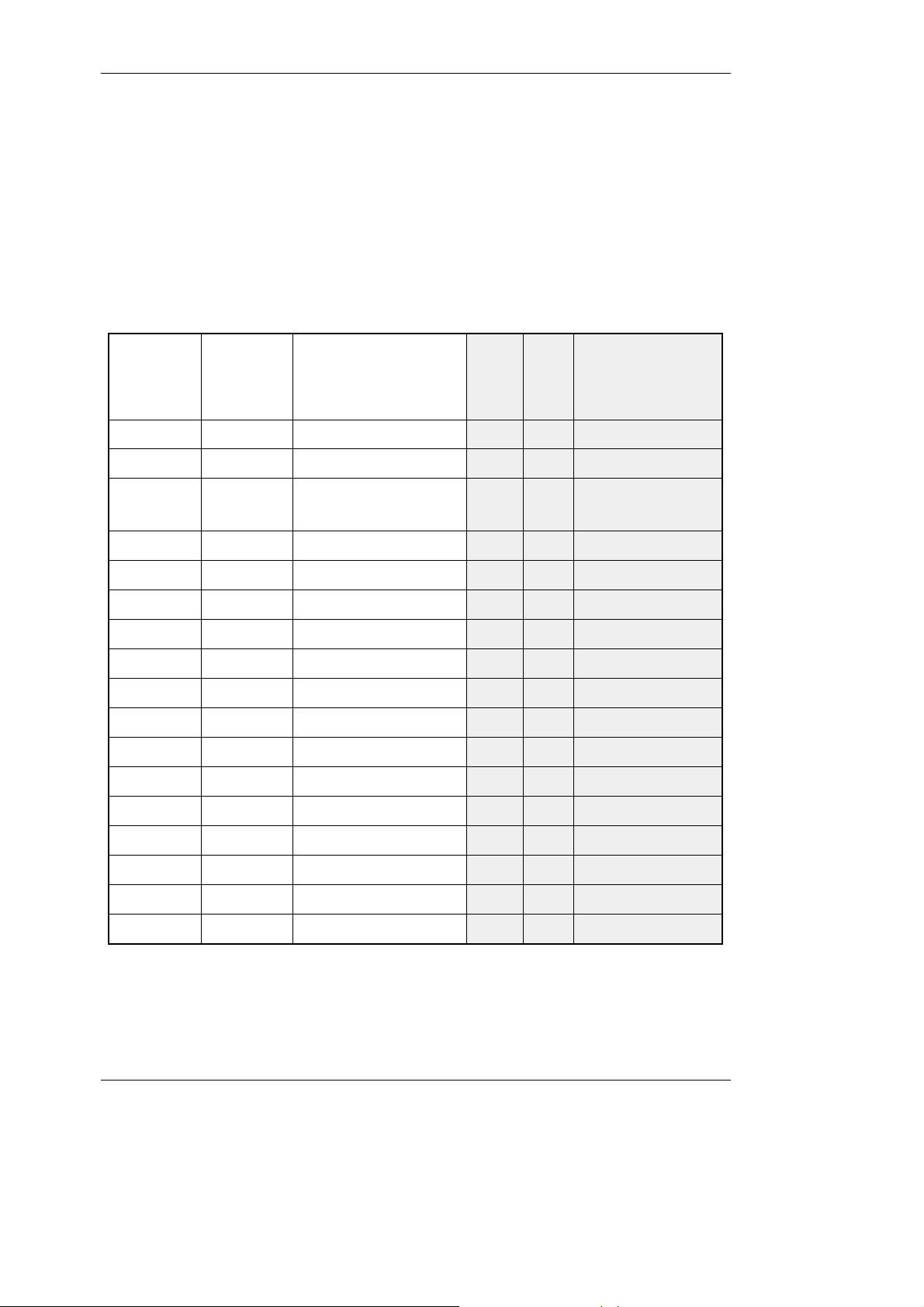
CONFIGURATION
Validator Interface Connector
The interface to the validator from the machine is exactly the same as those which apply
to the MS/ME series validators, with the exception of pin 8 of the 17-way connector
Connector 1 can accept either 15 pin or 17 pin interface connectors.
17
Way
Connector
15
Way
Connector
23
Function
Mars Compatible
Definitions
Common
Input
or
Outpu
t
PIN
No.
Function
BACTA Standard
Definition
Ident signal1OA Coin Output-1
Accept Output 52OB Coin Output12
Accept Output
3ICoin Output
Common
Accept Output 14OF Coin Output34
Polarising Key5-Polarising Key 145
Accept Output 26OE Coin Output56
Select Line8IOutput Mode Input78
Accept Output 49OC Coin Output89
Inhibit 410IC Coin Inhibit910
+12V Supply11I+12V Supply1011
12 ©, Mars, Inc., 1998
Inhibit 313ID Coin Inhibit1213
Inhibit 214IE Coin Inhibit1314
Inhibit 115IF Coin Inhibit1415
Inhibit 516IB Coin Inhibit1516
Page 17
CashFlow® 126 and CashFlow® 129 selectors User Guide
Coin A
1516Coin B
Exit C
56Exit C
Coin E
1920Coin F
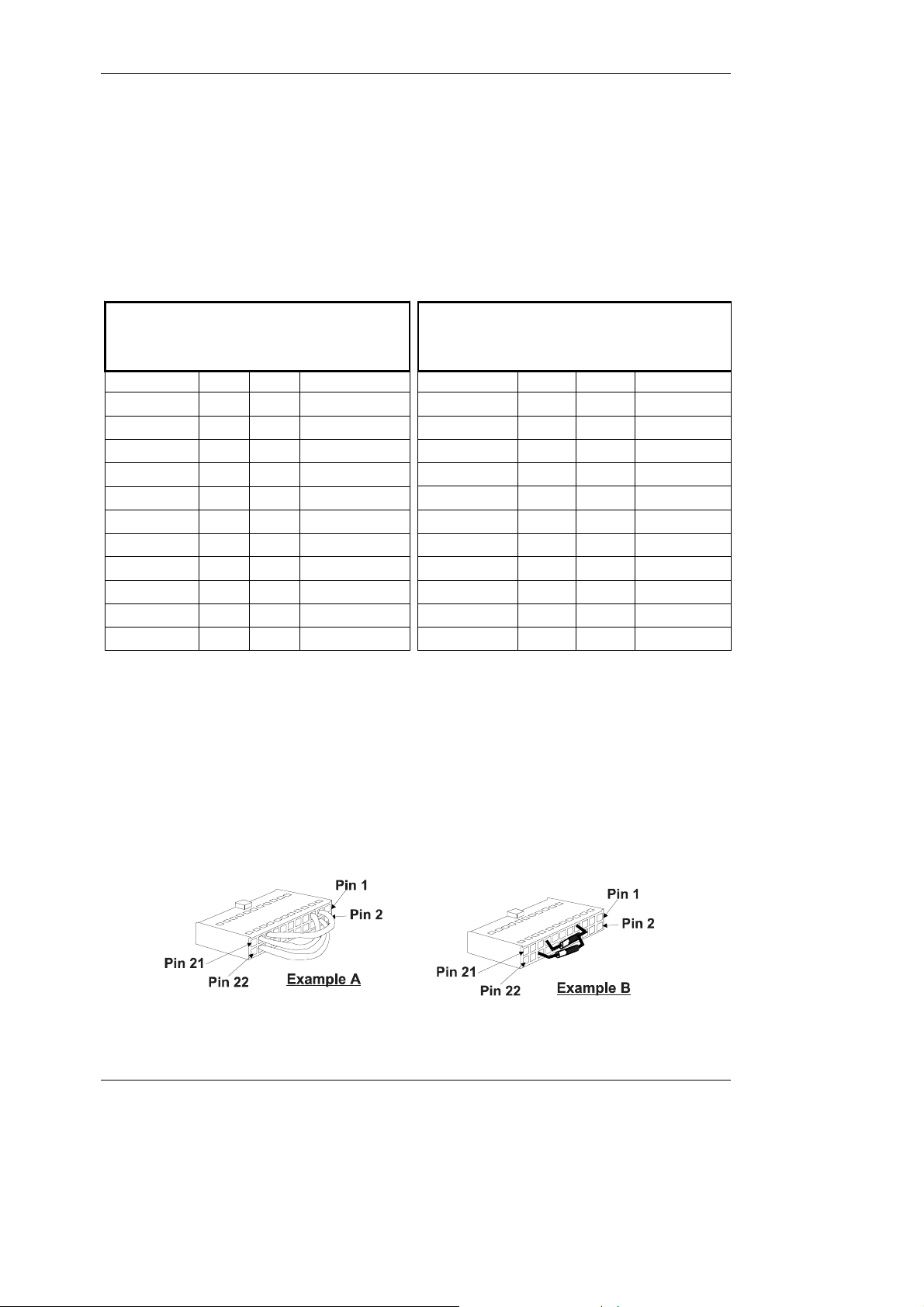
Assembling a 22-Way Routing Plug
While the links are readily inserted into the routing plug by hand without specialist tools,
care is needed to ensure that they are fitted the correct way round, particularly with the
doide version, so that the barb in the pin engages with the recess in the plug. Having
inserted a link give it a gentle tug to ensure that it has engaged with the recess.
126 Routing Plug
Pin outs and Functions
FUNCTIONPINPINFUNCTION
Coin G2122Coin H
129 Routing Plug
Pinouts and Functions
FUNCTIONPINPINFUNCTION
Coin G2122Coin H
Coin E1920Coin F
Coin C1718Coin D
Coin C1718Coin D
Coin A1516Coin B
(Exit ‘d’)1314(Exit ‘d’)
(Exit ‘c’)1112(Exit ‘c’)
(Exit ‘a’)910(Exit ‘a’)
(Exit ‘b’)78(Exit ‘b’)
Route 11314Route 1
Route 21112Route 2
Route 3910Route 3
Route 478Route 4
Route 556Route 5
Exit D34Exit D
Exit B12Exit B
Route 634Route 6
Route 712Route 7
To assemble routing plugs which will route specified UK coins to the required exits
see the examples shown.
In example A Coin C (10P) is being directed to Exit D, Coin E (50P old) to Coin Exit C and
Coin F to Exit D.
Example B shows Coin B (Token) going to Exit B and Coin E (50p old) to Exit ‘b’.
©, Mars, Inc., 1998 13
Page 18

Coin and token values as shown on the coin set label are expressed in the following text
Shaded exits are Manifold only
CashFlow® 126 and CashFlow® 129 selectors User Guide
as channels. The relative positions of these channels and coins/tokens are shown on the
table below.
Seperator Exits
129
Separator Outline
EXIT POSITIONS
Viewed from above
Manifold Outline
Position
Coin Channel/
Label Position
Channel/Coin
Value
Token 100
Token 211
5p22
10p33
20p44
50p old Tight55
50p old66
50p New77
£188
£199
£2 Tight10A
£211B
-12C
-13D
-14E
-15F
126
8
7
6
6
7
5
Reject
2
8
4
3
3
2
1
N.B. Clear exits are Separator only
1
14 ©, Mars, Inc., 1998
5
D
4
(d)
A
(a)
C
(c)
B
(b)
Page 19
(c)Divert route 2
2
CashFlow® 126 and CashFlow® 129 selectors User Guide
Route Inhibit Connector
The function of the route Inhibit Connector is to signal when specific exits, external to the
product, are in a “Full” condition. Signals from the machine ensure that, while the “Full”
condition continues, further coins/tokens directed to that exit will be re-routed to an
alternative exit. The instruction as to which alternative exits can be used will normally
come from the routing plug.
+ In order to inhibit a particular route, 0V must be applied to its respective pin.
+ An alternative route must always be of a lower priority
126129PIN
(d)Divert route 11
(a)Divert route 33
(b)Divert route 44
CDivert route 55
DDivert route 66
BDivert route 77
Not definedNot defined8
0v0v9
Priority
Highest
Lowest
©, Mars, Inc., 1998 15
Page 20
CashFlow® 126 and CashFlow® 129 selectors User Guide
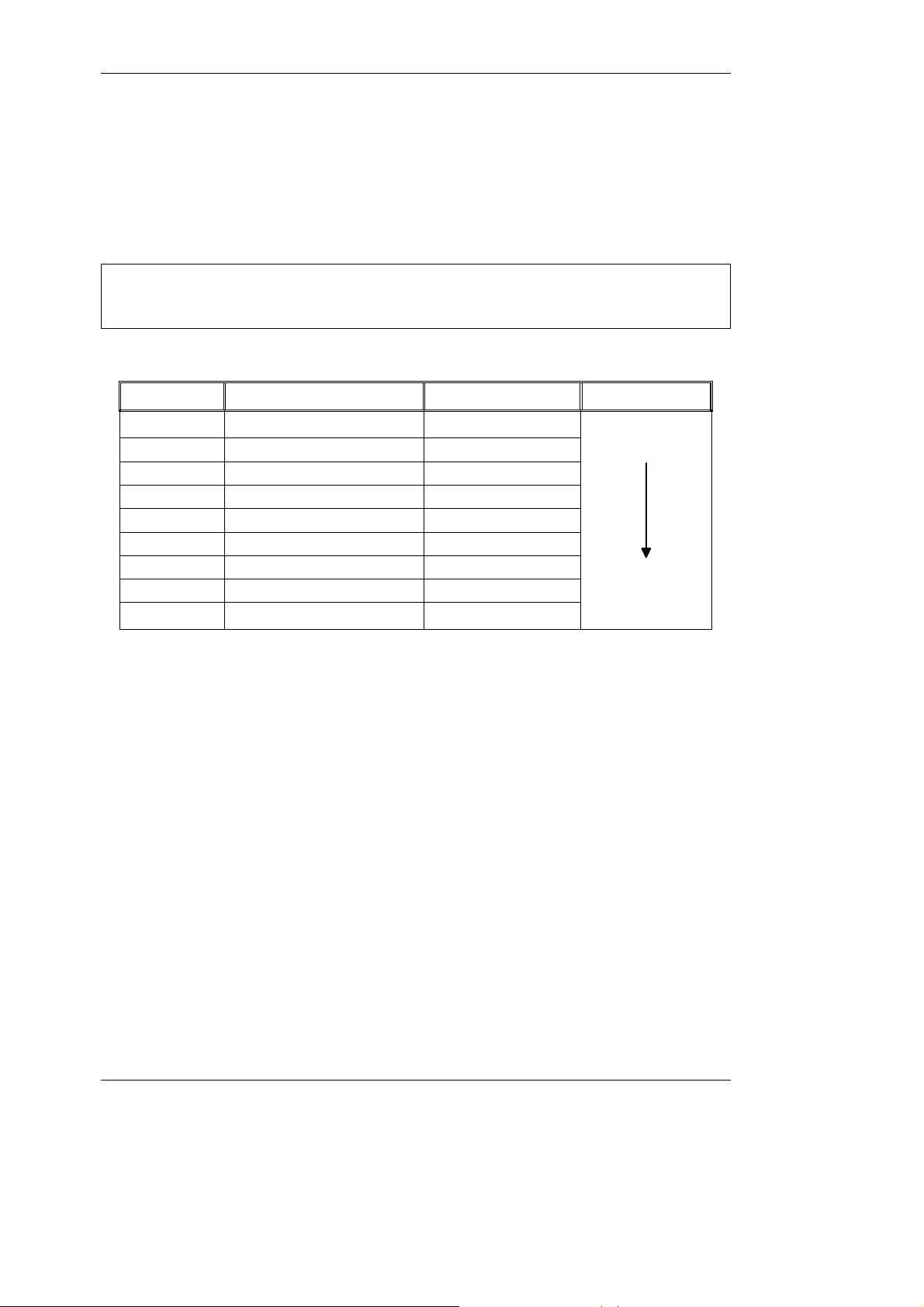
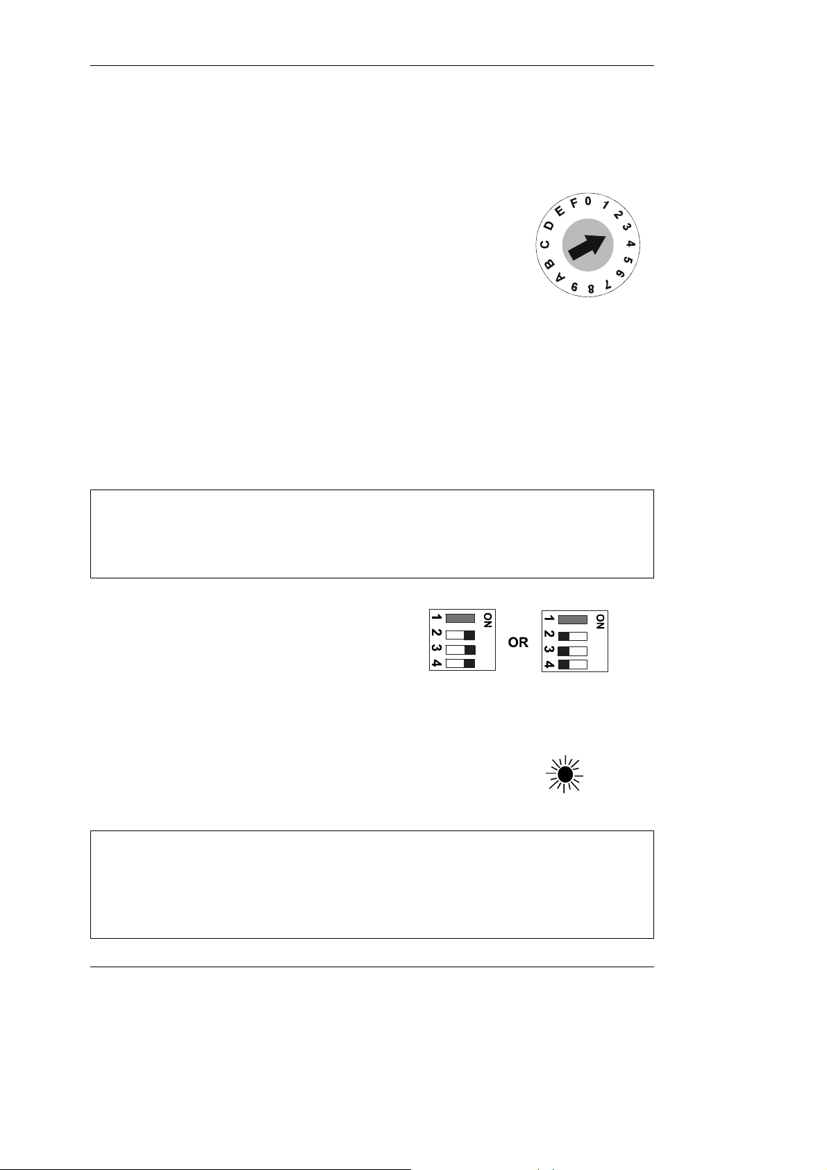
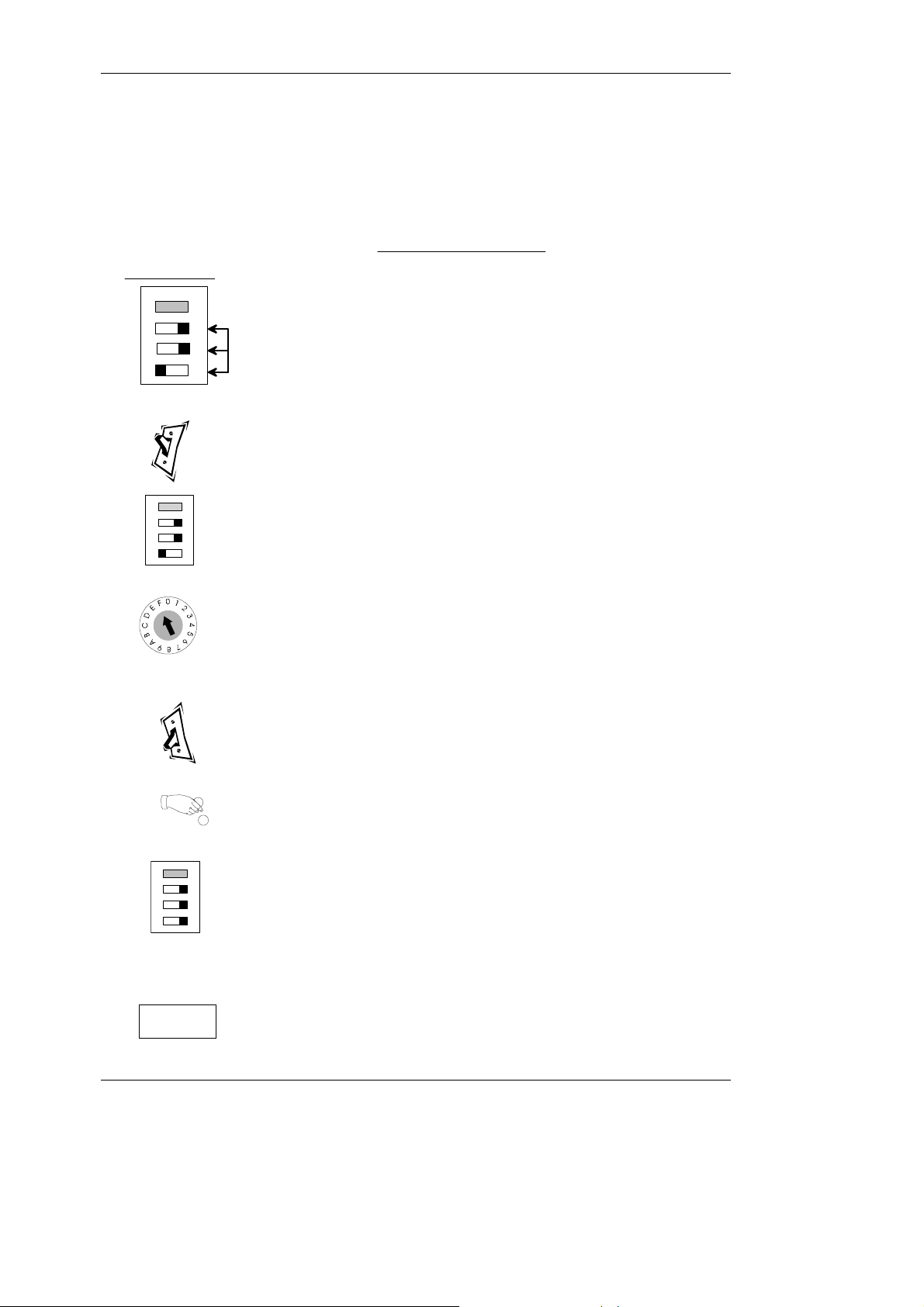
Using the Rotary Data Switch and Configuration
Switches
Rotary Data Switch
The rotary data switch is used in conjunction with the
configuration switches. By pointing the arrow in the middle of
the switch, using a fine screwdriver, data can be entered into
the product. In Normal Operation mode the position of the arrow
is not critical to correct operation.
Configuration Teach Switches
These switches can be set to a series of positions which enable the product configuration
to be changed.
When teach modes are to be entered first SWITCH POWER OFF to
the unit, or an un-intended action could be set.
The example given here, with both the rotary data switch and the
configuration switch settings, is to enable channel 3 in the coin set.
+ Wherever in the examples that follow the switch is shown as hatched grey (usually switch 1) it
indicates that it does not matter if the switch is in the ON or OFF position. Switch 1 only features
in the settings for Alarm Enable when it must be in the ON position. When it is in the OFF
position the Alarm function is NOT active.
q After making any changes the
configuration switches 2, 3, and 4
MUST always return to either of the
Normal Operation positions shown
here.
Diagnostic LED
q The LED will illuminate to indicate that the product is
powered up, and in addition will give various sequences of
flashes to confirm the acceptance or rejection status of
coins/tokens.
+ Flash Sequence:Constantly ON Validator Power On
1 Flash Coin accepted / Reject lever pressed
2 Flashes Coin not recognised and rejected
3 Flashes Coin rejected by validator 4th sensor.
4 Flashes Coin recognised but not accepted due to inhibit setting
16 ©, Mars, Inc., 1998
Page 21
CashFlow® 126 and CashFlow® 129 selectors User Guide
END
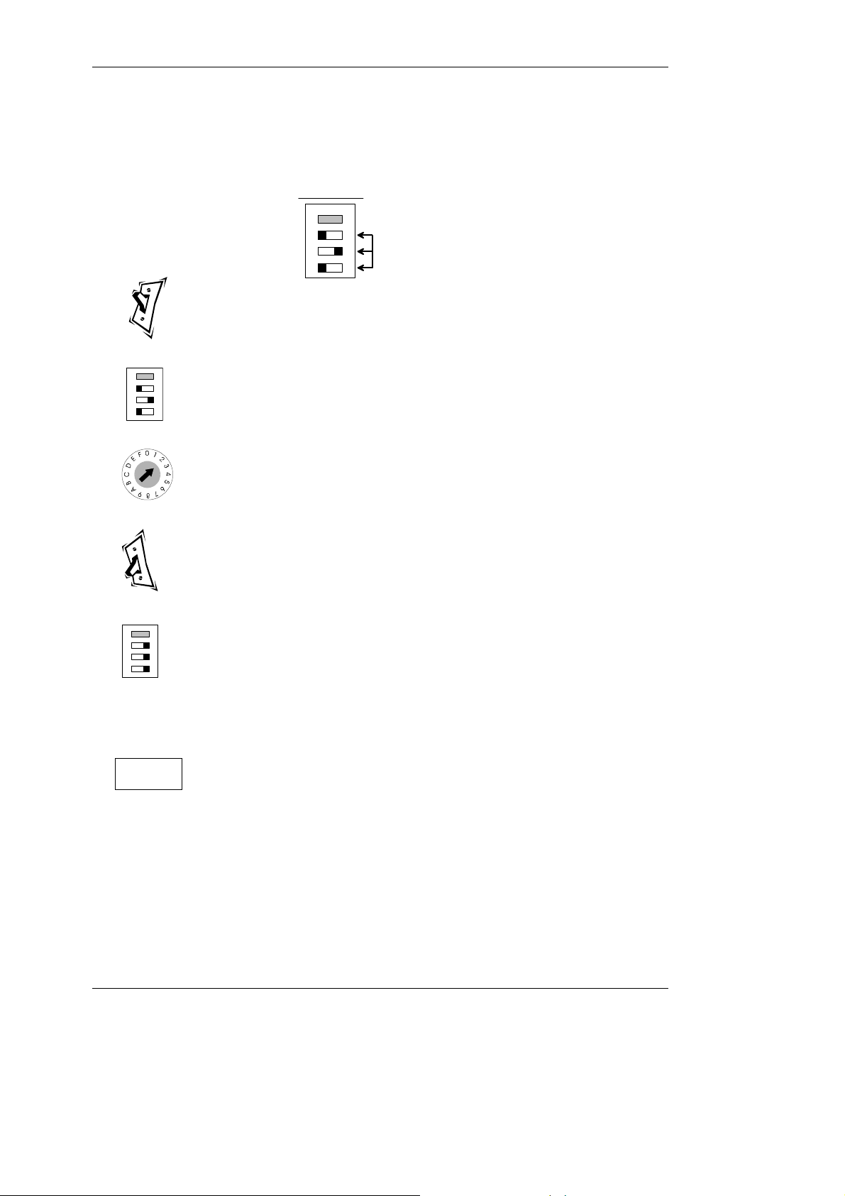
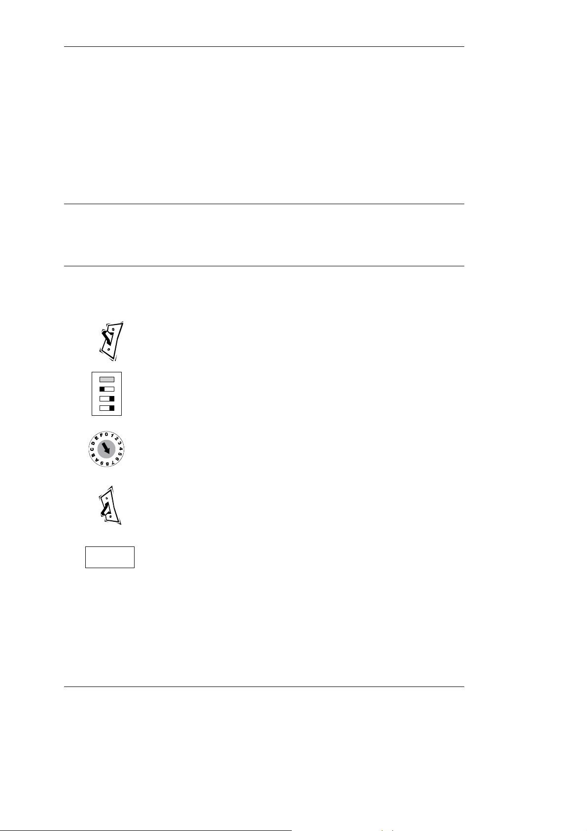
Product Configuration - Inhibiting coins or tokens
Example:- To inhibit channel 2 (the 5p coin) on your validator follow
these simple steps.
Channel Inhibit
ON
1 2 3 4
Set switches 2, 3 and 4
as shown here.
1. Switch Validator Power OFF.
ON
1
2 3 4
2. Set 4 Way Switches to Inhibit Teach.
3. Set Rotary Switch Dial to the appropriate channel.
(Channel No.2 for the 5p In this instance).
4. Switch Validator Power ON (LED will flash).
ON
1
5. Set switches 2, 3 & 4 to ON.
2 3 4
(LED will stop flashing and stay on).
The Rotary Switch settings can be left unchanged.
6. The chosen coin is now inhibited and the product
is ready for normal operation. For each additional
channel to be inhibited repeat process from 1 above.
©, Mars, Inc., 1998 17
Page 22
CashFlow® 126 and CashFlow® 129 selectors User Guide
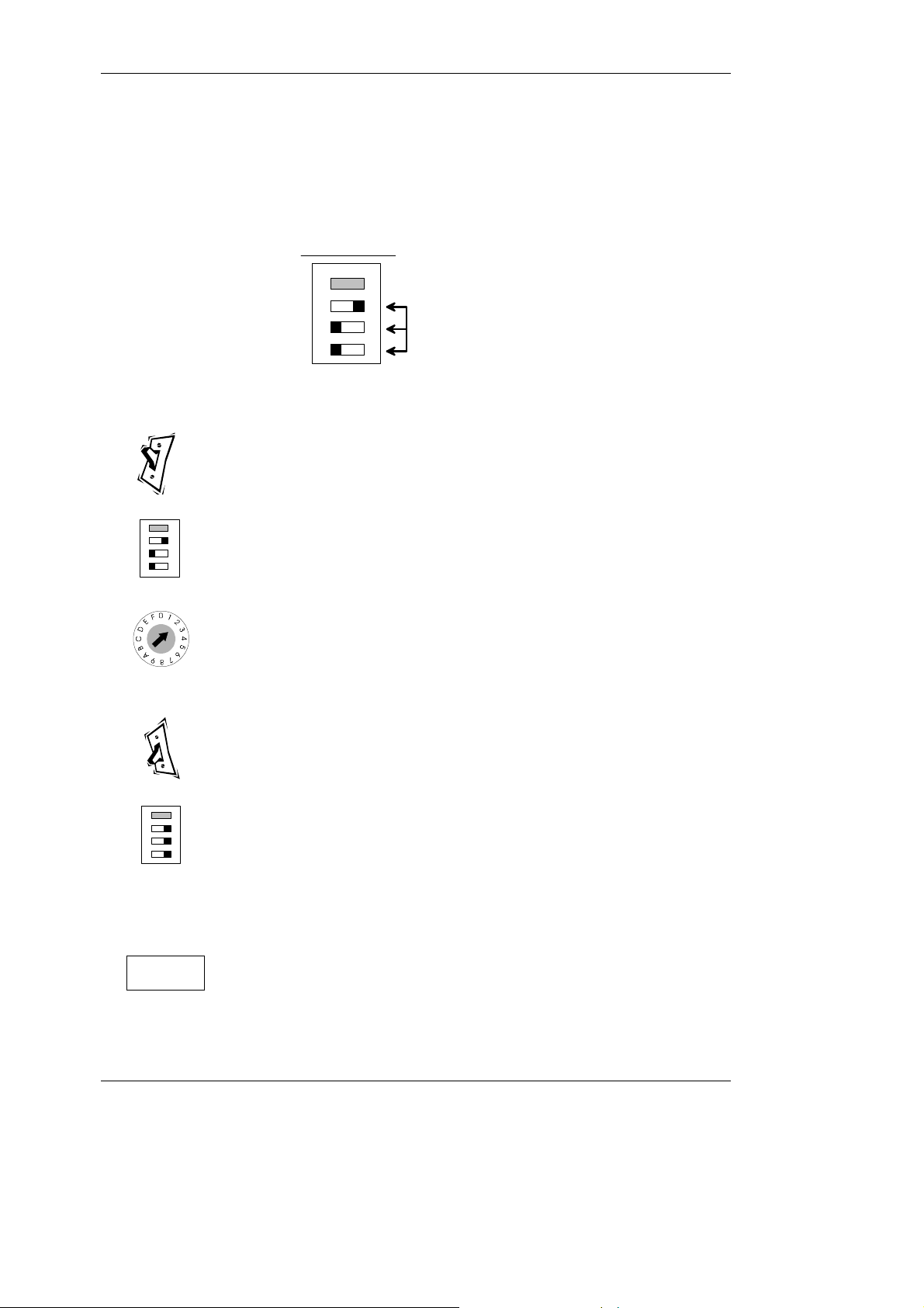
Product Configuration - Enabling coins or tokens
Example:- To enable channel 2 (the 5p coin in this instance) on your
validator follow these simple steps.
Channel Enable
1 2 3 4
1. Switch Validator Power OFF.
ON
Set switches 2, 3 and 4
as shown here.
ON
1
2 3 4
2. Set 4 Way switches to Enable Teach.
3. Set Rotary Switch Dial to the appropriate channel.
(Channel No.2 for the 5p In this instance)
4. Switch Validator Power ON (LED will flash).
ON
1
2 3 4
5. Set switches 2, 3 & 4 to ON.
(LED will stop flashing and stay on).
The Rotary Switch settings can be left unchanged.
6 The chosen coin is now enabled and the product is
END
ready for normal operation. For each additional
channel to be inhibited repeat process from 1 above.
18 ©, Mars, Inc., 1998
Page 23
CashFlow® 126 and CashFlow® 129 selectors User Guide
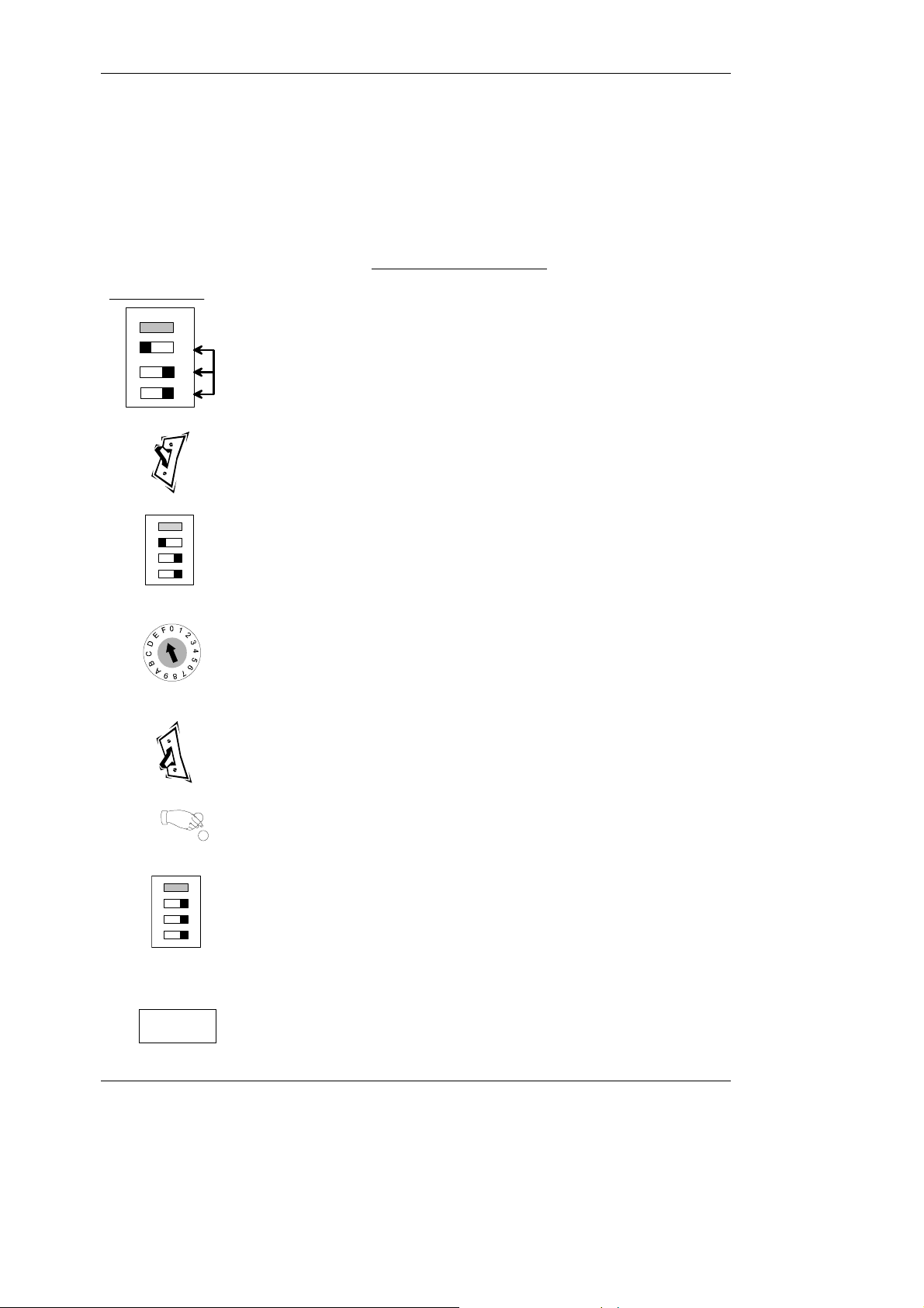
Product Configuration - teaching a new token,
channel 0
Example:- To Teach a Token (with standard window limits) into channel
0 follow these simple steps.
LED Flash Codes for Tokens:
Channel Enable
1 2 3 4
ON
Set switches 2, 3 and 4
as shown here.
2 flashes = No activity detected (for last 30 seconds)
3 flashes = Insufficient Tokens (10 min.)
4 flashes = Invalid Rotary Switch (setting E or F)
5 flashes = Token thickness outside allowable limits
6 flashes = Token diameter outside allowable limits
7 or 8 flashes = Token material outside allowable limits
1. Switch Validator Power OFF.
ON
1 2 3 4
2. Set 4 Way switches to Token Teach.
3. Set Rotary Switch Dial to position F (standard
window limits).
(Position E will teach tight token window limits)
4. Switch Validator Power ON (LED will Flash).
+5. Drop between 10 and 20 Tokens.
ON
6. Return switches to Normal Operation. (LED
1
2 3 4
should stop flashing and stay on to indicate a
successful change). If the LED continues to
flash this indicates a failure to teach the token.
If needed repeat the process from step 1.
7. Token successfully taught & programmed
END
into Channel 0.
©, Mars, Inc., 1998 19
Page 24
CashFlow® 126 and CashFlow® 129 selectors User Guide
7 or 8 flashes = Token material outside allowable limits
Product Configuration - teaching a new token,
channel 1
Example:- To Teach a Token (with standard window limits) into channel
1 follow these simple steps.
LED Flash Codes for Tokens:
Channel Enable
1 2 3 4
ON
Set switches 2, 3 and 4
as shown here.
2 flashes = No activity detected (for last 30 seconds)
3 flashes = Insufficient Tokens (10 min.)
4 flashes = Invalid Rotary Switch (setting E or F)
5 flashes = Token thickness outside allowable limits
6 flashes = Token diameter outside allowable limits
1. Switch Validator Power OFF.
ON
1 2 3 4
2. Set 4 Way switches to Token Teach.
3. Set Rotary Switch Dial to position F ((standard
window limits). ).
(Position E will teach narrow slug windows)
4. Switch Validator Power ON (LED will Flash).
5. Drop between 10 and 20 Tokens.
6. Return switches to Normal Operation. (LED
ON
1
2 3 4
should stop flashing and stay on to indicate a
successful change). If the LED continues to
flash this indicates a failure to teach the token.
If needed repeat the process from step 1.
7. Token successfully taught & programmed
END
into Channel 1.
20 ©, Mars, Inc., 1998
Page 25
CashFlow® 126 and CashFlow® 129 selectors User Guide
Product Configuration -
Selecting a pre-programmed token group to be used
in channel 0
14 token groups are already programmed into the product. This feature
allows a defined token group to be accepted.
v NOTE: Each token group selected is automatically copied to channel 0.
Refer to the Appendix at the end of the book for further details of token
groupings.
Example:- To select Token Group 7 on your validator follow these
simple steps.
1. Switch Validator Power OFF.
ON
1 2 3 4
2. Set 4 Way Switches to Select Token Group.
3. Set Rotary Switch Dial to the appropriate
Channel. (Token group 7 in this example).
4. Switch Validator Power ON (LED will flash).
5. Return Switches to Normal Operation
END
(LED stops flashing and stays on to indicate
successful change. Token Group 7 successfully
selected and programmed into Channel 0.
©, Mars, Inc., 1998 21
Page 26

CashFlow® 126 and CashFlow® 129 selectors User Guide
Product Configuration -
Selecting a pre-programmed token group to be used
in channel 1
14 token groups are already programmed into the product. This feature
allows a defined token group to be accepted.
v NOTE: Each token group selected is automatically copied to channel 1.
Refer to the Appendix at the end of the book for further details of token
groupings.
Example:- To select Token Group 7 on your validator follow these
simple steps.
1. Switch Validator Power OFF.
ON
1 2 3 4
2. Set 4 Way Switches to Select Token Group.
3. Setting Rotary Switch Dial to position 7 selects
MHG token group
4. Switch Validator Power ON (LED will flash).
5. Return Switches to Normal Operation
END
(LED stops flashing and stays on to indicate
successful change. Token Group 7 successfully
selected and programmed into Channel 1.
22 ©, Mars, Inc., 1998
Page 27

CashFlow® 126 and CashFlow® 129 selectors User Guide
Position D = Fixed Parallel mode
Position F = Automatic mode
END
Product Configuration Changing the machine output mode
To change the coin output interface to Fixed Binary Coded Output
(BCO) use these simple steps. For BCO mode set the rotary data switch
to position C , to D for Fixed Parallel mode and F for Automatic
mode.
v NOTE: The product will normally be supplied in Automatic mode. This
will automatically configure to most machines through the Mode Select
feature. Some gaming machines have pre-BACTA standard Binary code
software and in this case the coin mechanism should be set to fixed
Parallel mode.
Example:- To set mode to Binary Coded Output
1 2 3 4
ON
Set switches 2, 3 and 4
as shown here.
Position C = Fixed B.C.O. mode.
1. Switch Validator Power OFF.
ON
1 2 3 4
2. Set 4 Way switches to Output Mode Teach.
3. Set Rotary Switch Dial to appropriate position.
(Position C in this example).
4. Switch Validator Power ON (LED will Flash).
ON
1
5. Set switches 2, 3 & 4 to ON. (LED will stop
2 3 4
flashing and stay on).
Leave the Rotary Switch settings as they are.
6. Product is now ready for use with the chosen
machine interface.
©, Mars, Inc., 1998 23
Page 28

CashFlow® 126 and CashFlow® 129 selectors User Guide
MAINTENANCE
+ The practical maintenance that can be carried out is limited to cleaning the areas of the
validator that the coins travel through, and the replacement of the coin entry liner if it becomes
worn. All other servicing is carried out through your distributor.
The cleaning should be carried out on a regular basis of at least once a month, but, if you
have to visit the validator outside of that routine, it is worth while doing it then as well.
The shaded areas shown below, plus the back of the reject cover, are those to be cared
for.
The coin entry liner is accessed by unscrewing the coin entry moulding at the top of the
validator. The coin entry liner can then be eased off with the aid of a fine screwdriver, and
a replacement slid into place.
q Cleaning and maintenance must only be carried out by suitably trained personnel.
q Cleaning must only be carried out after power has been removed from the product.
q Never use a cleaner containing solvents, scrapers or abrasive materials.
q Never apply water or cleansers directly onto the product. Always apply them to a
clean cloth first, and not too liberally, so that the cloth used is only moist.
APPENDIX
24 ©, Mars, Inc., 1998
Page 29

0
Reserved
16FN-Plate
Steel
15EN-Plate
Steel
14DN-P
Brass &
13CBrass &
N-Plate
Brass
3
12BDefault (Brass-Wide)
333
3
11AOversized Token
108Paymaster
87MHG
76Stretton
Leisure
64LMS
333
43Ralin
& Thomas
333
32BFS
21Rank Leisure
1ECBA
ME token group
Token Grouping Compatibility
CashFlow® 126 and CashFlow® 129 selectors User Guide
Product Revision
The revision level of the 126/129 product can be confirmed from a label on the left side of
the product. There are two levels of digits and bar-code markings on the label, and the
fifth and sixth digits on the lower numbers indicate the product level.
For example; if the label read 1773G322580 the revision level would be G3.
Do not use the label on the right side of the product for reference of the revision level.
ME Token
groups
LINK settings
(links inserted = 3)
333
3
33
33
33
3
333
33
3
Token Type or
Operator
Oversized
CF126/129
token group
Rotary switch
position
©, Mars, Inc., 1998 25
Page 30

CashFlow® 126 and CashFlow® 129 selectors User Guide
PRODUCT SUPPORT
In addition to the MEI offices around the world an international network of Distributors and
Approved Service Centres can offer you technical support and other services as well.
These services include repairs, re-programming of your CashFlow® products with new
coinsets, replacing damaged modules, and the supply of a range of spare parts.
In the U.K. these can be obtained from the following:
BRENT LEISURE SPARES LTD.
Unit 5, Acton Vale Industrial Estate
The Vale, Acton
London W3 7QE
Contact: Steve Ansell
Telephone: 0181 - 324 - 6000
EUROCOIN LTD
Fortune House
Moxon Street
Barnet
Herts
Contact: Ray Moore
Telephone: 0181 - 449 - 0077
MICRO ELECTRONIC SERVICES (M.E.S.)
7 Aircraft Esplanade
Farnborough
Hampshire GU14 6TG
Contact: Mike Clokie
Telephone: 01252 375302
(Service Centre only)
©, Mars, Inc., 1998 26
Page 31

Helping you deliver
YOUR MEI REPRESENTATIVE
 Loading...