

Page 1
GE Transformers
®
COMPONENT
ARS SERIES
M
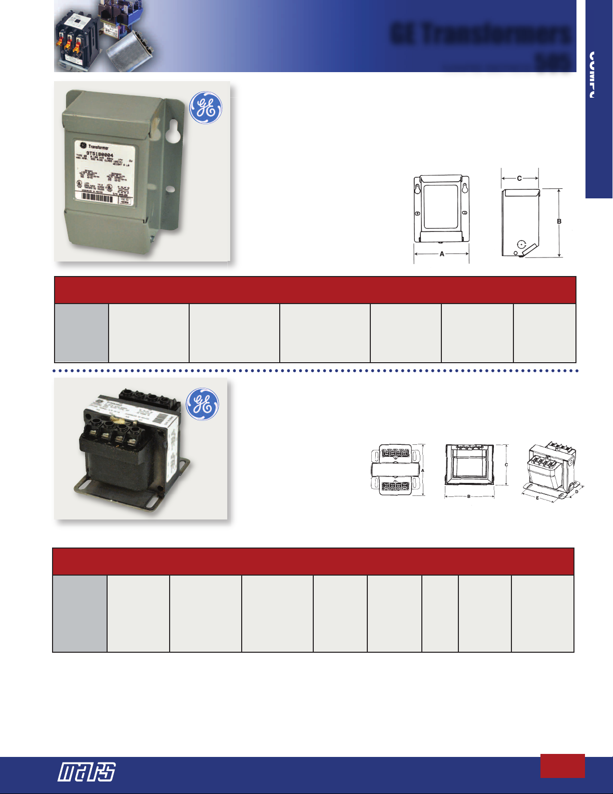
Single Phase
Dry Type Transformers
GE dry type transformers are designed for low voltage power distribution. They are made
of a heavy gauge steel construction, suitable for indoor or outdoor NEMA 3R use in
commercial and industrial power applications. Knockouts are provided for easy wiring.A
schematic connection diagram is located on the enclosure nameplate for quick referral.
Features:
• Single phase
• 6 inch leads - clearly marked
• 60 Hertz
• Indoor/outdoor NEMA 3R
50530
MARS KVA DIMENSIONS
NO. RATING PRIMARY SECONDARY ABC
50530 .10 240/480 120/240 5.125 6.375 3.25
50531 .15 240/480 120/240 6.125 7.375 4.25
50533 .50 240/480 120/240 6.875 8.375 4.875
50534 .75 240/480 120/240 7.875 9.625 5.50
50535 1.00 240/480 120/240 7.875 9.625 5.50
50536 1.50 240/480 120/240 9.375 11.125 6.7188
• UL listed
• CSA certified
front view
505
side view
Type Ip Core and Coil Transformers
GE type IP transformers are core and coil units designed for industrial control, panel board,
HVAC and general purpose applications. They conform to ANSI C89.2, and are UL listed
and CSA certified. These transformers are lightweight, small and designed for minimum
mounting dimensions.
Features:
• 60 Hertz
• Encapsulated thru 500VA
• Control power applications
50502
Encapsulated
MARS CONT. DIMENSIONS
NO. KVA PRIMARY SECONDARY ABCD E
50502 .075 240/480 120/240 4.22 3.29 2.79 2.41 2.50
50503 .100 240/480 120/240 4.17 4.04 3.29 2.16 3.12
50504 .150 240/480 120/240 4.67 4.04 3.29 2.66 3.12
50505 .200 240/480 120/240 4.92 4.04 3.29 2.91 3.12
50506 .250 240/480 120/240 5.17 4.04 3.29 3.16 3.12
50507 .300 240/480 120/240 5.17 4.04 3.29 3.16 3.12
50508 .375 240/480 120/240 5.67 4.04 3.29 3.66 3.12
50509 .500 240/480 120/240 5.82 4.79 3.92 3.31 3.79
Step-by-Step Selection of Core and CoilTransformers:
1. Determine the input voltage, output voltage and frequency.
2. Determine the continuous power (VA) drawn by each load device. Calculate the maximum continuous power of all load devices that could be
energized at the same time.
3. Determine if any of the load devices are voltage sensitive. NEMA standards require electromagnetic components to operate reliably at 85% of rated
voltage. This includes devices such as contactors, relays and solenoids. For applications with voltage sensitive devices, determine the inrush current of
each load device. Inrush is the power (VA) drawn by a device the instant it is energized. Electromechanical devices have an inrush from 3 to 10 times
their continuous power rating. The inrush of resistive devices is the same as their continuous power rating. Calculate the maximum inrush power. This
is the inrush of all devices being energized at a given instant, plus the continuous power of all devices already energized. A number of load device
combinations may have to be examined to determine which produces the maximum inrush current.
• UL listed, UL-506 File E2739
• CSA certified,
C22.2 Number 66, File 3272
• 50 Hertz available on special order basis
top view front view
Encapsulated Style Views
The largest selection of motors, components, and accessories for the HVAC/R Industry
C-73
 Loading...