

Page 1

IC Radio Standards Specification: RSS-247
Certification Exhibit
FCC ID: SJS-400099WH
IC: 5379A-400099WH
FCC Rule Part: 15.247
ACS Project Number: 16-0481
Manufacturer: MARS Company
Model: 400099WH
Manual
5015 B.U. Bowman Drive Buford, GA 30518 USA Voice: 770-831-8048 Fax: 770-831-8598
Page 2

MARS SmartTransmitter MK-I/II
MARS SmartTransmitter VHP
FlowBridge FlowCast
Installation and Programming Guide
Page 3

Revision 1.E (CM)
January 2017
MARS Company
A Division of OW Investors, LLC
sales@marswater.com
800.782.5268
Page 4

Table of Contents
Table of Contents
1
Introduction
3
Connecting to a Meter
4
Wiring Configurations
5
Programming Configurations - Overview
7
MK-I/II Programming Configurations - Step-by-Step Guide
8
MK-I/II Programming Configurations - Parameters Explained
9
MK-I/II Programming Configurations – Meter Type Settings
10
VHP Programming Configurations - Step-by-Step Guide
12
VHP Programming Configurations - Parameters Explained
14
VHP Programming Configurations – Meter Type Settings
15
Troubleshooting
17
Contact Us
19
Information to the User (FCC Information)
21
Page 1 of 21
Page 5

Page 2 of 21
Page 6

Introduction
Page 3 of 21
Welcome to the exciting world of MARS Automated Meter Reading (AMR) Solutions. In the following
pages we will learn how to connect and program a MARS SmartTransmitter MK-I/II, a MARS
SmartTransmitter VHP (Very High Power), a FlowBridge FlowCast, and to perform occasional
troubleshooting.
There are a few points to remember while reading through the manual that can potentially help avoid
some common mistakes, and also give suggestions to help streamline the process of installing MARS
AMR.
• There are various materials that may be needed for each task, which are presented in
the beginning of each section. It is recommended that you have these nearby.
• Notes are listed in italics next to or underneath the section they are referring to. They
will list suggestions or offer advice on the adjacent topic.
• Sections in BOLD letters must be followed exactly, otherwise device operation will be
adversely affected or the manufacturer’s warranty will be voided.
• Underlined items are references to other sections of this manual.
As always, feel free to refer to the Contact Us section of the manual to call or email MARS if you have
any questions or if you would like additional information.
Page 7

Connecting to a Meter
Page 4 of 21
Materials Needed
• MARS SmartTransmitter/FlowBridge FlowCast
• Meter with AMR output
• Gel Caps with Gel Cap Tool (optional)
• Wire Strippers (optional)
• Screwdriver (optional)
• Mounting Equipment (optional)
Depending on the installation environment, whether it is inside of a meter pit or on a wall, the materials
needed may differ slightly as a pit mounted SmartTransmitter/FlowBridge FlowCast installation may
require a pit mount bracket or AMR-ready pit lid. This is installation specific, and will vary between
installations.
For a meter with screw terminals available for AMR output, wire strippers and a screwdriver
will be required. Use the wire strippers to ensure there is enough bare wire to make reliable
contact with the screw terminals. Then use the screwdriver to attach each wire to its respective
terminal, as outlined in MARS SmartTransmitter/FlowBridge FlowCast Wiring Configurations.
For a meter with a pre-wired lead, wire strippers will be needed to remove the outer jacket on
the lead and Gel Caps are recommended by MARS to attach the SmartTransmitter/FlowBridge
FlowCast to the meter. First, remove the outer jacket on the pre-wired lead. When removing
the outer jacket, do not strip the inner 2 or 3 wires. These should not be stripped as this will
case unreliable performance. Once the outer jacket is removed, use the Gel Caps and Gel Cap
Tool to connect the 2 or 3 wire leads to their respective wire on the MARS
SmartTransmitter/FlowBridge FlowCast, as outlined in MARS SmartTransmitter/FlowBridge
FlowCast Wiring Configurations.
Once these connections are made and the installation environment is appropriately prepared with any
additional equipment, the MARS SmartTransmitter/FlowBridge FlowCast is ready to be programmed.
Page 8
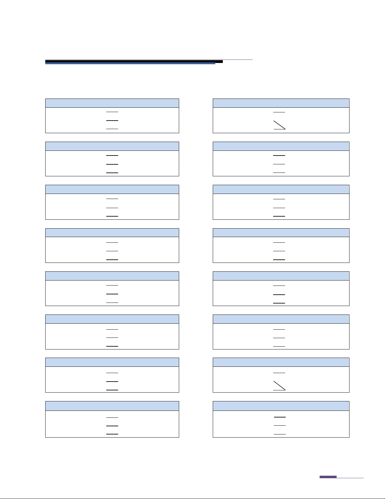
Wiring Configurations
MARS Encoder
Master Meter / 2-Wire Pulse/Generator Meter
Radio Green
Meter Green
Radio Green
Meter Red
Radio Red
Meter Red Radio Red
(3-wire Gel Cap)
Radio Black
Meter Black
Radio Black
Meter Black
Sensus Encoder
Hersey Encoder
Radio Green
Meter Green
Radio Green
Meter Green
Radio Red
Meter Red Radio Red
Meter Red
Radio Black
Meter Black
Radio Black
Meter Black
Neptune AutoRead
Neptune ProRead
Radio Green
Meter Red
Radio Green
Meter Red
Radio Red
Meter Black Radio Red
Meter Black
Radio Black
Meter Green
Radio Black
Meter Green
Elster AMCO Absolute Encoder (InVISION)
Neptune ARB V
Radio Green
Meter Red
Radio Green
Meter Red
Radio Red
Meter Green Radio Red
Meter Black
Radio Black
Meter Black
Radio Black
Meter Green
AMCO / ABB / Kent Scancoder
Elster AMCO Digital Register (pulse)
Radio Green
Meter Red
Radio Green
Meter Black
Radio Red
Meter Green Radio Red
Meter Green
Radio Black
Meter Black
Radio Black
Meter Red
Severn Trent – First Generation
Severn Trent – Second Generation
Radio Green
Meter Terminal 3
Radio Green
Meter Green
Radio Red
Meter Terminal 1
Radio Red
Meter Red
Radio Black
Meter Terminal 5
Radio Black
Meter Black
Badger ADE
Badger RTR
Radio Green
Meter Green
Radio Green
Meter Red
Radio Red
Meter Red Radio Red
(3-wire Gel Cap)
Radio Black
Meter Black
Radio Black
Meter Black
3+ -Wire Pulse/Generator Meter
Elster AMCO V-100 PSMT
Radio Green
Meter Signal Wire
Radio Green
Meter Red
Radio Red
Meter Tamper Wire
Radio Red
Meter Yellow
Radio Black
Meter Commons
Radio Black
Meter Black & Blue
Page 5 of 21
The diagrams below show the connections that must be made for each different type of meter. These
must be made correctly for the system to function normally. Unless directed otherwise by MARS or
MARS authorized personnel, follow these wiring instructions.
Page 9

Pit Mount MK – II / VHP
Wall Mount MK - II / VHP
MK - I SmartTransmitter
Page 6 of 21
Inductive Coil Locations
FlowBridge FlowCast /
SmartTransmitter
MK-IV
SmartTransmitter
Center SmartReader nozzle on these points.
Page 10

Programming Configurations - Overview
Page 7 of 21
The MARS SmartTransmitter and the FlowBridge FlowCast are programmed via an inductive coil and the
parameters are set using the MARS SmartReader handheld device. The software that is involved is very
different between the traditional MK-I or II and the VHP MARS SmartTransmitter. If you are unsure if
the proper software is installed, please refer to the Contact Us section of this manual and call MARS to
confirm.
The FlowBridge FlowCast can be programmed to be compatible with either the MK-I/II instructions or
VHP instructions outlined in this manual. As this is set by MARS during manufacture, please refer to
MARS to determine which configuration steps must be followed.
Before programming a MARS SmartTransmitter or FlowBridge FlowCast, be sure the SmartReader is fully
charged. The center of the black nozzle on the SmartReader must be centered over the locations
(shown on the left) when a function is being processed, and the center of the black nozzle of the
SmartReader MUST be flush with the SmartTransmitter/FlowBridge FlowCast housing. The
SmartReader can NOT be moved or pulled away from the SmartTransmitter/FlowBridge FlowCast
until the function in process is complete. When the function is complete, the light on the rear of the
SmartReader will stop flashing and the device will emit either an escalating tone (low to high) with a
solid green LED for a successful command, or a low, flat tone with a solid red LED for a failed command.
To program the MARS SmartTransmitter/FlowBridge FlowCast, follow the appropriate instructions in
this manual. There are many functions that are not manufacturer specific, all of which will be outlined.
Manufacturer specific information will be listed in a simplified format in this section as well.
Page 11

Programming Configurations - Step-by-Step Guide
Page 8 of 21
MK – I/II ONLY
1. Power on the SmartReader by either pushing the red power button or pulling the trigger.
2. On the “Main Menu”, press the down-arrow key twice to highlight “MARS RADIO SET-UP”.
Press the Enter key or pull the trigger.
3. At the password prompt, type in 2764 and press the Enter key or pull the trigger.
4. Press the F1 key on the SmartReader and hold the nozzle of the SmartReader against the
SmartTransmitter as outlined in this section’s Overview. Press the Enter key or pull the trigger.
This will pull the current settings from the SmartTransmitter.
Note: You may need to repeat Step 4 once or twice to get a reading. Many factors can
either cause interference, and if you move the nozzle off of the radio before the operation is
completed the SmartReader may not correctly communicate with the SmartTransmitter.
5. Once the configuration is pulled from the SmartTransmitter, they can now be edited. To edit
each parameter, use the up-arrow and down-arrow keys to highlight each field and press the
Enter key. Choose the parameter to be set using the up-arrow and down-arrow keys and press
the Enter key. You will notice that the “Current:” option at the top of the screen (for most
parameters) will change to the option that was selected. Press the Exit key once to return to the
“MARS RADIO SET-UP” screen. You may program all parameters at one time. Proceed to Step 6
when all relevant parameters are set. On the next page is an explanation of each parameter,
and the available choices.
6. Once each parameter is programmed to your specification, press the F6 key on the SmartReader
and hold the nozzle of the SmartReader against the SmartTransmitter as outlined in this
section’s Overview. Press the Enter key or pull the trigger. This will send each changed
command to the SmartTransmitter.
Note: Many factors can either cause interference, and if you move the nozzle off of the radio
before the operation is completed the SmartReader may not correctly communicate with the
SmartTransmitter.
7. After programming, confirm the changed settings are correct by repeating the F1 function
completed in Step 4. Remember, a successful read tone is the escalating tone, whereas the
unsuccessful tone is the low, flat tone.
8. When the correct settings are confirmed in the device, press the F2 key from the “MARS RADIO
SET-UP” menu. Hold the nozzle of the SmartReader against the SmartTransmitter as outlined in
this section’s Overview. Press the Enter key or pull the trigger. This will force an interrogation
of the register, and will check the connection. This is the last function that will need to be done
to program a SmartTransmitter.
Note: You may need to repeat Step 8 once or twice to get a reading. Many factors can
either cause interference, and if you move the nozzle off of the radio before the operation is
completed the SmartReader may not correctly communicate with the SmartTransmitter.
Page 12

Programming Configurations - Parameters Explained
Radio on?
Options are “ON” or “OFF”. “ON” setting will cause the device to transmit.
Enc Type
Select the meter manufacturer from this list. This enables the SmartTransmitter
Refer to the manufacturer-specific information in this section for more info.
TX rate
Sets the interval between transmissions. Default is “004sec”, or every 4 seconds.
Read Rate
ENCODER ONLY. Sets the interval between interrogations. Default is “240min”, or
every 4 hours. MARS recommends this be kept at this time; decreasing the interval
between interrogations WILL negatively impact battery life.
Time
Current time in 24-hour format. Example: 7:00PM = 19:00, NOT 07:00.
Day
Current day of the week.
Freq
NOT USER CHANGEABLE. Current transmit frequency.
Time Mode?
Options are “OFF”, “TIMED”, “MON-FRI” and “T & M-F”. This enables the
recommended setting.
Start Time
“Wake up” time for the Time Mode setting. See above.
End Time
“Sleep” time for the Time Mode setting. See above.
Radio ID:
PULSE / ARB-V ONLY. 10-digit ID for the SmartTransmitter to transmit. When
ID of the register.
Serial No:
NOT USER CHANGEABLE. Internal serial number.
Pulse Fact
PULSE / ARB-V ONLY. 8-Digit pulse multiplier for the internal odometer of the
and “Pulse Digits”=6.
Pulse Num
PULSE / ARB-V ONLY. Starting point for the internal odometer in pulse or ARB-V
and Pulse Digits align! Otherwise, you may experience undesired operation.
Pulse Digits
PULSE / ARB – V ONLY. Number of digits, or wheels, for the internal odometer to
be changed to suit the customers’ needs.
Page 9 of 21
MK – I/II ONLY
to “understand” what the meter is “saying” and correctly interpret the data.
SmartTransmitter to “sleep” at the designated intervals set below. When
enabled, this option will significantly extend the performance and usable life of
the SmartTransmitter.
• “OFF” will make the SmartTransmitter transmit 24/7.
• “TIMED” will make the radio “sleep” (stop transmitting) at the End Time and
“wake up” (start transmitting) at the Start Time.
• “MON-FRI” will make the radio “sleep” (stop transmitting) on Saturday and
Sunday and “wake up” (start transmitting) Monday through Friday.
• “T & M-F” combines both the “TIMED” and “MON-FRI”, so the
SmartTransmitter will only “wake up” (start transmitting) Monday through
Friday between the Start Time and End Time, and “sleep” (stop
transmitting) at night and on the weekends. This is the MARS
connected to an encoded register, the SmartTransmitter will ALWAYS assume the
SmartTransmitter. It is ALWAYS read left to right. This tells the SmartTransmitter
what each pulse means as far as advancing the internal odometer to match the
meter.
Example: Meter is configured for 1 pulse/gallon. The utility wants to bill in 100’s
of gallons with 6 digits. “Pulse Fact”=00000001, “Pulse Num”= current reading,
mode. Input the current reading for the register in this field. It is ALWAYS read
left to right.
Take care to note that the units when calculating the Pulse Factor, Pulse Number,
read and transmit. Normally this would be 6, but in pulse or ARB-V mode this can
Page 13

Programming Configurations - Meter Type Settings
Enc Type
Meter Connected to the MARS SmartTransmitter/FlowBridge FlowCast
SENSUS
Standard output protocol, MARS, Sensus, Invensys, encoders configured for Sensus
output, such as the Elster AMCO InVISION Absolute Encoder with the blue leak detector.
AMCO
Elster AMCO InVISION Absolute Encoder with white leak detector, ABB/Kent Scancoder
NEPTUNE P
Neptune ProRead, Schlumberger ProRead
STMS
Severn Trent SmartMeter (Example: SM700E)
HERSEY
Hersey encoder
BADGER
Badger ADE
NEPTUNE A
Neptune AutoRead
ARB V
Neptune ARB-V
PULSE
Standard 2 or 3+ wire pulse switches/registers, Elster AMCO Digital Register, Badger RTR,
PSMT
0 0 0 0 0 0 0
0
0 0 0 0 0 0 0
0
Page 10 of 21
MK-I/II ONLY
Encoder Type
The encoder type is dependent upon the configuration of the encoded register at the factory. The
options for the encoder type are listed below, along with the meters that fall into each specific category.
For the meter that is used, the parameter that it coincides with is the parameter that is input into the
“Enc Type” field.
Master Meter pulse, Performance Meters pulse, Severn Trent SM700P, Elster AMCO
As these are popular configuration choices, there are many other configurations that are possible with
the MARS SmartTransmitter/FlowBridge FlowCast. For further information, or to check meter
compatibility, please see the Contact Us section in this manual.
Radio ID, Pulse Factor, Pulse Digits, and Pulse Number
When calculating the pulse parameters for a pulse register or Neptune ARB-V, the following pieces of
information are required: the unique 10-digit ID number for the SmartTransmitter to broadcast,
amount of pulses per unit (usually printed on the face of the register), amount of digits (wheels from left
to right) to be broadcast for the reading system to collect and the current reading of the meter. The 10digit ID number, current reading (pulse number) and pulse digits (wheels) can be directly input into
these fields, leaving the pulse factor left.
To calculate the pulse factor, start with the 8-digit internal odometer like this…
…and mark off (from the LEFT) the pulse digits (wheels).
For the purpose of an explanation, we will assume 6 pulse digits.
Page 14

For the purpose of demonstration, let’s assume that the register is in gallons, and that we want to
0 0 0 0 0 1 0
0
0 0 0 0 0 1 0
0
Pulse Factor =
00000100
(number of pulses for a full sweep hand revolution)
Page 11 of 21
transmit the reading in 10’s of gallons, or one revolution of the sweep hand. The example register
completes one pulse for every revolution of the sweep hand (1 pulse / 10 gallons). This is what one
sweep would make the internal odometer look like:
As of this moment, we can safely input a pulse factor of 100, or as it would be in the setup software,
00000100.
To calculate this out, especially for registers that are not as straightforward as this, assume a register
advance of 1 on wheel number 6 (again in our example).
How many pulses did it take us to get to this point (a full revolution of the sweep hand)? This will be
variable a in the MARS Pulse Factor Formula.
Using this formula and “padding” zeros in front of the pulse factor to keep 8 digits, this is the pulse
factor to use when configuring these radios.
This pulse factor, which can now be put into the the “Pulse fact” field in the “MARS RADIO SET-UP”
software, will now allow the MARS SmartTransmitter/FlowBridge FlowCast to accurately count the
pulses off of the pulse-type meter.
(internal 8-digit odometer reading with leading zeros to fill all 8 digits)
a
Page 15

Programming Configurations - Step-by-Step Guide
Page 12 of 21
VHP ONLY
1. Power on the SmartReader either by pushing the red power button or pulling the trigger.
2. Confirm the time and date at the top of the screen are correct. This must be accurate, as the
SmartReader updates the time in the SmartTransmitter according to the time and date in the
SmartReader. If the time is incorrect, continue to Step 3. If it is correct, proceed to Step 4.
3. To reset the time and date in the SmartReader:
a. Press the down-arrow key 3 times to highlight “ADMIN”. Press the Enter key or pull the
trigger.
b. “SMART-READER SETUP” is automatically selected. Press the Enter key or pull the
trigger.
c. Press the down-arrow key 3 times to highlight “TIME & DATE”. Press the Enter key or
pull the trigger.
d. Key in the time and date in this format: YYYY-MM-DD HH:MM.
e. Press the Tab key 5 times until the Day of the Week list appears. Use the up and down-
arrow keys to select the Day of the Week.
f. Press the Enter key or pull the trigger when done. The time and day at the top of the
screen will be updated. Press the Exit key twice.
g. Press the up-arrow key twice to select “MARS RADIO SET-UP” and press the Enter key or
pull the trigger. Proceed to Step 5.
4. Press the down-arrow once to highlight “MARS RADIO SET-UP”. Press Enter key or pull the
trigger.
5. You now have the option to use either a user defined setting or a preset configuration. If these
configurations are preset, proceed to Step 5a. If these are not set, proceed to Step 6.
a. Use the arrow keys to highlight the configuration and press the Enter key or pull the
trigger.
b. Press the F4 key and follow any prompts. When this function is complete, the
SmartTransmitter is programmed.
c. Press the Exit key twice, up-arrow key once, and use the “TEST READING” function to
check the register. Programming is complete.
Note: You may need to repeat Step 5c once or twice to get a reading. Many factors can
either cause interference, and if you move the nozzle off of the radio before the operation is
completed the SmartReader may not correctly communicate with the SmartTransmitter.
6. To set Configuration 1-3, use the up and down-arrow keys to highlight the specific
Configuration. Press the Enter key.
7. Highlight the first option to change. Press the Enter key.
Page 16

8. Use the number pad to key 2764 at the password warning and press the Enter key.
Page 13 of 21
9. Use the up and down-arrow keys highlight each parameter to be changed. Press the Enter key
or pull the trigger. Refer to the section MARS SmartTransmitter/FlowBridge FlowCast
Programming Configurations – VHP Parameters Explained for an overview of the options
available.
10. Select the appropriate option from the list using the up and down-arrow keys. Press the Enter
key or pull the trigger. You will be returned to the Configuration screen each time.
11. Follow Steps 9 and 10 for each parameter to be changed. When done, press the Exit key twice.
12. Pull the trigger or press the Enter key twice to reenter the Configuration. This will allow you to
use the Configuration and disallow further changes unless the password is entered as in Step 8.
13. Use the arrow keys to highlight the configuration and press the Enter key or pull the trigger.
14. Press the F4 key and follow any prompts. When this function is complete, the SmartTransmitter
is programmed.
15. Press the Exit key twice, up-arrow key once, and use the “TEST READING” function to check the
register. If the meter is successfully read, programming is complete.
Note: You may need to repeat Step 14 once or twice to get a reading. Many factors can
either cause interference, and if you move the nozzle off of the radio before the operation is
completed the SmartReader may not correctly communicate with the SmartTransmitter.
Page 17

Programming Configurations - Parameters Explained
Radio
Options are “ON” or “OFF”. “ON” setting will cause the device to transmit.
Register
Select the meter manufacturer from this list. This enables the SmartTransmitter to
Refer to the VHP manufacturer-specific information in this section for more info.
TX rate
Sets the interval between transmissions. Default is “044sec”, or every 44 seconds.
Time
NOT USER CHANGEABLE. Current time in 24-hour format. Example: 7:00PM = 19:00,
NOT 07:00.
Day
NOT USER CHANGEABLE. Current day of the week.
Time Mode?
Options are “OFF”, “TIMED”, “MON-FRI” and “T & M-F”. This enables the
weekends. This is the MARS recommended setting.
Start Time
“Wake up” time for the Time Mode setting. See above.
End Time
“Sleep” time for the Time Mode setting. See above.
Radio ID:
PULSE / ARB-V ONLY. 10-digit ID for the SmartTransmitter to transmit. When
the register.
Serial No:
NOT USER CHANGEABLE. Internal serial number.
Pulse Fact
PULSE / ARB-V ONLY. 8-Digit pulse multiplier for the internal odometer of the
“Pulse Digits”=6.
Digits
PULSE / ARB – V ONLY. Number of digits, or wheels, for the internal odometer to read
changed to suit the customers’ needs.
Reading
PULSE / ARB-V ONLY. Starting point for the internal odometer in pulse or ARB-V
Pulse Digits align! Otherwise, you may experience undesired operation.
No-Flow
Options are “OFF” or “ON”. Sets the no-flow alarm. This will set a flag to alert the user
while reading the route if this condition exists.
Leak Lrg
Options are “OFF” or “ON”. Sets the large leak detection alarm. This will set a flag to
alert the user while reading the route if this condition exists.
Leak Sml
Options are “OFF” or “ON”. Sets the small leak detection alarm. This will set a flag to
alert the user while reading the route if this condition exists.
Wheel Num
This is the wheel for the alert flags to monitor, and is set as the digit of the odometer
.
Page 14 of 21
VHP ONLY
“understand” what the meter is “saying” and correctly interpret the data.
SmartTransmitter to “sleep” at the designated intervals set below. When enabled, this
option will significantly extend the performance and usable life of the
SmartTransmitter.
• “OFF” will make the SmartTransmitter transmit 24/7.
• “TIMED” will make the radio “sleep” (stop transmitting) at the End Time and
“wake up” (start transmitting) at the Start Time.
• “MON-FRI” will make the radio “sleep” (stop transmitting) on Saturday and
Sunday and “wake up” (start transmitting) Monday through Friday.
• “T & M-F” combines both the “TIMED” and “MON-FRI”, so the SmartTransmitter
will only “wake up” (start transmitting) Monday through Friday between the
Start Time and End Time, and “sleep” (stop transmitting) at night and on the
connected to an encoded register, the SmartTransmitter will ALWAYS assume the ID of
SmartTransmitter. It is ALWAYS read left to right. This tells the SmartTransmitter
what each pulse means as far as advancing the internal odometer to match the meter.
Example: Meter is configured for 1 pulse/gallon. The utility wants to bill in 100’s of
gallons with 6 digits. “Pulse Fact”=00000001, “Pulse Num”= current reading, and
and transmit. Normally this would be 6, but in pulse or ARB-V mode this can be
mode. Input the current reading for the register in this field. It is ALWAYS read left to
right.
Take care to note that the units when calculating the Pulse Factor, Pulse Number, and
from the left. For small leak detection, MARS recommends setting the wheel number
to the 10’s of gallons wheel to avoid any false alarms. Please refer to the pulse
parameter information in this section for more information on odometer wheels
Page 18

Programming Configurations – Meter Type Settings
Register
Meter Connected to the MARS SmartTransmitter/FlowBridge FlowCast
AMCO Enc
Elster AMCO InVISION Absolute Encoder with white leak detector, ABB/Kent Scancoder
AMCO Puls
Elster AMCO Digital Register, Elster AMCO PSMT
AMCO Gen
Elster AMCO Generator Pulse registers
Badgr Enc
Badger ADE
Badgr Puls
Badger RTR
Badgr Gen
Badger Generator Pulse registers
Hersey Enc
Hersey encoder
Mastr Puls
Master Meter Pulse register / switch
Nep Auto
Neptune AutoRead register
Nep ProRe
Neptune ProRead register
Nep ARB V
Neptune ARB-V
Perf Enc
Performance Meters encoder
Sens Enc
Standard output protocol, MARS, Sensus, Invensys, encoders configured for Sensus
output, such as the Elster AMCO InVISION Absolute Encoder with the blue leak detector.
STMS Enc
Severn Trent SmartMeter (Example: SM700E)
Other Puls
Standard 2 or 3+ wire pulse switches/registers, Performance Meters pulse, Severn Trent
SM700P
0 0 0 0 0 0 0
0
Page 15 of 21
VHP ONLY
Encoder Type
The encoder type is dependent upon the configuration of the encoded register at the factory. The
options for the encoder type are listed below, along with the meters that fall into each specific category.
For the meter that is used, the parameter that it coincides with is the parameter that is input into the
“Register” field.
As these are popular configuration choices, there are many other configurations that are possible with
the MARS SmartTransmitter/FlowBridge FlowCast. For further information, or to check meter
compatibility, please see the Contact Us section in this manual.
Radio ID, Pulse Factor, Pulse Digits, and Pulse Number
When calculating the pulse parameters for a pulse register or Neptune ARB-V, the following pieces of
information are required: the unique 10-digit ID number for the SmartTransmitter to broadcast,
amount of pulses per unit (usually printed on the face of the register), amount of digits (wheels from left
to right) to be broadcast for the reading system to collect and the current reading of the meter. The 10digit ID number, current reading (pulse number) and pulse digits (wheels) can be directly input into
these fields, leaving the pulse factor left.
To calculate the pulse factor, start with the 8-digit internal odometer like this…
Page 19

…and mark off (from the LEFT) the pulse digits (wheels).
0 0 0 0 0 0 0
0
0 0 0 0 0 1 0
0
0 0 0 0 0 1 0
0
Pulse Factor =
00000100
(number of pulses for a full sweep hand revolution)
Page 16 of 21
For the purpose of an explanation, we will assume 6 pulse digits.
For the purpose of demonstration, let’s assume that the register is in gallons, and that we want to
transmit the reading in 10’s of gallons, or one revolution of the sweep hand. The example register
completes one pulse for every revolution of the sweep hand (1 pulse / 10 gallons). This is what one
sweep would make the internal odometer look like:
As of this moment, we can safely input a pulse factor of 100, or as it would be in the setup software,
00000100.
To calculate this out, especially for registers that are not as straightforward as this, assume a register
advance of 1 on wheel number 6 (again in our example).
How many pulses did it take us to get to this point (a full revolution of the sweep hand)? This will be
variable a in the MARS Pulse Factor Formula.
Using this formula and “padding” zeros in front of the pulse factor to keep 8 digits, this is the pulse
factor to use when configuring these radios.
This pulse factor, which can now be put into the “Pulse fact” field in the “MARS RADIO SET-UP”
software, will now allow the MARS SmartTransmitter/FlowBridge FlowCast to accurately count the
pulses off of the pulse-type meter.
(internal 8-digit odometer reading with leading zeros to fill all 8 digits)
a
Page 20

Troubleshooting
Problem
Solution
Register is not interrogating.
• Check the meter for functionality with a touchpad.
See section labeled Contact Us.
SmartTransmitter is not
• Make sure you are holding the devices together as
See section labeled Contact Us.
SmartTransmitter is not
• Several reasons exist for this issue. The main reason
• See section labeled Contact Us.
SmartTransmitter is cracked.
See section labeled Contact Us.
Page 17 of 21
Attach a testing touchpad to the meter. There is a
“READ” function in the Main Menu of the SmartReader
that will allow the device to read any encoder.
• Make sure you are holding the devices together as
outlined in MARS SmartTransmitter/FlowBridge FlowCast
Programming Configurations – Overview.
• Check the settings in the SmartTransmitter using the F1
key.
• Check wiring to make sure the meter and
SmartTransmitter are connected correctly.
•
communicating with the
SmartReader.
transmitting outside of meter
pit / building.
outlined in MARS SmartTransmitter/FlowBridge FlowCast
Programming Configurations – Overview.
• Go to Main Menu → Radio Tools → Radio Info (scroll
down past the bottom of the Main Menu screen to find
Radio Tools). “X” should be a number VERY close to
908750000. If it is not near this number, go to the Main
Menu
→ Radio Tools → Set Rx Frequency (scroll down
past the bottom of the screen for this option). Press
Enter. Key in 908750000 on the number pad. Press
Enter. The receiver frequency will be updated.
• Make sure the nozzle is properly attached to the
SmartReader.
•
includes EM/RF Interference. A good overview is
available here:
http://en.wikipedia.org/wiki/RF_interference
• Check the battery voltage (MK-II and VHP pit/wall only).
If at any time you would like to speak with MARS concerning troubleshooting or issues you may be
experiencing in the field, please refer to the Contact Us page.
Page 21

Page 18 of 21
Page 22

Contact Us
Page 19 of 21
If you would like to contact MARS Company regarding any material contained in this book, or if you have
additional questions, please find our information below.
MARS Company
Ocala, FL USA
Toll Free: 800.782.5268
Telephone: 352.694.7195
Fax: 352.694.7397
Web: http://www.marswater.com/amr-support-request/
Email: sales@marswater.com
customerservice@marswater.com
Page 23

Page 20 of 21
Page 24

Information to the User
Page 21 of 21
Warning:
Changes or modifications to this device not expressly approved by
MARS Company could void the user’s authority to operate the equipment.
FCC Class B:
“NOTE: This equipment has been tested and found to comply with the limits for a
Class B digital device, pursuant to Part 15 of the FCC Rules. These limits are
designed to provide reasonable protection against harmful interference in a
residential installation. This equipment generates, uses, and can radiate radio
frequency energy and, if not installed and used in accordance with the
instructions, may cause harmful interference to radio communications. However,
there is no guarantee that interference will not occur in a particular installation. If
this equipment does cause harmful interference to radio or television reception,
which can be determined by turning the equipment off and on, the user is
encouraged to try to correct the interference by one or more of the following
measures:
• Reorient or relocate the receiving antenna.
• Increase the separation between the equipment and receiver.
• Connect the equipment into an outlet on a circuit different from that to
which the receiver is connected.
• Consult the dealer or an experienced radio/TV technician for help.”
RF Exposure:
This equipment complies with FCC radiation exposure limits set forth for an
uncontrolled environment. This equipment should be installed and operated with
minimum distance 20cm between the radiator and your body. This transmitter
must not be co-located or operating in conjunction with any other antenna or
transmitter.
Innovation, Science, and Economic Development (ISED) Canada:
This device complies with Industry Canada license-exempt RSS standard(s). Operation is subject to
the following two conditions: (1) this device may not cause interference, and (2) this device must
accept any interference, including interference that may cause undesired operation of the device.
Le présent appareil est conforme aux CNR d’Industrie Canada applicables aux appareils radio
exempts de licence. L’exploitation est autorisée aux deux conditions suivantes: (1) l’appareil ne doit
pas produire de brouillage, et (2) l’utilisateur de l’appareil doit accepter tout brouillage
radioélectrique subi, même si le brouillage est susceptible d’en compromettre le fonctionnement.
Cet équipement est conforme aux limites d’exposition aux radiations dans un environnement non
contrôlé. Cet équipement doit être installé et utilize à distance minimum de 20 cm entre le
radiateur et votre corps. Cet émetteur ne doit pas être co-localisées ou opérant en conjonction avec
tout autre antenne ou transmetteur.
 Loading...