

Marquis WM 33, WM 40, WM 42, WM 47 Owner's Manual
OWNER’S MANUAL
WM 33
WM 40
WM 42
WM 47
CIRCLE THE MODEL OF YOUR
COOLER AND RECORD THE SERIAL
NUMBER BELOW.
ENCIERRE CON UN CIRCULO EL
MODELO DE SU ENFRIADOR Y ESCRIBE
EL NUMERO DE SERIE ABAJO.
SERIAL #
NUMERO DE SERIE
READ AND SAVE THESE INTRUCTIONS
VEA EL ESPAÑOL EN EL INTERIOR.
SAFETY RULES
1. Read instructions carefully.
2. Electrical hook up should be done by a qualified electrician, so that all electrical wiring will conform to your local
standards.
3. Unit must be in the OFF POSITION and UNPLUGGED
from power receptacle when installing or performing any
maintenance.
4. Your cooler will run on 120 volt AC., 60 Hz (cycle) current
only.
5. Motor and pump are grounded and have an automatic thermal overload switch which will shut motor off when it
overheats. The motor will restart automatically when it
cools down.
WARNING: To reduce the risk of fire or electric shock,
do not use this fan with any “solid-state fan speed control device.”
READ CAREFULLY ALL OF THIS
MANUAL BEFORE INSTALLING THE
UNIT
LEA CON CUIDADO TODO ESTE MANUAL
ANTES DE INSTALAR LA UNIDAD
EVAPORATIVE COOLING
With this unit being a fresh air system, you are not trapped
with recirculating air that can become stale, laden with smoke
and odors, as happens with refrigerated air conditioning
systems. Instead, you are completely replacing the air every
2 to 4 minutes by either opening doors or windows or a
combination of both to exhaust the air continually.
OPERATION
To eliminate delivery of hot air when starting cooler, turn on
pump only for the first few minutes, then turn on the blower
motor.
These coolers may be used without water for ventilation
purposes. When outside air is cool (for example, at night) or
when humidity is high the water pump can be turned off.
110528 3-01
www.championcooler.com
OPEN WINDOWS TO EXHAUST AIR
An often misunderstood concept of evaporative cooling is the
amount of air that should be exhausted. How much should
you open your windows? The fact is that most people do not
open their windows enough. The following method will help
you determine the amount to open your windows.
CHAMPION AIR BALANCING METHOD
1. Take a piece of tissue paper and cut it lengthwise into 3
equal strips.
2. Turn your cooler on high cool.
3. Open one window at least six inches wide in each room
that you want to cool.
4. Take the piece of tissue paper and put it up against the
screen of the open window furthest from the cooler discharge opening. Let go of it. It will do one of three things.
IF It falls down.
THEN CLOSE all of the windows one inch and try step 4
again.
IF It plasters itself to the screen.
THEN OPEN all of the windows one inch and try step 4
again.
IF It stays on the screen lightly.
THEN PERFECT. You are done. Enjoy your cooler.
NOTES:
• When switching to low cool, you must rebalance your home.
Repeat step 4.
• Once you balance your home you can cool some areas
more than others by opening those windows more and closing the others by the same amount. Repeat step 4 to make
sure your home is still air balanced.
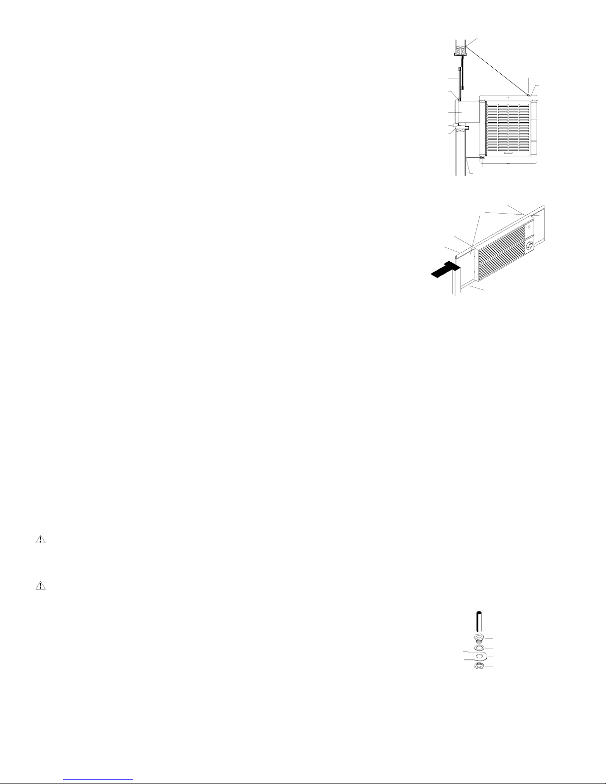
COOLER INSTALLATION
• Install window panel re-
A
tainers. Place two panel
retainer strips onto bottom of neck flange and
position to the width of
the window. Cut the
strips to fit if necessary. These strips
hold the window fillin panels (Fig. 2).
WINDOW
NECK
D
C
H
E
“S” HOOK
B
• Position cooler in
window. Position
neck of cooler so that
bottom of neck flange
rests on window sill
and flange (E-Fig. 1)
WINDOW FILL-
IN PANELS
G
F
FIG. 1
is snug against
edge of sill (H-Fig.
1). With cooler in
position, hook the
TOP PANEL
RETAINER
“S” hooks into the
holes of the top pan
near the back of the
cooler (B-Fig. 1).
BOTTOM PANEL
RETAINER
FIG. 2
• Break fill-in panels to
fit. With cooler installed, as described above, measure for
each window fill-in panel and score with sharp knife and
straight edge guide to desired width. To break window fillin panels, the panel should be laid over the edge of a straight
flat surface at the point to be broken off. Apply pressure on
the edge of the panel that extends over the edge of the
surface and break off unwanted piece.
• Install fill-in panels. Place one window fill-in panel on each
side of grill and into panel retainer strip at bottom of grill.
Place the other panel retainer strips onto top of neck flange
and fill-in panels. Be sure the panels are snug up against
cooler neck.
• Place window behind retainer strip. Raise back of cooler
so that the window (D-Fig. 1) may be brought down behind
top of panel retainer strip (C-Fig. 1).
MOUNTING COOLER
CAUTION: Make sure that the mounting surface
is strong enough to support the operating weight of
the cooler when in use. (For operating weight, see
Specification Table.)
CAUTION: Never plug in cooler until installation is
complete and unit has been tested for rigidity.
• Lift out all removable louvered sides.
• Screw chain hooks into window facing. Position the two
chain hooks above the neck of the cooler a distance equal
to the width of the cooler apart (A-Fig. 1). Hook one hanger
chain in each hook and then an “S” hook in the other end of
each chain. NOTE: Chain hooks supplied with this mounting kit have wood screw threads for wood walls. Concrete,
brick walls or concrete blocks require sufficiently strong wing
nuts or anchors with mating hooks.
2
• Level Cooler. Adjust chains so that cooler is level.
• Adjust house legs. Pull out house legs so that the rubber
bumpers rest against house siding (F-Fig. 1). Tighten screw
in retaining collar. (G-Fig. 1).
CONNECTING WATER
• Install overflow assembly. Re-
move nut and place nipple
through the hole in the pan, with
the rubber washer between the
pan and the head of the drain
nipple (Fig. 3). Screw on nut and
draw up tight against bottom of
pan. Insert overflow pipe in nipple
to retain water. The overflow pipe
may be removed to drain the pan when necessary. A garden hose may be screwed onto the drain nipple to drain
water away from your unit.
OVERFLOW PIPE
NIPPLE
RUBBER WASHER
BOTTOM PAN
NUT
FIG. 3
110528
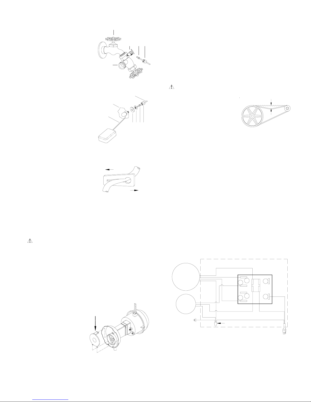
• Connect water supply line.
Install a sillcock and water
valve on faucet as shown by
figure 4. Place the nut and
ferrule on the tubing and
tighten the nut until water
tight.
• Install float valve. Install
valve in the provided hole in
corner post (Fig. 5) and attach water supply line.
• Fill pan. Allow water to
fill to within 1” of top of pan
and adjust float to maintain this water level. This
can be accomplished by
bending the float rod (Fig.
5).
• Adjust water amount.
Your cooler is equipped
with a unique water metering valve (Fig. 6). The
amount of water delivered to
the pads may be decreased by
pressing the plastic valve as
the arrows indicate. If water
is splashing out of water
troughs, you may need to decrease the amount of water
delivery. Check to see that all
pads are saturated with water
and that there are no dry spots
or openings in the pads.
MAINTENANCE
FAUCET
SILLCOCK
CORNER POST
FLOAT ROD
FIG. 4
SUPPLY LINE
FIG. 5
INCREASE
DECREASE
FIG. 6
WATER SUPPLY
VALVE
WATER
WASHER
FERRULE
NUT
NUT
FERRULE
NUT
• Change Pads. Aspen pads should be replaced once or
twice a season, depending upon the length of the season.
At the beginning and at mid season a clean pad is more
absorbent and efficient and will deliver substantially more
cool air.
• Oil bearings. The blower bearings and cooler motor in this
unit should be oiled with a few drops of non-detergent 20/
30 weight oil once each year. The motor does not need oil
if it has no oil lines for oiling. Motors that have no lines are
lifetime oiled at the factory and require no further oiling for
the life of the unit.
CAUTION: Do not over oil. Over oiling can cause mo-
tor burn out, due to excessive oil
getting into motor winding.
• Check belt tension. A 3 lb.
force should deflect the belt 3/
4 inches (see Fig. 8). Readjust belt if needed.
3 LB.
3/4 INCHES
FIG. 8
WINTER SHUT DOWN
• Drain water. Always drain all of the water out of the cooler
and water supply line when not in use for prolonged periods, and particularly at the end of the season. Keep the
water line disconnected from both the unit and water supply so that it does not freeze.
• Cover unit. To protect the life of the finish, a cover for the
unit is suggested in extended periods of non-use.
• Unplug unit from power supply during extended peri-
ods of non-use.
By following the operating, installation, and maintenance suggestions as outlined, you can get many years of efficient and
satisfactory service from your cooler. In the event additional
information is desired, your dealer will be more than glad to
assist you in every possible way.
WARNING: Before doing any maintenance be sure
power is off and unit is unplugged. This is for your safety.
SPRING START-UP
• Clean pump. Cleaning the pump is necessary once a year
at start-up. For your safety, turn unit off and unplug from
power receptacle. Remove the pump from the mount slot.
Remove the base of the pump as shown in Fig. 7. Clean
the pump and turn the impeller to ensure free operation.
Remove the pump spout and check for any blockage. After
cleaning, reinstall the base onto the pump. Reattach the
pump to the mount in
the cooler using the
plastic retainer to ensure that the pump will
not overturn. Do not
forget to replace the
spout and water delivery tube onto the pump
outlet. The pump has
automatic reset thermal
protection.
DEPRESS HERE
TO REMOVE
FIG. 7
BLOWER
MOTOR
PUMP
MOTOR
WIRING DIAGRAM
WHITE-COM
BLACK-HI
4
3
PLAIN
2
1
WIRE CONNECTOR
GREEN
RED-LO
RIBBED-COM
GREEN-GROUND
SWITCH
B
A
RIBBED-COM
PLAIN
110528
3

TROUBLESHOOTING
PROBLEM POSSIBLE CAUSE REMEDY
Failure to start or no
air delivery
Inadequate air
delivery with cooler
running
Inadequate cooling
Motor cycles on and
off
Noisy
1. No electrical power to unit
• Fuse blown
• Circuit breaker tripped
• Electric cord unplugged or damaged
2. Belt too loose or tight
3. Motor overheated
• Belt too tight
• Blower bearings dry
4. Motor locked
1. Insufficient air exhaust
2. Belt too loose
3. Pads plugged
1. Inadequate exhaust in house
2. Pads not wet
• Pads plugged
• Open spots in pads
• Trough holes clogged
• Pump not working properly
1. Low voltage
2. Excessive belt tension
3. Blower shaft tight or locked
4. Bearings dry
1. Bearings dry
2. Wheel rubbing blower housing
3. Loose parts
1. Check power
• Replace fuse
• Reset breaker
• Plug in cords or replace if damaged
2. Adjust belt tension
3. Determine cause of overheating
• Adjust belt tension
• Oil blower bearings
4. Replace motor
1. Open windows or doors to increase air flow
2. Adjust belt tension or replace if needed
3. Replace pads
1. Open windows or doors to increase air flow
2. Check water distribution system
• Replace pads
• Repack pads
• Clean trough and unplug holes
• Replace or clean pump (Unplug unit)
1. Check voltage
2. Adjust belt tension
3. Oil or replace bearings (Unplug unit)
4. Oil bearings
1. Oil bearings
2. Inspect and realign (Unplug unit)
3. Tighten loose parts
Excessive humidity in
house
Musty or unpleasant
odor
Water draining from
cooler
1. Inadequate exhaust
1. Stale or stagnate water in cooler
2. Pads mildewed or clogged
3. Pads not wetting properly
• Trough holes clogged
• Pump not working properly
1. Float arm not adjusted properly
2. Overflow assembly leaking
1. Open doors or windows
1. Drain pan and clean pads
2. Replace pads
3. Check water distribution system
• Clean
• Replace or clean pump (Unplug unit)
1. Adjust float
2. Tighten nut and overflow pipe.
4
110528
 Loading...