

Page 1

Unity Network
®
Interface Device (ID)
Service Manual
2009517-002 Revision A
Page 2

127(Due to continuing product innovation, specifications in this manual are subject to change without
notice.
Listed below are GE Medical Systems Information Technologies trademarks used in this document. All other
trademarks contained herein are the property of their respective owners.
DASH and UNITY NETWORK are trademarks of GE Medical Systems Information Technologies registered
in the United States Patent and Trademark Office.
Unity Network
®
Interface Device (ID) is a trademark of GE Medical Systems Information Technologies.
© GE Medical Systems Information Technologies, 2002. All rights reserved.
T-2 Unity Network ID Connectivity Revision A
2009517-002 20 November 2002
Page 3

Contents
1 Introduction . . . . . . . . . . . . . . . . . . . . . . . . . . . . . . . . . . . . 1-1
Manual Information . . . . . . . . . . . . . . . . . . . . . . . . . . . . . . . . . . . . . . . . . . . . . . . . . . 1-3
Revision History . . . . . . . . . . . . . . . . . . . . . . . . . . . . . . . . . . . . . . . . . . . . . . . . . . .1-3
Manual Purpose . . . . . . . . . . . . . . . . . . . . . . . . . . . . . . . . . . . . . . . . . . . . . . . . . . .1-3
Intended Audience . . . . . . . . . . . . . . . . . . . . . . . . . . . . . . . . . . . . . . . . . . . . . . . . .1-3
Naming Conventions . . . . . . . . . . . . . . . . . . . . . . . . . . . . . . . . . . . . . . . . . . . . . . .1-3
Definitions . . . . . . . . . . . . . . . . . . . . . . . . . . . . . . . . . . . . . . . . . . . . . . . . . . . . . . .1-4
Safety Information . . . . . . . . . . . . . . . . . . . . . . . . . . . . . . . . . . . . . . . . . . . . . . . . . . . 1-5
Responsibility of the Manufacturer . . . . . . . . . . . . . . . . . . . . . . . . . . . . . . . . . . . . .1-5
General . . . . . . . . . . . . . . . . . . . . . . . . . . . . . . . . . . . . . . . . . . . . . . . . . . . . . . . . .1-5
Warnings, Cautions, and Notes . . . . . . . . . . . . . . . . . . . . . . . . . . . . . . . . . . . . . . .1-6
Equipment Symbols . . . . . . . . . . . . . . . . . . . . . . . . . . . . . . . . . . . . . . . . . . . . . . . .1-6
Service Information . . . . . . . . . . . . . . . . . . . . . . . . . . . . . . . . . . . . . . . . . . . . . . . . . . 1-7
Service Requirements . . . . . . . . . . . . . . . . . . . . . . . . . . . . . . . . . . . . . . . . . . . . . .1-7
Equipment Identification . . . . . . . . . . . . . . . . . . . . . . . . . . . . . . . . . . . . . . . . . . . . .1-7
2 Equipment Overview . . . . . . . . . . . . . . . . . . . . . . . . . . . . . 2-1
System Components . . . . . . . . . . . . . . . . . . . . . . . . . . . . . . . . . . . . . . . . . . . . . . . . . 2-3
System Operation . . . . . . . . . . . . . . . . . . . . . . . . . . . . . . . . . . . . . . . . . . . . . . . . .2-3
Unity Network ID Components . . . . . . . . . . . . . . . . . . . . . . . . . . . . . . . . . . . . . . . .2-5
Interface Adapters . . . . . . . . . . . . . . . . . . . . . . . . . . . . . . . . . . . . . . . . . . . . . . . . .2-6
Supported Devices . . . . . . . . . . . . . . . . . . . . . . . . . . . . . . . . . . . . . . . . . . . . . . . . . . 2-7
Anesthesia Machines . . . . . . . . . . . . . . . . . . . . . . . . . . . . . . . . . . . . . . . . . . . . . . .2-8
Continuous Cardiac Output Monitors . . . . . . . . . . . . . . . . . . . . . . . . . . . . . . . . . . .2-9
Gas Analyzers . . . . . . . . . . . . . . . . . . . . . . . . . . . . . . . . . . . . . . . . . . . . . . . . . . . .2-9
Infusion Pumps . . . . . . . . . . . . . . . . . . . . . . . . . . . . . . . . . . . . . . . . . . . . . . . . . .2-10
Patient Monitors . . . . . . . . . . . . . . . . . . . . . . . . . . . . . . . . . . . . . . . . . . . . . . . . . .2-10
Pulse Oximeters . . . . . . . . . . . . . . . . . . . . . . . . . . . . . . . . . . . . . . . . . . . . . . . . . .2-11
Transcutaneous Monitors . . . . . . . . . . . . . . . . . . . . . . . . . . . . . . . . . . . . . . . . . .2-12
Urometers . . . . . . . . . . . . . . . . . . . . . . . . . . . . . . . . . . . . . . . . . . . . . . . . . . . . . .2-12
Ventilators . . . . . . . . . . . . . . . . . . . . . . . . . . . . . . . . . . . . . . . . . . . . . . . . . . . . . .2-12
Technical Specifications . . . . . . . . . . . . . . . . . . . . . . . . . . . . . . . . . . . . . . . . . . . . . 2-15
Performance Specifications . . . . . . . . . . . . . . . . . . . . . . . . . . . . . . . . . . . . . . . . .2-15
Environmental Specifications . . . . . . . . . . . . . . . . . . . . . . . . . . . . . . . . . . . . . . . .2-15
Physical Specifications . . . . . . . . . . . . . . . . . . . . . . . . . . . . . . . . . . . . . . . . . . . .2-15
Certification . . . . . . . . . . . . . . . . . . . . . . . . . . . . . . . . . . . . . . . . . . . . . . . . . . . . .2-16
Classification . . . . . . . . . . . . . . . . . . . . . . . . . . . . . . . . . . . . . . . . . . . . . . . . . . . .2-16
Revision A Unity Network ID Connectivity Device i
2009517-002
Page 4

3 Installation . . . . . . . . . . . . . . . . . . . . . . . . . . . . . . . . . . . . . 3-1
General Information . . . . . . . . . . . . . . . . . . . . . . . . . . . . . . . . . . . . . . . . . . . . . . . . . . 3-3
Installation Procedures . . . . . . . . . . . . . . . . . . . . . . . . . . . . . . . . . . . . . . . . . . . . .3-3
Special Equipment . . . . . . . . . . . . . . . . . . . . . . . . . . . . . . . . . . . . . . . . . . . . . . . . .3-3
Communication Tips . . . . . . . . . . . . . . . . . . . . . . . . . . . . . . . . . . . . . . . . . . . . . . .3-3
Changing Internet Addresses . . . . . . . . . . . . . . . . . . . . . . . . . . . . . . . . . . . . . . . .3-4
Configuration . . . . . . . . . . . . . . . . . . . . . . . . . . . . . . . . . . . . . . . . . . . . . . . . . . . . . . . 3-5
Connections for Stand-Alone Mode of Operation . . . . . . . . . . . . . . . . . . . . . . . . . 3-9
Connections for Peripheral Mode of Operation . . . . . . . . . . . . . . . . . . . . . . . . . . 3-10
Monitor Requirements . . . . . . . . . . . . . . . . . . . . . . . . . . . . . . . . . . . . . . . . . . . . .3-10
Connection to Dash Pro 3000/4000 Monitors . . . . . . . . . . . . . . . . . . . . . . . . . . .3-11
Connection to Solar 8000M/9500 Monitors . . . . . . . . . . . . . . . . . . . . . . . . . . . . .3-12
Peripheral Device Connections . . . . . . . . . . . . . . . . . . . . . . . . . . . . . . . . . . . . . . . 3-14
Completion . . . . . . . . . . . . . . . . . . . . . . . . . . . . . . . . . . . . . . . . . . . . . . . . . . . . . . . . 3-16
4 Maintenance . . . . . . . . . . . . . . . . . . . . . . . . . . . . . . . . . . . 4-1
Maintenance Schedule . . . . . . . . . . . . . . . . . . . . . . . . . . . . . . . . . . . . . . . . . . . . . . . 4-3
Manufacturer Recommendations . . . . . . . . . . . . . . . . . . . . . . . . . . . . . . . . . . . . . .4-3
Visual Inspection . . . . . . . . . . . . . . . . . . . . . . . . . . . . . . . . . . . . . . . . . . . . . . . . . .4-3
Calibration . . . . . . . . . . . . . . . . . . . . . . . . . . . . . . . . . . . . . . . . . . . . . . . . . . . . . . .4-3
Cleaning . . . . . . . . . . . . . . . . . . . . . . . . . . . . . . . . . . . . . . . . . . . . . . . . . . . . . . . . . . . 4-4
Cleaning Precautions . . . . . . . . . . . . . . . . . . . . . . . . . . . . . . . . . . . . . . . . . . . . . . .4-4
Exterior Cleaning . . . . . . . . . . . . . . . . . . . . . . . . . . . . . . . . . . . . . . . . . . . . . . . . . .4-4
Electrical Safety Tests . . . . . . . . . . . . . . . . . . . . . . . . . . . . . . . . . . . . . . . . . . . . . . . . 4-5
General . . . . . . . . . . . . . . . . . . . . . . . . . . . . . . . . . . . . . . . . . . . . . . . . . . . . . . . . .4-5
Recommendations . . . . . . . . . . . . . . . . . . . . . . . . . . . . . . . . . . . . . . . . . . . . . . . . .4-5
Power Outlet Test . . . . . . . . . . . . . . . . . . . . . . . . . . . . . . . . . . . . . . . . . . . . . . . . .4-6
Ground (Earth) Integrity . . . . . . . . . . . . . . . . . . . . . . . . . . . . . . . . . . . . . . . . . . . . .4-6
Ground (Earth) Wire Leakage Current Tests . . . . . . . . . . . . . . . . . . . . . . . . . . . . .4-8
Enclosure Leakage Current Test . . . . . . . . . . . . . . . . . . . . . . . . . . . . . . . . . . . . . .4-9
Test Completion . . . . . . . . . . . . . . . . . . . . . . . . . . . . . . . . . . . . . . . . . . . . . . . . . .4-10
Checkout Procedure . . . . . . . . . . . . . . . . . . . . . . . . . . . . . . . . . . . . . . . . . . . . . . . . 4-11
Test Frequency . . . . . . . . . . . . . . . . . . . . . . . . . . . . . . . . . . . . . . . . . . . . . . . . . .4-11
Special Equipment . . . . . . . . . . . . . . . . . . . . . . . . . . . . . . . . . . . . . . . . . . . . . . . .4-11
Peripheral Device Connectors . . . . . . . . . . . . . . . . . . . . . . . . . . . . . . . . . . . . . . .4-11
Identification . . . . . . . . . . . . . . . . . . . . . . . . . . . . . . . . . . . . . . . . . . . . . . . . . . . . .4-12
Completion . . . . . . . . . . . . . . . . . . . . . . . . . . . . . . . . . . . . . . . . . . . . . . . . . . . . . .4-12
PM Form . . . . . . . . . . . . . . . . . . . . . . . . . . . . . . . . . . . . . . . . . . . . . . . . . . . . . . .4-13
ii Unity Network ID Connectivity Device Revision A
2009517-002
Page 5

Repair Log . . . . . . . . . . . . . . . . . . . . . . . . . . . . . . . . . . . . . . . . . . . . . . . . . . . . . . . . 4-14
5 Troubleshooting . . . . . . . . . . . . . . . . . . . . . . . . . . . . . . . . 5-1
General Fault Isolation . . . . . . . . . . . . . . . . . . . . . . . . . . . . . . . . . . . . . . . . . . . . . . . 5-3
Initial Considerations . . . . . . . . . . . . . . . . . . . . . . . . . . . . . . . . . . . . . . . . . . . . . . .5-3
PC Communication Problems . . . . . . . . . . . . . . . . . . . . . . . . . . . . . . . . . . . . . . . .5-3
Software Compatibility . . . . . . . . . . . . . . . . . . . . . . . . . . . . . . . . . . . . . . . . . . . . . .5-3
Serviceability . . . . . . . . . . . . . . . . . . . . . . . . . . . . . . . . . . . . . . . . . . . . . . . . . . . . .5-3
Notification of Equipment Upgrade . . . . . . . . . . . . . . . . . . . . . . . . . . . . . . . . . . . . . 5-4
Software Compatibility . . . . . . . . . . . . . . . . . . . . . . . . . . . . . . . . . . . . . . . . . . . . . .5-4
Visual Inspection . . . . . . . . . . . . . . . . . . . . . . . . . . . . . . . . . . . . . . . . . . . . . . . . . . . . 5-5
AC Line Voltage Test . . . . . . . . . . . . . . . . . . . . . . . . . . . . . . . . . . . . . . . . . . . . . . . . . 5-6
120 VAC, 50/60 Hz . . . . . . . . . . . . . . . . . . . . . . . . . . . . . . . . . . . . . . . . . . . . . . . .5-6
240 VAC, 50/60 Hz . . . . . . . . . . . . . . . . . . . . . . . . . . . . . . . . . . . . . . . . . . . . . . . .5-6
Problems and Solutions . . . . . . . . . . . . . . . . . . . . . . . . . . . . . . . . . . . . . . . . . . . . . . 5-7
Status LED Displays . . . . . . . . . . . . . . . . . . . . . . . . . . . . . . . . . . . . . . . . . . . . . . . . . 5-9
System Status . . . . . . . . . . . . . . . . . . . . . . . . . . . . . . . . . . . . . . . . . . . . . . . . . . . .5-9
Peripheral Device Connection Status . . . . . . . . . . . . . . . . . . . . . . . . . . . . . . . . .5-10
6 Technical Replacement Units . . . . . . . . . . . . . . . . . . . . . 6-1
Ordering Parts . . . . . . . . . . . . . . . . . . . . . . . . . . . . . . . . . . . . . . . . . . . . . . . . . . . . . . 6-3
Technical Replacement Units . . . . . . . . . . . . . . . . . . . . . . . . . . . . . . . . . . . . . . . . . . 6-3
Part Replacement Procedures . . . . . . . . . . . . . . . . . . . . . . . . . . . . . . . . . . . . . . . . . 6-4
Cover Replacement . . . . . . . . . . . . . . . . . . . . . . . . . . . . . . . . . . . . . . . . . . . . . . . .6-4
PCB Replacement . . . . . . . . . . . . . . . . . . . . . . . . . . . . . . . . . . . . . . . . . . . . . . . . .6-6
Shipping Instructions . . . . . . . . . . . . . . . . . . . . . . . . . . . . . . . . . . . . . . . . . . . . . . . . 6-9
7 Technical Information . . . . . . . . . . . . . . . . . . . . . . . . . . . . 7-1
Theory of Operation . . . . . . . . . . . . . . . . . . . . . . . . . . . . . . . . . . . . . . . . . . . . . . . . . . 7-3
Microprocessor . . . . . . . . . . . . . . . . . . . . . . . . . . . . . . . . . . . . . . . . . . . . . . . . . . .7-4
Peripherals . . . . . . . . . . . . . . . . . . . . . . . . . . . . . . . . . . . . . . . . . . . . . . . . . . . . . . .7-5
Communication Interface . . . . . . . . . . . . . . . . . . . . . . . . . . . . . . . . . . . . . . . . . . . .7-6
Ethernet Communication . . . . . . . . . . . . . . . . . . . . . . . . . . . . . . . . . . . . . . . . . . . .7-7
Power Supply Conversion . . . . . . . . . . . . . . . . . . . . . . . . . . . . . . . . . . . . . . . . . . .7-8
ESD Protection . . . . . . . . . . . . . . . . . . . . . . . . . . . . . . . . . . . . . . . . . . . . . . . . . . .7-8
Revision A Unity Network ID Connectivity Device iii
2009517-002
Page 6

Input and Output Connectors . . . . . . . . . . . . . . . . . . . . . . . . . . . . . . . . . . . . . . . . . . 7-9
Ports 1 – 8 . . . . . . . . . . . . . . . . . . . . . . . . . . . . . . . . . . . . . . . . . . . . . . . . . . . . . . .7-9
Ethernet Port . . . . . . . . . . . . . . . . . . . . . . . . . . . . . . . . . . . . . . . . . . . . . . . . . . . . .7-9
RS 232 Service Connector . . . . . . . . . . . . . . . . . . . . . . . . . . . . . . . . . . . . . . . . .7-10
HyperTerminal . . . . . . . . . . . . . . . . . . . . . . . . . . . . . . . . . . . . . . . . . . . . . . . . . . . . . 7-11
Special Equipment . . . . . . . . . . . . . . . . . . . . . . . . . . . . . . . . . . . . . . . . . . . . . . . .7-11
Connections . . . . . . . . . . . . . . . . . . . . . . . . . . . . . . . . . . . . . . . . . . . . . . . . . . . . .7-11
Using HyperTerminal . . . . . . . . . . . . . . . . . . . . . . . . . . . . . . . . . . . . . . . . . . . . . .7-12
Boot Service Menu . . . . . . . . . . . . . . . . . . . . . . . . . . . . . . . . . . . . . . . . . . . . . . . . . 7-13
Using the Boot Service Menu . . . . . . . . . . . . . . . . . . . . . . . . . . . . . . . . . . . . . . .7-13
Service Menu . . . . . . . . . . . . . . . . . . . . . . . . . . . . . . . . . . . . . . . . . . . . . . . . . . . . . . 7-15
Using the Service Menu . . . . . . . . . . . . . . . . . . . . . . . . . . . . . . . . . . . . . . . . . . . .7-15
Error and Event Log Menus . . . . . . . . . . . . . . . . . . . . . . . . . . . . . . . . . . . . . . . . .7-16
Exploded View . . . . . . . . . . . . . . . . . . . . . . . . . . . . . . . . . . . . . . . . . . . . . . . . . . . . . 7-18
iv Unity Network ID Connectivity Device Revision A
2009517-002
Page 7

1 Introduction
Revision A Unity Network ID Connectivity Device 1-1
2009517-002
Page 8

For your notes
1-2 Unity Network ID Connectivity Device Revision A
2009517-002
Page 9

Manual Informatio n
Revision History
Each page of this document has the document part number and revision
letter at the bottom of the page. The revision letter changes whenever
the document is updated.
Manual Purpose
This manual supplies technical information for service representatives
and technical personnel so they can maintain the equipment to the
assembly level. Use it as a guide for maintenance and electrical repairs
considered technician repairable. Whe re necess ary the manua l identifie s
additional sources of relevant information and technical assistance.
Introduction: Manual Information
Revision Date Comment
A 20 November 2002 Initial release.
Intended Audience
Naming Conventions
See the operator’s manual for the instructions necessary to operate the
equipment safely in accordance with its function and intended use.
This manual is intended for service representatives and technical
personnel who maintain, troubleshoot, or repair this equipment.
In this manual, the Unity Network Interface Device (ID) is referred to as
the Unity Network ID connectivity device.
Revision A Unity Network ID Connectivity Device 1-3
2009517-002
Page 10

Definitions
Introduction: Manual Information
Black text Indicates keys on the keyboard, text to be entered, or h ardware items
such as buttons or switches on the equipment.
Italicized text Indicates software terms that identify menu items, buttons, or options
in various windows.
Ctrl+Esc Indicates a keyboard operation. A (+) sign between the names of two
keys indicates that you must press and hold the first key while
pressing the second key once.
For example, “Press Ctrl+Esc” means to press and hold down the
Ctrl key while pressing the Esc key.
<Space> Indicates you must press the spacebar. When instructions are given
for typing a precise text string with one or more spaces, the point
where the spacebar must be pressed is indicated as: <Space>. The
purpose of the < > brackets is to ensure you press the spacebar
when required.
Enter Indicates you must press the “Enter” or “Return” key on the
keyboard. Do not type “enter”.
1-4 Unity Network ID Connectivity Device Revision A
2009517-002
Page 11

Introduction: Safety Information
Safety Information
Responsibility of the Manuf acturer
GE Medical Systems Information Technologies is responsible for the
effects of safety, reliability, and performance only if:
n
assembly operations, extensions, readjustments, modifications, or
repairs are carrie d out by persons aut horized b y GE Medica l Systems
Information Technologies, Inc.;
n
the electrical installation of the relevant room complies with the
requirements of the appropriate regulations; and
n
the device is used in accordance with the instructions for use.
General
This device is intended for use under the direct supervision of a licensed
health care practitioner.
This device is not intended for home use.
Federal law restricts this device to be sold by or on the order of a
physician.
Contact GE Medical Systems Information Technologies before connecting
any devices or versions of devices not recommended in this manual to the
connectivity device.
Parts and accessories used must meet t he requireme nts of t he appli cable
IEC 60601 series sa fety st andard s, and/ or t he sy stem co nfigura tion mus t
meet the requirements of the IEC 60601-1-1 medical electrical systems
standard.
Periodically, and whenever the integrity of the device is in doubt, test all
functions.
The use of ACCESSORY equipment not complying with the equivalent
safety requirements of this equipment may lead to a reduced level of
safety of the resulting system. Consideration relating to the choice shall
include:
n
use of the accessory in the PATIENT VICINITY; and
n
evidence that the safety certification of the ACCESSORY has been
performed in accordance to the appropriate IEC 60601-1 and/or IEC
60601-1-1 harmonized national standard.
If the installation of the equipment, in the USA, will use 240V rather
than 120V, the source must be a center-tapped, 240V, single-phase
circuit.
Revision A Unity Network ID Connectivity Device 1-5
2009517-002
Page 12
Introduction: Safety Information
001
002
003
4P41
004
Warnings, Cautions, and Notes
The terms danger, warning, and caution are used throughout this
manual to point out hazards and to designate a degree or level of
seriousness. Familiarize yourself with their definitions and significance.
Hazard is defined as a source of potential injury to a person.
DANGER indicates an imminent hazard which, if not avoided, will
result in death or serious injury.
WARNING indicates a potential hazard or unsafe practice which, if not
avoided, could result in death or serious injury.
CAUTION indicates a potential hazard or unsafe practice which, if not
avoided, could result in minor personal injury or product/property
damage.
NOTE provides application tips or other useful information to assure
that you get the most from your equipment.
Equipment Symbols
The following symbols appear on the equipment.
ATTENTION: Consult accompanying documents before using the
equipment.
Equipotentiality
Power:
l = ON; O = OFF
Medical Equipment
With respect to electric shock, fire and mechanical hazards only in
accordance with UL 2601-1, and CAN/CSA C22.2 NO. 601.1.
1-6 Unity Network ID Connectivity Device Revision A
2009517-002
Page 13
Service Information
Service Requirements
n
n
n
n
n
Introduction: Service Information
Refer equipment servicing to GE Medical Systems Information
Technologies authorized service personnel only.
Any unauthorized attempt to repair equipment under warr anty voids
that warranty.
It is the user’s responsibility to report the need for service to GE
Medical Systems Information Technologies or to one of it s au thor ized
agents.
Failure on the part of the responsible individual, hospital, or
institution using this equipment to implement a satisfactory
maintenance schedule may cause undue equipment failure and
possible health hazards.
Regular maintenance, irrespective of usage, is essential to ensure
that the equipment will always be functional when required.
Equipment Identification
Every GE Medical Systems Information Technologies device has a
unique serial number for identification. The serial number appears on
the product label of each unit.
D 0 XX 0005 G XX
Month
Manufactured
A = January
B = February
C = March
D = April
E = May
F = June
G = July
H = August
J = September
K = October
L = November
M = December
Year
Manufactured
0 = 2000
1 = 2001
2 = 2002
(and so on)
Product Code
Two-character
product descriptor
Product Sequence
Number
Manufacturing
number (of total units
manufactured)
Division
F = Cardiology
G = Monitoring
N = Freiburg
Hellige
Device Characteristics
One or 2 letters that further
describe the unit, for example:
P = prototype not conforming to
marketing specification
R = refurbished equipment
S = special product
documented under Specials
part numbers
U = upgraded unit
Revision A Unity Network ID Connectivity Device 1-7
2009517-002
Page 14

For your notes
Introduction: Service Information
1-8 Unity Network ID Connectivity Device Revision A
2009517-002
Page 15

2 Equipment Overview
Revision A Unity Network ID Connectivity Device 2-1
2009517-002
Page 16

For your notes
2-2 Unity Network ID Connectivity Device Revision A
2009517-002
Page 17
Equipment Overview: System Components
System Components
System Operation
The Unity Network ID connectivity device acquires digital data from up
to eight peripheral devices, processes this data, and transmits the
formatted data to the monitoring network. The data can then be
displayed on a clinical information system, central station, and/or GE
Medical Systems Information Technologies patient monit or.
127(
Contact your GE Medical Systems Information Technologies
representative for information about the monitors and software
versions that are capable of receiving and displaying information
from a Unity Network ID connectivity device.
Peripheral devices include anesthesia machines, continuous cardiac
output monitors, gas analyzers, IV pumps, patient monitors, pulse
oximeters, transcutaneous monitors, urometers, and ventilators.
Stand-Alone Mode
The Unity Network ID connectivity device operates in either a standalone mode or a peripheral mode of operation.
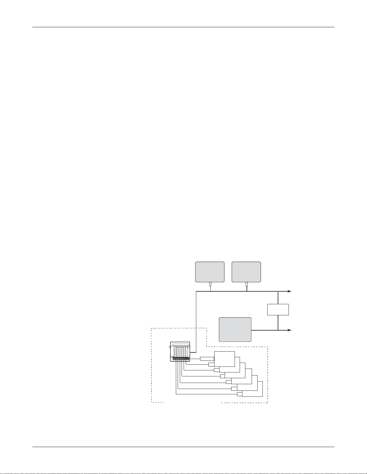
In the stand-alone mode, the Unity Network ID connectivity device
provides data via the Unity Net work to one or more Unity Network
devices capable of viewing remote patient data.
Unity Network ID
Interface Device
Central
Station
Unity Monitoring Network
Peripheral
Adapter
Bedside
Devices
Patient
Monitor
Clinical
Information
System
To Other
Unity Network
Devices
Network
Gateway
To Clinical
Information
System
Network
PATIENT’S ROOM
005
The diagram is an example of patient data flow from peripheral devices
to a clinical information system:
Revision A Unity Network ID Connectivity Device 2-3
2009517-002
Page 18
Peripheral Mode
Equipment Overview: System Components
n
Each peripheral device requires a unique interface adapter to obtain
the patient data.
n
Each adapter is connected by cabling to one of the eight peripheral
device connectors on the Unity Network ID connectivity device.
n
The monitoring network delivers the patient data to a network
gateway that segregates the monitoring network from the clinical
information system. The gateway separates the real-time network
and the transaction-oriented network to assure reliable delivery of
real-time data.
n
The gateway sends the patient data to a clinical information system
or other parts of the hospital’s enterprise-wide network.
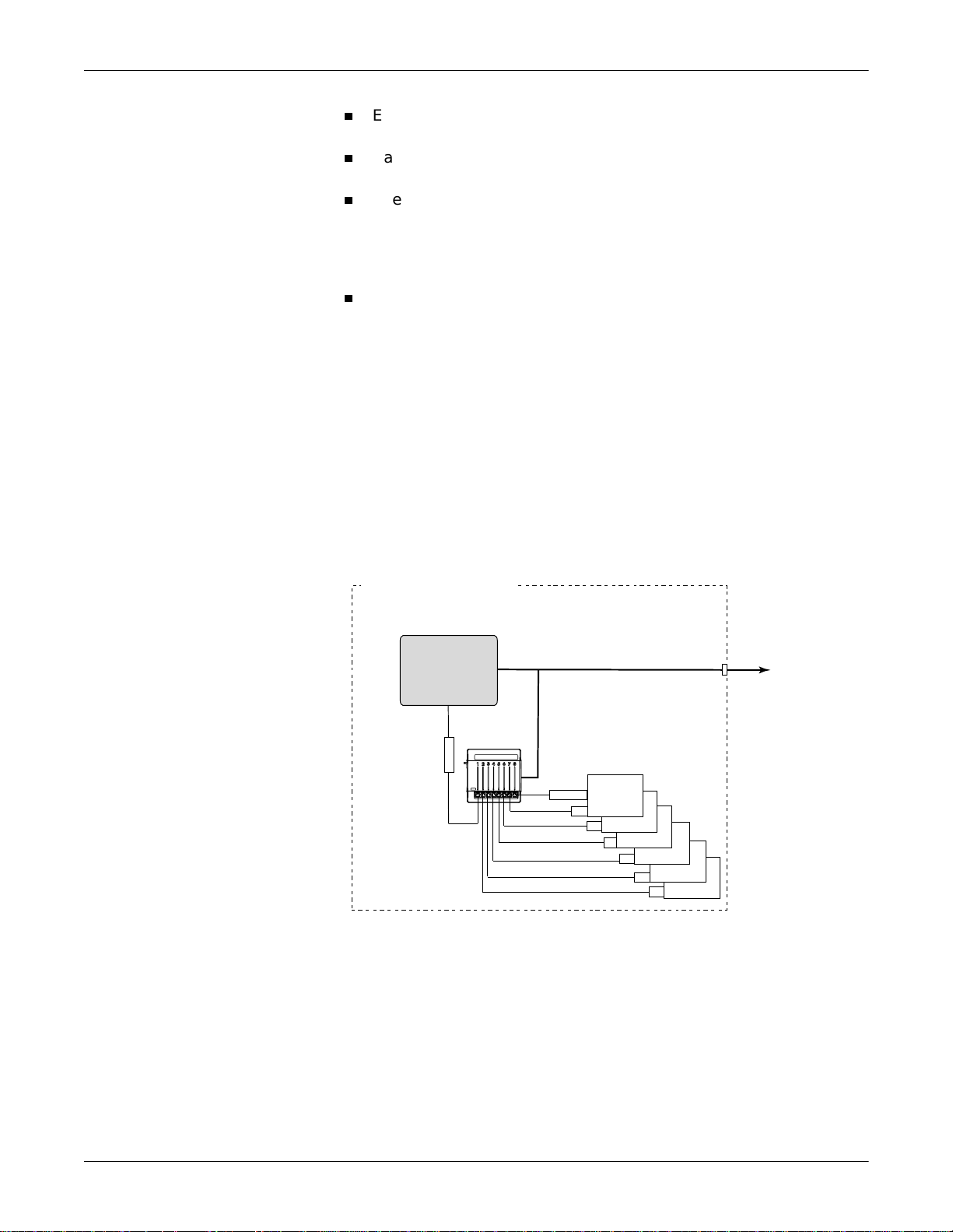
In the peripheral mode, the Unity Network ID connectivity device
provides its collected data to only one Unity Network device, such as a
GE patient monitor. While in this mode, other viewing devices on the
Unity Network cannot view data collected by the Unity Network ID
connectivity device. This mode of operation allows for data collected by
non-GE Medical Systems Information Technologies equipment to be
merged with data collected locally by a GE patient monitor.
Peripheral Mode Operation Using Dash Pro Patient Monitor
PATIENTíSROOM
DashPro
PatientMonitor
UnityNetworkID
InterfaceDevice
Adapter
UnityMonitoringNetwork
Peripheral
Adapter
Bedside
Devices
UnityNetwork
ToOther
Devices
006
2-4 Unity Network ID Connectivity Device Revision A
2009517-002
Page 19
Equipment Overview: System Components
Peripheral Mode Operation Using Solar 8000M/9500 Monitor
PATIENTíSROOM
Solar8000M/9500
Monitor
M-PortNetwork
Unity Network ID Components
UnityNetworkID
InterfaceDevice
UnityMonitoringNetwork
Peripheral
Adapter
Bedside
Devices
ToOther
UnityNetwork
Devices
034
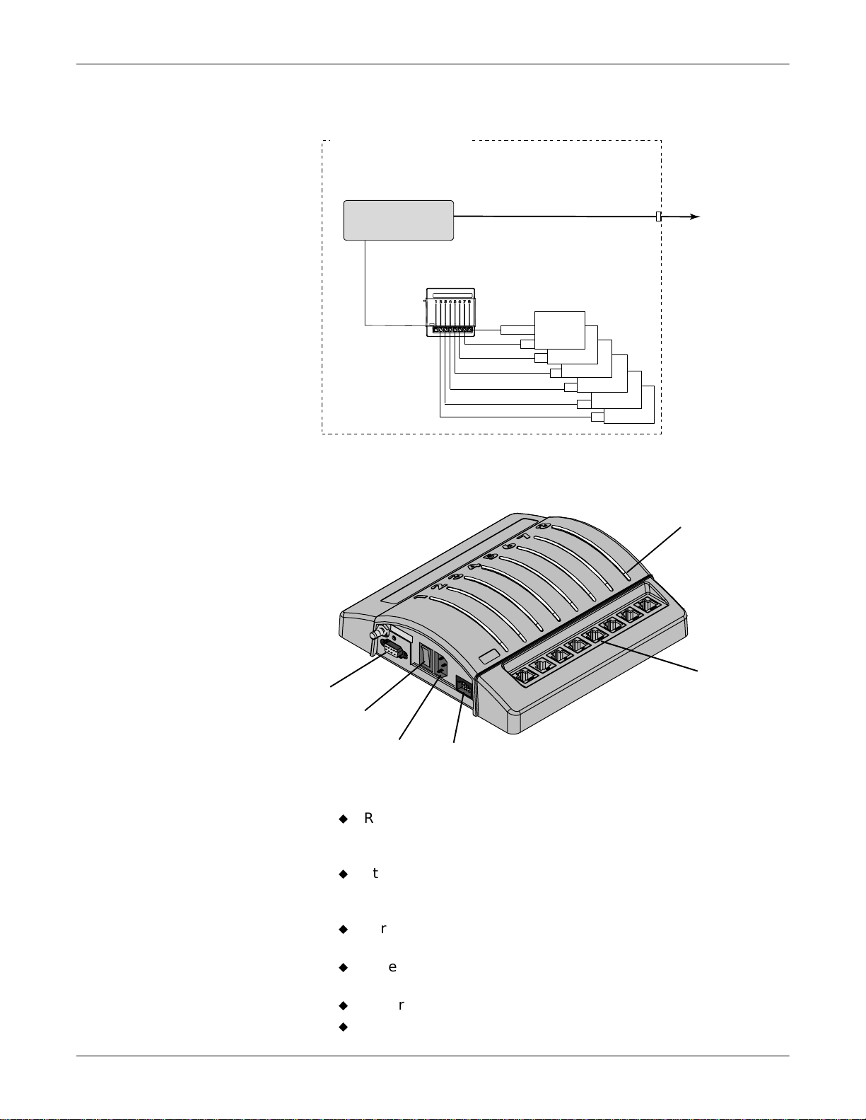
Status LEDs
RS 232
Service
Connector
Power Switch
Power Connector
The Unity Network ID connectivity device components include:
I
0
Peripheral
Device
Connectors
Ethernet
Connector
u
RS 232 Service Connector—A dedicated serial port to
communicate with a personal computer or terminal for
configuration and programming.
u
Status LEDs— Eight bi-color light-emitting-diodes that indicate
proper system function, peripheral device compatibility
problems, and communication errors or delays.
u
Peripheral Device Connectors—Communication ports for eight
peripher al de v ic e s.
u
Ethernet Connector—A single communication port for the
monitoring network.
u
Power Connector—A receptacle for the AC power cord.
u
Power Switch—Power on/off switch with indicator light.
007
Revision A Unity Network ID Connectivity Device 2-5
2009517-002
Page 20
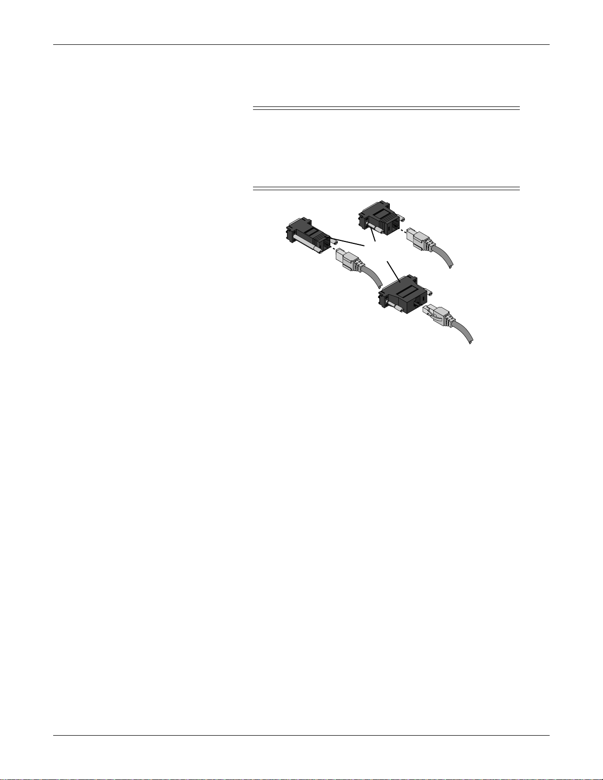
Interface Adapters
Equipment Overview: System Components
&$87,21
Use of the wrong interface a d apter may cause improper
operation of the supported peripheral device. Verify that
the interface adapter on th e peripheral device is the
correct adapter and is operational before the device is
used on a patient.
Interface
Adapters
008
Peripheral devices not manufactured by GE Medical Systems
Information Technologies require a special interface adapter for
connection to the Unity Network ID connectivity device. Dash Pro 3000/
4000 monitors require a special interconnect cable with integral interface
adapter. Interface adapters are available with different connector pin
configurations and are specifically programmed to allow communication
between the specific peripheral device and the Unity Network ID
connectivity device.
127(
Solar 8000M/9000 monitors do not require the use of interface
adapters for connection to the Unity Network ID connectivity de vice.
These monitors utilize a direct Ethernet connection. Refer to the
Installation chapter of this manual for further information.
127(
If your peripheral device software is updated, please complete and
fax the software upgrade notification page found in this manual.
2-6 Unity Network ID Connectivity Device Revision A
2009517-002
Page 21

Supported Devices
This section provides the li st of supported peripheral devices compatible
with the Unity Network ID connectivity device. The devi ces are
organized by type, and part numbers for the corresponding interface
adapter are provided.
127(
Equipment Overview: Supported Devices
Due to continuous product innovation, this list may no longer be
comprehensive. If necessary, call your sales representative for a
current list of supported peripheral devices.
Refer to the host monitor operator documentation for further
information about supported devices and monitored parameters.
Revision A Unity Network ID Connectivity Device 2-7
2009517-002
Page 22

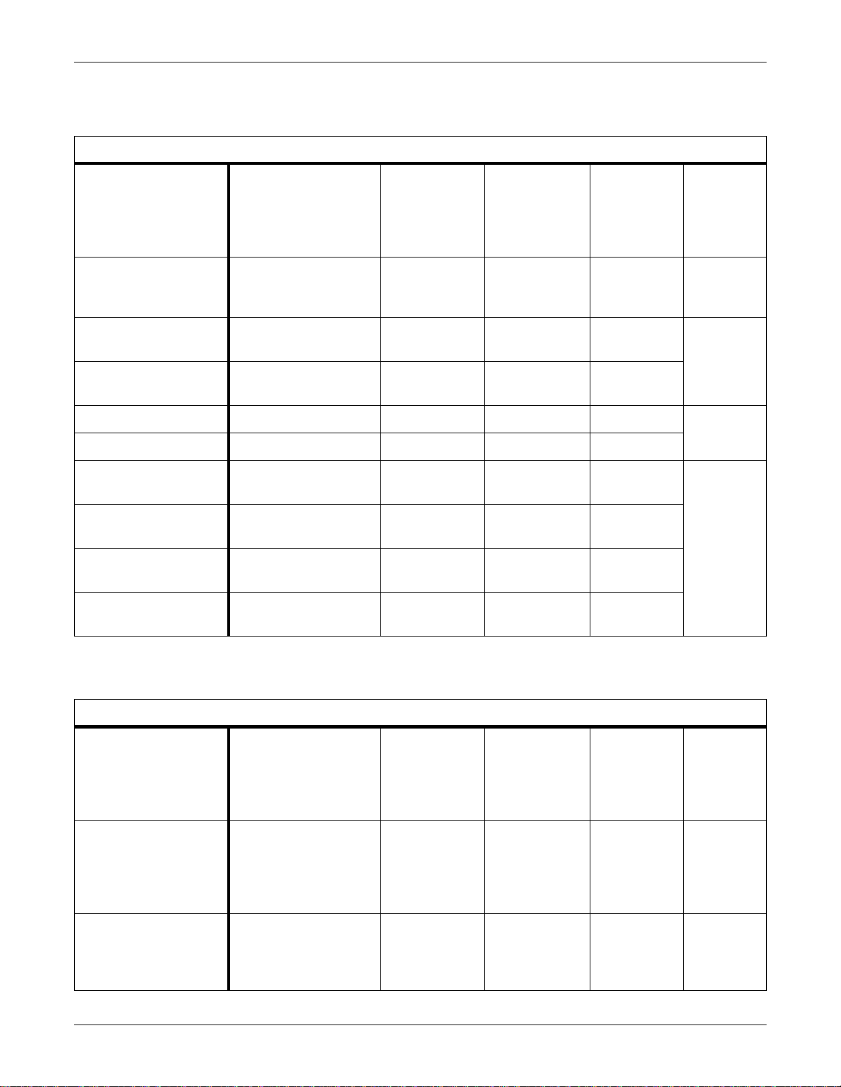
Anesthesia Machines
Equipment Overview: Supported Devices
Supported Anesthesia Machines
Supported Device
North American Dräger
Medical Narkomed 2B
Anesthesia Workstation
North American Dräger
Medical Narkomed 2C
Anesthesia Workstation
North American Dräger
Medical Narkomed 2C
(with CO2+Gas)
Anesthesia Workstation
North American Dräger
Medical Narkomed 3
Anesthesia Workstation
North American Dräger
Medical Narkomed 4
Anesthesia Workstation
Supported Device
Software Version(s)
Narkomed 2B: 2.06
Narkomed 2C: 1.11E
Narkomed 3:
CO2/Agt: 1.02,
O2 Med: 1.04,
Oximeter: 1.07,
Spiromed: 1.04,
Sphymomed: 2.05,
Baromed: 1.06,
CCC: 1.01,
ECC: 1.04,
Alarms CRT: 2.02
Narkomed 4: 1.25
Comm hub: 2.01
Vitalert 2000: 2.05
Vitalert 3200: 1.08
Minimum
Unity Network
Waveform Parameter
— VNT V1A 420915-016
VNT Flow,
VNT Pres
VNT Flow,
VNT Pres,
CO2 Exp
CO2 Exp VNT, Gas, CO2 V1A
VNT Flow,
VNT Pres,
CO2 Exp
VNT V1A
VNT, Gas, CO2 V1A
VNT, Gas, CO2 V1A
ID Software
For This
Interface
Part Number
For
Interface
Adapter
Dräger Medical Cato
Anesthesia Machine
Dräger Medical PM8050
Anesthesia Machine
Dräger Medical Cicero
PM8060 Anesthesia
Machine
(25 Pin)
Dräger Medical Cicero
PM8060 Anesthesia
Machine (9 Pin)
Dräger Medical Julian
Anesthesia Machine
Dräger Medical Cicero EM
Anesthesia Machine
(25 Pin)
Dräger Medical Cicero EM
Anesthesia Machine (9 Pin)
Dräger Medibus Version
3.00 and Device Version
2.02
Dräger Medibus Version
3.00 and Device Version
2.00
Dräger Medibus Version
3.00 and Device Version
2.00
Dräger Medibus Version
3.00 and Device Version
1.00
Dräger Medibus Version
3.00 and Device Version
2.00
Dräger Medibus Version
3.00 and Device Version
2.00
VNT Pres,
CO2 Exp
VNT Pres,
CO2 Exp
VNT Pres,
CO2 Exp
VNT Pres,
CO2 Exp
VNT Pres,
CO2 Exp
VNT Pres,
CO2 Exp
VNT, Gas, CO2 V1A 420915-021
VNT, Gas, CO2 V1A 420915-036
VNT, Gas, CO2 V1A 420915-051
VNT, Gas, CO2 V1A 420915-038
VNT, Gas, CO2 V1A 420915-039
VNT, Gas, CO2 V1A 420915-044
2-8 Unity Network ID Connectivity Device Revision A
2009517-002
Page 23

Equipment Overview: Supported Devices
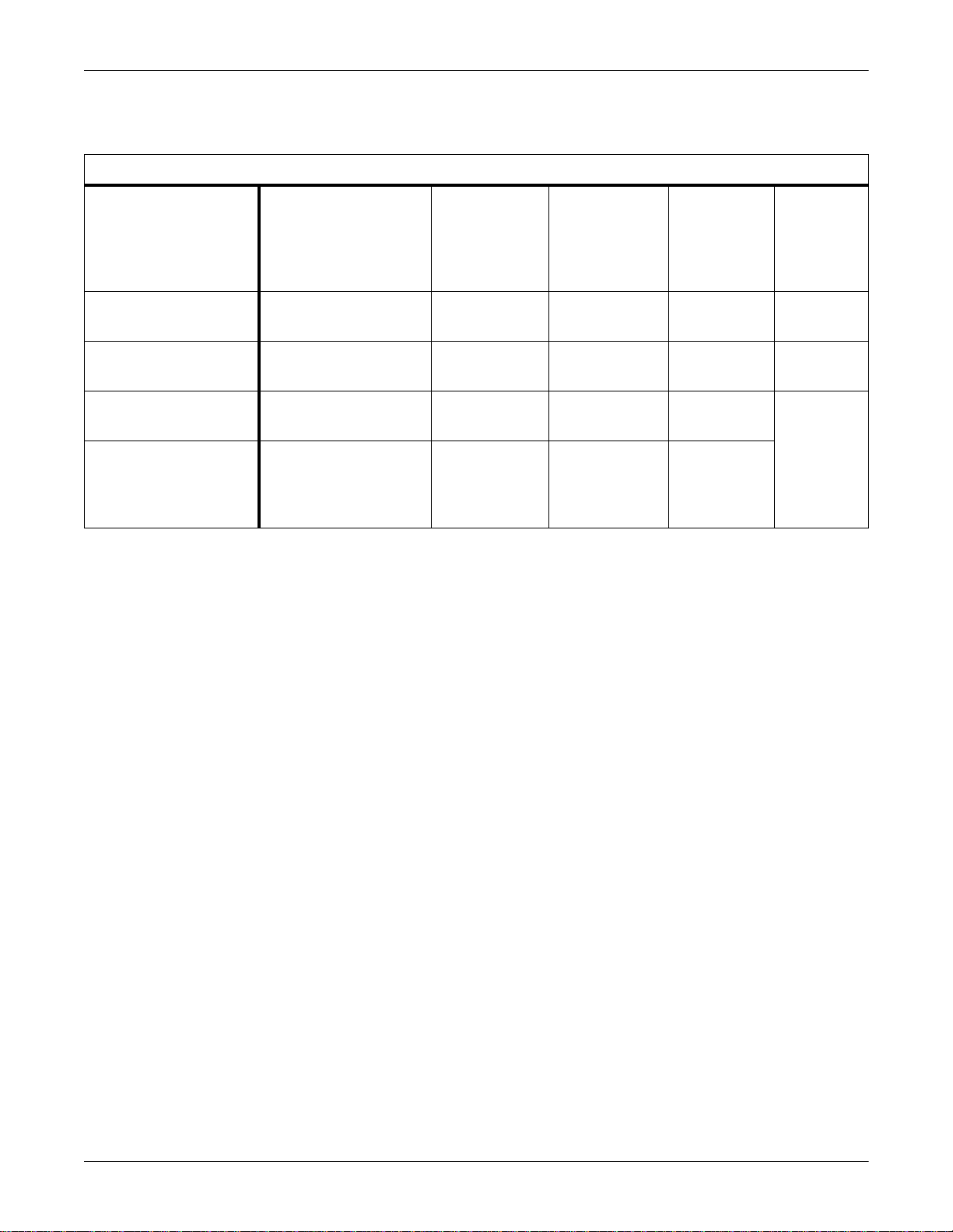
Continuous Cardiac Output Monitors
Supported Continuous Cardiac Output Monitors
Supported Device
Baxter Edwards
Vigilance CCO Monitor
Baxter Edwards Vigilance
CCO Monitor (European)
Abbott Laboratories Q-Vue
Monitor
Abbott Laboratories Q2
Monitor
Gas Analyzers
Minimum
Supported Device
Software Version(s)
Device v4.42, v5.02, v5.3 — CCO, SVO2 V1A 420915- 024
Device v4.42, v5.02, v5.3 — CCO, SVO2 V1A 420915-052
Q-Vue CCO Computer:
Version 1.08, Application
Version 1.08, and BIOS
Version 1.03
Q2 Computer:
Version 3.00, Application
Version 3.00, and BIOS
Version 1.07
Waveform Parameter
— CCO V1A 420915-025
— CCO, SVO2 V1A
Unity Network
ID Software
For This
Interface
Part Number
For
Interface
Adapter
Supported Device
Datex Capnomac Ultima
Gas Analyzer
Datex Ohmeda Rascal II
Anesthetic Gas Analyzer
Datex Ohmeda 5250 RGM
(Respiratory Gas Monitor)
Nellcor Puritan Bennett
N-1000 Pulse Oximeter
Nellcor Puritan Bennett
N-2500 Pulse Oximeter
(N-1000 and N-1500
combined)
Supported Gas Analyzers
Minimum
Supported Device
Software Version(s)
882916-2.0
882916-3.1
1.11 & 1.23 — Gas, CO2 V1A 420915-014
Display: 5.1 & 6.0
Signal: 5.007 & 6.007
ACX: 1.2
Display 2.03.03 (or 2.3) — Gas, CO2,
N-1000 Display: 2.03.03
(or 2.3)
N-1500: 1.02.03 (or 1.2)
Waveform Parameter
— Gas, CO2 V1A 420915- 004
— Gas, CO2 V1A 420915-015
SPO2x
— Gas, CO2,
SPO2x
Unity Network
ID Software
For This
Interface
V1A 420915-034
V1A
Part Number
For
Interface
Adapter
Revision A Unity Network ID Connectivity Device 2-9
2009517-002
Page 24
Infusion Pumps
Equipment Overview: Supported Devices
Supported Infusion Pumps
Minimum
Supported Device
Abbott Laboratories
LifeCare 5000 Concurrent
Flow Infusion System
Baxter Flo-Gard 6201
IV Pump
Baxter Flo-Gard 6301
IV Pump
Alaris Medical IVAC 560 0.21 — IV V1A 418265-028
Alaris Medical IVAC 570 0.09 IV V1A
Alaris Medical IMED
Gemini PC-1 IV Pump
Alaris Medical IMED
Gemini PC-2 IV Pump
Alaris Medical IMED
Gemini PC-2TX IV Pump
Supported Device
Software Version(s)
1.6 — IV V1A 418265-026
1.04–1.13 — IV V1A 418265-027
1.08–1.11 — IV V1A
7.11 — IV V1A 418265-029
2.49a — IV V1A
2.31 — IV V1A
Waveform Parameter
Unity Network
ID Software
For This
Interface
Part Number
For
Interface
Adapter
Alaris Medical IMED
Gemini PC-4 IV Pump
Patient Monitors
Supported Device
Hellige SMU EVO Patient
Monitor
Siemens SC9000 Patient
Monitor
1.31 — IV V1A
Supported Patient Monitors
Minimum
Supported Device
Software Version(s)
8.0E — Gas, CO2,
None Specified — CO2, SPO2x,
Waveform Parameter
SpO2x, TCO2,
TCx, ECGx, RRx,
NBPx, BPx,
TMPx, BTCOx
ECGx, RRx,
NBPx, BPx,
TMPx, BTCOx
Unity Network
ID Software
For This
Interface
V1A 420915- 032
V1A 420915-035
Part Number
For
Interface
Adapter
2-10 Unity Network ID Connectivity Device Revision A
2009517-002
Page 25
Pulse Oximeters
Equipment Overview: Supported Devices
Supported Pulse Oximeters
Supported Device
Nellcor Puritan Bennett
N-200 Pulse Oximeter
Nellcor Puritan Bennett
N-395 Pulse Oximeter
Nellcor Puritan Bennett
N-1000 Pulse Oximeter
Nellcor Puritan Bennett
N-2500 Pulse Oximeter
(N-1000 and N-1500
combined)
Supported Device
Software Version(s)
Monitor Version 2.9
Powerbase Version 2.73
1.7.0.0, 1.8.0.0, 1.9.0.2,
1.9.3.0
Display 2.03.03 (or 2.3) — Gas, CO2,
N-1000 Display: 2.03.03
(or 2.3)
N-1500: 1.02.03 (or 1.2)
Waveform Parameter
— SPO2x V1A 420915- 033
— SPO2x V1A 420915-069
SPO2x
— Gas, CO2,
SPO2x
Minimum
Unity Network
ID Software
For This
Interface
V1A 420915-034
V1A
Part Number
For
Interface
Adapter
Revision A Unity Network ID Connectivity Device 2-11
2009517-002
Page 26
Equipment Overview: Supported Devices
Transcutaneous Monitors
Supported Transcutaneous Monitors
Supported Device
Novametrix Medical
840/860 TCO2M Monitors
Radiometer Medical TINA
(TCM3) TCO2 Monitor
Urometers
Supported Device
Bard CritiCore 210/220
Urimeters
Minimum
Supported Device
Software Version(s)
3.3
TCO2M: eng-860-14
22 — TCO2 V1A 420915-023
Supported Urometers
Supported Device
Software Version(s)
Any — UO V1A 420915- 030
Waveform Parameter
— TCO2 V1A 420915- 022
Waveform Parameter
Unity Network
ID Software
For This
Interface
Minimum
Unity Network
ID Software
For This
Interface
Part Number
For
Interface
Adapter
Part Number
For
Interface
Adapter
Ventilators
Supported Device
Nellcor Puritan Bennett PB
840 Ventilator
Nellcor Puritan Bennett
7200 A/E/AE/SPE Adult
Ventilators
Supported Ventilators
Minimum
Supported Device
Software Version(s)
4-070212-85-F (English) — VNT V1A 420915-063
26300-85-J (English)
24300-85-F (English)
26300-85-N (English)
26321-85-J (Spanish)
26322-85-E (French)
26323-85-G (German)
26324-85-K (Italian)
Waveform Parameter
— VNT V1A 420915- 001
Unity Network
ID Software
For This
Interface
Part Number
For
Interface
Adapter
2-12 Unity Network ID Connectivity Device Revision A
2009517-002
Page 27

Equipment Overview: Supported Devices
Supported Ventilators
Nellcor Puritan Bennett
Infant Star Neonatal
Ventilator
Nellcor Puritan Bennett
Infant Star 500 Neonatal
Ventilator
Nellcor Puritan Bennett
Infant Star 950 Neonatal
Ventilator
Nellcor Puritan Bennett
Adult Star, Adult Star 1500,
and Adult Star 2000
Ventilators
Siemens Medical Servo
Ventilator (SV) 300
Siemens Medical Servo
Ventilator (SV) 900 C/D/E
Bear Medical Bear 1000
Ventilator
Hamilton Medical Veolar
Ventilator
46 — VNT V1A 420915-008
49 and 107 — VNT V1A
107 — VNT V1A
216 and 218 — VNT V1A 420915-009
COM-PROM V2.0
COM-PROM V2.01
1.0 and 2.0 of Servo
VNT Flow,
VNT V1A 420915-011
VNT Pres
— VNT V1A 420915-002
Computer Module 990
9.7 and A3.3 VNT Flow,
VNT V1A 420915-005
VNT Pres
E V31E.4 N31D.2 R030.0 VNT Flow,
VNT V1A 420915-007
VNT Pres
Hamilton Medical Amadeus
Ventilator
Hamilton Medical Galileo
Ventilator
Drager Medical Babylog
8000/8000SC Infant Care
Ventilator
Dräger Medical Evita
Intensive Care Ventilator
Dräger Medical Evita 2
Intensive Care Ventilator
Dräger Medical Evita 2
Dura Intensive Care
Ventilator
Dräger Medical Evita 4
Intensive Care Ventilator
Datex-Ohmeda Aestiva
3000 Anethesia Ventilator
Datex-Ohmeda 7800/7810
Anethesia Ventilators
A33X.0 N33A.6 R33A.0/
A33X.0 N33A.6 N01S.1
GMP01.21b GCP01.202
GPT01.00
Device v3.02, v4.02, v4.03,
v4.04, and v5.00
VNT Flow,
VNT Pres
VNT Flow,
VNT Pres
VNT Flow,
VNT Pres
VNT V1A
VNT V1A 420915-060
VNT V1A 420915-017
All with Medibus v3.00
Dräger Medibus Version
VNT Pres VNT V1A 420915-040
3.0 and Device Version 1.0
Dräger Medibus Version
3.0 and Device Version 1.0
Dräger Medibus Version
4.0 and Device Version 1.0
Dräger Medibus Version
4.0 and Device Version 1.0
VNT Pres,
CO2 Exp
VNT Pres,
CO2 Exp
VNT Pres,
CO2 Exp
VNT, CO2 V1A 420915-041
VNT, CO2 V1A 420915-042
VNT, CO2 V1A 420915-043
1.0 — VNT V1A 420915-050
1500-9001-000
— VNT V1A 420915-019
CATV00557
Revision A Unity Network ID Connectivity Device 2-13
2009517-002
Page 28

Equipment Overview: Supported Devices
Supported Ventilators
Datex-Ohmeda 7900
Anethesia Ventilator
Bird VIP Infant-Pediatric,
6400ST, and 8400ST
Ventilators
2.8 — VNT V1A 420915-049
Any V1A 420915-020
2-14 Unity Network ID Connectivity Device Revision A
2009517-002
Page 29
Equipment Overview: Technical Specifications
Technical Specifications
Due to continuous product innovation, specifications for the Unity
Network ID connectivity device are subject to change without notice. The
following specifications are accurate as of the date of this publication.
Performance Specifications
Main Processor Motorola MC68EN360 25 MHz
Network Type: Ethernet 10 BaseT
Indicators Power: Green LED on AC switch
Status LEDs: Eight bicolor LEDs
n
Solid green indicates OK
n
Any other condition (color or state) indicates caution
Device Inputs Number: Eight devices
EIA Standard: RS-232
Baud Rates: 22 standard baud rates 50-115.2k
n
50, 75, 150, 200, 300, 450, 600, 900, 1200, 1800, 2400, 3600, 4800, 7200, 9600, 14.4k, 19.2k,
28.8, 38.4k, 57.6k, 115.2k
Data Bits: 5 to 8
Stop Bits: 1 or 2
Parity: None, odd or even
Connector: RJ-45
Device ID Facility: Interface adapter provides identification and connector adaptation for “plug and
play”
Environmental Specifications
Power Requirements Input voltage: 90 -264 V ac; 50/60 Hz; Single Phase
Consumption: 7W
Cooling: Natural Convention
Heat Dissipation: 23.8 Btu/hr (7W)
Operating Conditions Temperature: 10°C to 40°C (50°F to 104 °F)
Humidity: 15% to 95% (noncondensing)
Storage Conditions Temperature: –40°C to 70°C (40°F to 158 °F)
Humidity: 15% to 95% (noncondensing)
Physical Specifications
Height 211 mm (8.3 in)
Width 213 mm (8.4 in)
Depth 66 mm (2.6 in)
Weight 1.1 kg (2.4 lbs)
Revision A Unity Network ID Connectivity Device 2-15
2009517-002
Page 30
Equipment Overview: Technical Specifications
4P41
004
Certification
Safety Standards Medical Equipment
With respect to electric shock, fire and mechanical hazards only in accordance
with UL 2601-1, and CAN/CSA C22.2 NO. 601.1.
EC 60601-1 certified.
CE marking for the 93/42 EEC Medical Device Directive.
Separation Device The Unity Network ID connectivity device qualifies as a “Separation Device” as defined by the IEC
60601-1-1 Medical Electrical System Standard.
Classification
Type of protection against
electrical shock
Degree of protection against
electrical shock
Degree of protection against
harmful ingress of water
Degree of safety of application in
the presence of a flammable
anesthetic mixture with air or with
oxygen or nitrous oxide
Method(s) of sterilization or
disinfection recommended by the
manufacturer
Mode of operation Continuous operation
Class I
Not Applicable
Ordinary Equipment (enclosed equipment without protection against ingress of water)
Equipment not suitable for use in the presence of a flammable anesthetic mixture with air or with
oxygen or nitrous oxide.
Not Applicable
2-16 Unity Network ID Connectivity Device Revision A
2009517-002
Page 31

3 Installation
Revision A Unity Network ID Connectivity Device 3-1
2009517-002
Page 32

For your notes
3-2 Unity Network ID Connectivity Device Revision A
2009517-002
Page 33

General Information
Installation Procedures
This chapter provides a sequence of installation procedures to
successfully install a Unity Network ID connectivity device. These
procedures must be performed by a qualified biomedical technician:
1. Configure the connectivity device with the correct settings for the
2. Complete the hardware connections for the connectivity device to
3. Complete the communication setup for each peripheral device and
4. Complete the final checkout and safety testing before putting the
Installation: General Information
installation site.
operate in stand-alone mode or peripheral mode as determined by
the requirements of the installation site.
make the hardware connections to the connectivity device.
connectivity device into service.
Special Equipment
Communication Tips
The following equipment is required to configure the connectivity device:
1. Computer with the following minimum requirements:
u
Windows 98SE, Windows 2000, or Windows NT,
u
RS 232 serial port, and
u
HyperTerminal program (included with Windows operating
system).
2. RS 232 cable assembly.
If you have problems with communication between the Unity Network
ID connectivity device and the computer, try the following:
n
If the wrong configuration data was enter ed, exit the menu. Re-ent er
the menu and type over the old data.
n
If the communication is interrupted, power cycle the unit. Type
service and press the Enter key at the computer.
Revision A Unity Network ID Connectivity Device 3-3
2009517-002
Page 34

Installation: General Information
Changing Internet Addresses
:$51,1*
Duplication of an Internet address on the network will
cause lost data on both devices sharing the address.
Always consult the installation site’s biomedical
department for the correct Internet address if the
monitoring network being utilized is different than the
factory default address.
The Unity Network ID connectivity device Ethernet port is programmed
from the factory with a 126.x.x.x default Internet (IP) address. Some
installation sites may be operating with a different Internet address on
the monitoring network. Changing the setting of the factory default
address for functionality on a different Internet address should be
completed under close consultation with the site’s biomedical department
to ensure no duplication of addresses.
UNITY NETWORK ID
I
0
Factory Default Internet Address: 126.x.x.x.
CONNECTION
DASH PRO 3000/4000
Change Unity Network ID
Internet Address to:
126.x.x.x. OR EQUIVALENT
TO
SOLAR 8000M/9500
Solar 8000M
1432
Change Unity Network ID
NBP
PWR ON
Co/Stop StatAuto
132
Cardiac
Output PA
Calcs
465
Trends
Tabular SpO
Graphics
798
Airway
Gas
CO
Gases
2
Internet Address to:
10.x.x.x.
Silence
Alarm
New
Wedge
Case
2
Defaults
Display
On/Off
<0
035
If the connectivity device will be used to provide data to a Solar 8000M/
9500 monitor, the network address for the Unity Network ID must
always be changed to a 10.x.x.x address.
If the connectivity device will be used with Dash 3000/4000 patient
monitors, the network address for the Unity Network ID must be set to
the 126.x.x.x default address or the installation site’s equivalent address.
3-4 Unity Network ID Connectivity Device Revision A
2009517-002
Page 35

Configuration
Installation: Configuration
:$51,1*
Configuration must be performed by a qualified
biomedical technician only. Misuse of the programming
menus or using incorrect configuration settings can
result in lost or inaccurate patient data or misassociation
of data when the unit is put into service.
Always consult the installation site’s biomedical
department for the correct configuration settings if
factory default settings must be changed.
Use this procedure to configure the Unity Network ID connectivity
device.
1. Complete the RS 232 cable and power connections for your computer
and the Unity Network ID connectivity device to run the
HyperTerminal application. See the Technical Information chapter
in this manual if necessary. Do not connect to the monitoring
network at this time.
2. Run the HyperTerminal application.
3. Hold down the B key while cycling power to the Unity Network ID
connectivity device. Wait for the flashover connection to complete
and the BOOT SERVICE MENU to appear.
127(
To select individual options from a menu or submenu list, type the
number that appears in front of the option, then press Enter. If you
wish to accept a menu default se tting, press Enter without changing
the setting.
4. For all installations outside France, verify the Country Selection:
option is set to DEFAULT. If it is necessary to enable the France
homologation mode:
u
Select the Country Selection: option.
u
Select FRANCE.
127(
France homologation mode will change the parameter default
alarm levels. See th e operator’s manual for further information.
5. Verify the defa ult setting for Set Language: is correct for the
installation site. If the default setting is not correct:
u
Select the Set Language: option.
u
Select the correct language option from the menu list.
6. Select the Exit option. When not connected to the network, the
system will automatically search for a file server to open the Boot
Service Menu again. Cycle power to the connectivity device at this
time.
7. Type service, and press Enter to access the SERVICE MENU.
Revision A Unity Network ID Connectivity Device 3-5
2009517-002
Page 36

Installation: Configuration
8. Select the Location Menu option.
9. Type the unit name, and press Enter.
10. Type the bed name, and press Enter.
11. Verify the unit name and bed name now appe ar in parentheses next
to the Location Menu on screen.
127(
The system automatically places a plus (+) sign after the bed
name to distinguish the unit as a Unity Network ID connectivity
device rather th an a monitor on the network.
12. Verify the default setting for Barometric Pressure is correct for the
installation site. If default setting is not correct:
u
Select the Barometric Pressure option.
u
Type the correct barometric pressure.
u
Press Enter.
13. Select the Set the Time and Date option. Verify the on screen time
and date settings are correct.
If time is not correct:
u
Select the Set the Time option.
u
Type the correct hours, and press Enter.
u
Type the correct minutes, and press Enter.
If date is not correct:
u
Select the Set the Date option.
u
Type the correct year, and press Enter.
u
Type the correct month, and press Enter.
u
Type the correct day of month, and press Enter.
14. Select the Change Internet Address option. Refer to “Changing
Internet Addresses” in this chapter for further information.
:$51,1*
Duplication of an Internet (IP) address on the network
will cause lost data on both devices sharing the address.
Always consult the installation site’s biomedical
department for the correct Internet address if the
monitoring network being utilized is different than the
factory default address.
15. Select no, yes, or change to default as required for your application. If
changing the address, verify the New IP adr: is displayed on screen.
16. Press Enter (accept the Exit default) to return to SERVICE MENU.
17. Press Enter to exit SERVICE MENU.
18. Turn off the connectivity device.
3-6 Unity Network ID Connectivity Device Revision A
2009517-002
Page 37

Installation: Configuration
k
19. Close the HyperTerminal application and shut down the computer.
Unity Networ
Connector
I
0
Ethernet
Cable
20. Connect the Ethernet cable to the connector marked Ethernet on
the connectivity device. Connect the other end of the cable to the
assigned network connector for the unit and bed configured in the
connectivity device.
21. Make sure no peripheral devices are connected to the connectivity
device at this time.
009
22. Turn on the connectivity device.
:$51,1*
To avoid misassociation of patient data at the clinical
information system or central station, you MUST verify
the Unity Network ID connectivity device is assigned to
the correct patient. Use the Unity Network ID
connectivity device number at the clinical information
system or central station when the unit is transferred to
a new patient.
Device ID Number
I
0
010
23. Verify the device ID number located on the cover matches the ID
number displayed on screen at the clinical information system or
central station.
24. Verify no LED errors appear, indicati ng duplicate net work addresses
or other problem s .
25. Turn off the connectivity device.
Revision A Unity Network ID Connectivity Device 3-7
2009517-002
Page 38

Installation: Configuration
26. Disconnect the RS 232 cable from the connectivity device.
27. Repeat the configuration procedure for each unit.
28. Proceed with the applicable hardware connections described in this
chapter.
3-8 Unity Network ID Connectivity Device Revision A
2009517-002
Page 39

Installation: Connections for Stand-Alone Mode of Operation
Connections for Stand-Alone Mode of Operation
Complete the configuration procedure for each Uni ty Network ID
connectivity device before proceeding.
Use this procedure to complete the proper connections if stand-alone
operation is desired.
Central Station or Patient Monitor
Unity Network
AC Power Cord
Unity Network ID
Ethernet
I
0
Unity Network
Peripheral
Bedside
Device
012
1. Connect the Ethernet cable to the connector marked Ethernet on
the side of the Unity Network ID connectivity device.
2. Connect the other end of the Ethernet cable to the Unity Network
Ethernet hub or wall plate.
3. Connect the power cord to the power connector on the Unity Ne twork
ID connectivity device. Plug the cord into an AC power outlet.
4. Turn the power switch on the Unity Network ID connectivity device
to the on (I) position. Verify the switch is illuminated green.
5. Connect the peripheral device(s) to the Unity Network ID
connectivity device. Refer to Peripheral Device Connections in this
chapter.
Revision A Unity Network ID Connectivity Device 3-9
2009517-002
Page 40

Installation: Connections for Peripheral Mode of Operation
Connections for Peripheral Mode of Operation
Complete the configuration procedures for each Unity Network ID
connectivity device before proceeding.
The Unity Network ID connectivity device can be connected to certain
GE Medical Systems Information Technologies patient monitors for
peripheral mode of operati on. Da ta can the n be di s played o n th e moni tor.
Monitor Requirements
Due to continuous product innovation, this list may no longer be
comprehensive. If necessary, contact your GE Medical Systems
Information Technologies representative for the latest list of compatible
GE patient monitors and associated software and hardware
requirements.
GE Patient Monitors
Minimum
Minimum
Supported Device
Dash Pro 3000/4000 Patient
Monitors
Solar 8000M Monitor Version 4A V1A Ethernet cable
Solar 9500 Monitor Version 3A V1A Ethernet cable
Patient Monitor
Software
Version 3A V1A 2012196-001
Unity
Network ID
Software For
This Interface
Part Number For
Interconnect
Cable
3-10 Unity Network ID Connectivity Device Revision A
2009517-002
Page 41

Installation: Connections for Peripheral Mode of Operation
Connection to Dash Pro 3000/4000 Monitors
127(
The Unity Network ID connectivity device CANNOT be interchanged
between Dash and Solar monitors without first changing the
Internet address in the connectivity device. See the site installation
instructions in this chapter for further information.
Follow these instructions to connect the Unity Network ID connectivity
device to the Dash monitor.
Unity Network Unity Network
Ethernet
AC Power Cord
Dash Pro 3000/4000
Ethernet
AUX Port
Dash/Unity Network ID Interconnect Cable
Unity Network ID
I
0
014
1. Connect the Ethernet netwo rk cable t o the Ethernet connector at the
back of the Dash monit or. Connect the ot her end of the network cable
to the Unity Network Ethernet hub or wall plate.
2. Connect the Unity Network ID power cord to the power connector on
the side of the connectivity device. Plug the power cord into an AC
outlet, and turn the power switch to the on (I) position. Verify the
switch is illuminated green.
3. Connect the Ethernet network cable to the Ethernet connector on
the side of the Unity Network ID connectivity device. Connect the
other end of the cable to the Unity Network Ethernet hub or wall
plate.
4. Connect the Dash/Unity Network ID interconnect cable to the AUX
port on the Dash monito r or D ash docking station. Conne ct the oth er
end of the interconnect cable to one of the eight peripheral device
connectors on the connectivity device.
5. Make sure the power cord is securely connected to the monitor, and
plug it into an AC power outlet. Turn on power.
6. Connect the peripheral device(s) to the Unity Network ID
connectivity device. Refer to Peripheral Device Connections in this
chapter.
Revision A Unity Network ID Connectivity Device 3-11
2009517-002
Page 42

Installation: Connections for Peripheral Mode of Operation
Connection to Solar 8000M/9500 Monitors
127(
The Unity Network ID connectivity device CANNOT be interchanged
between Dash and Solar monitors without first changing the
Internet address in the connectivity device. See the site installation
instructions in this chapter for further information.
Follow these instructions to connect the Unity Network ID connectivity
device to the Solar monitor.
Solar 8000M Connection
Unity Network
Ethernet
Unity Network
Sol ar 8000M
PWR ON
1432
Ethernet
Solar 9500
NBP
Co/Stop StatAuto
132
Cardiac
Output PA
Calcs
465
Trends
Graphic s
Tabular SpO
798
Airway
CO
Gas
Gases
2
M-Port
Unity Network
M-Port
Solar 8000M
Silence
Alarm
New
Wedge
Case
2
Defaults
Display
On/Off
<0
Ethernet
Solar 9500 Connection
AC Power Cord
Unity Network ID
I
0
Unity Network
AC Power Cord
Unity Network ID
I
0
015
Ethernet
016
1. Connect the Ethernet netwo rk cable t o the Ethernet connector at the
back of the Solar monitor. Connect the other end of the network cable
to the Unity Network Ethernet hub or wall plate.
2. Connect the Unity Network ID power cord to the power connector on
the side of the connectivity device. Plug the power cord into an AC
outlet, and turn the power switch to the on (I) position. Verify the
switch is illuminated green.
3-12 Unity Network ID Connectivity Device Revision A
2009517-002
Page 43

Installation: Connections for Peripheral Mode of Operation
3. Connect the Ethernet cable to any of the M-ports on the Solar
monitor. Connect the other end of the cable to the Ethernet
connector located on the side of the Unity Network ID connectivity
device.
4. Make sure the power cord is securely connected to the monitor, and
plug it into an AC power ou t l et . Tu r n pow er on to th e mon it or .
5. Connect the peripheral device(s) to the Unity Network ID
connectivity device. Refer to Peripheral Device Connections in this
chapter.
Revision A Unity Network ID Connectivity Device 3-13
2009517-002
Page 44

Installation: Peripheral Device Connections
Peripheral Device Connections
Use this procedure to connect the s u pported peripheral device(s) to the
Unity Network ID connectivity device.
&$87,21
Use of the wrong interface a d apter may cause improper
operation of the supported pe ripheral device. Verify the
interface adapter on the peripheral device is the correct
adapter and is operational before the device is used on a
patient.
127(
Instructions for the interface adapter communication setup are
packaged with each unique interface adapter. The setup
instructions are specific to each supported peripheral device.
Follow the correct instructions for your application.
1. Perform the specific communication setup procedures for each
interface adapter.
Interface Cable
Peripheral Device
Interface Adapter
Ethernet Cable
I
0
Peripheral Device
Connectors
Unity Network Wall Plate
013
2. Permanently connect the interface adapter to the connector on the
supported peripheral device. Once installed, the interface adapter
should always remain connected to the peripheral device.
3-14 Unity Network ID Connectivity Device Revision A
2009517-002
Page 45

Installation: Peripheral Device Connections
:$51,1*
All eight peripheral device connectors of the Unity
Network ID must only be used by ONE patient. More
than one patient connected to the connectivity device
may result in misassociation and loss of patient data.
3. Connect one end of the interface cable to the interface adapter.
Connect the other end to one of the eight peripheral device
connectors on the Unity Network ID connectivity device.
4. Complete the power connection for each peripheral device. Turn on
power.
127(
It requires approximately five seconds for communication to be
established with a peripheral device. With some equipment, it may
take up to 30 seconds. It takes 30 seconds for communication to be reestablished after cycling power to t he Unity Netw ork ID co nnectiv ity
device.
5. Wait for communication to be established. Verify the status LED for
each utilized peripheral device connector is illuminated constant
green.
The LED status displays are as follows. See the Troubleshooting
chapter for further information.
Unity Network ID LED Color Status
Green (constant) System is working properly.
Amber (fast flashing) Devices not compatible, or too many of the same
devices connected.
Amber (slow flashing) Communication error.
Amber (constant) Please wait. Communication is pending.
6. Verify the collected data is properly displayed on the clinical
information system, central station, and/or patient monitor.
Revision A Unity Network ID Connectivity Device 3-15
2009517-002
Page 46

Completion
Installation: Completion
Perform the following procedures before putting any unit into service.
1. To verify that the unit is working properly, perform the checkout
procedure found in the Maintenance chapter of this manual.
2. Perform all safety tests according to the electrical safety tests found
in the Maintenance chapter of this manual.
3-16 Unity Network ID Connectivity Device Revision A
2009517-002
Page 47

4 Maintenance
Revision A Unity Network ID Connectivity Device 4-1
2009517-002
Page 48

For your notes
4-2 Unity Network ID Connectivity Device Revision A
2009517-002
Page 49

Maintenance: Maintenance Schedule
Maintenance Schedule
Manufacturer Recommendations
:$51,1*
Failure on the part of all responsible individuals,
hospitals or institutions, employing the use of this device,
to implement the recommended maintenance schedule
may cause equipment failure and possible health
hazards. The manufacturer does not, in any manner,
assume responsibility for performing the recommended
maintenance schedule, unless an Equipment
Maintenance Agreement exists. The sole responsibility
rests with the individuals, hospitals, or institutions
utilizing the device.
To ensure the Unity Network ID connectivity device remains in good
operating condition, the manufacturer recommends qualified service
personnel routinely perform the following maintenance schedule:
n
Visual Inspection: Visual inspe ction upon receip t of the equipme nt,
every 12 months thereafter, and prior to servicing the uni t.
n
Cleaning: Cleaning of the equip ment upon re cei pt, e very 1 2 mont hs
thereafter, and each time it is serviced.
n
Electrical Safety Tests: Safety test s upon receipt of the equi pment,
every 12 months thereafter, and each time the unit is serviced.
n
Checkout Procedure: Checkout procedure upon receipt of the
equipment, every 12 months thereafter, and each time the unit is
serviced.
Visual Inspection
The Unity Network ID connectivity device and its components should be
carefully inspected prior to instal lation, onc e every 12 mont hs therea fter,
and each time the equipment is serviced.
n
Carefully inspect the equipment for physical damage to the case. Do
not use if damage is determined. Refer damaged equipment to
qualified service personnel.
n
Inspect all external co nnecti ons fo r l oose co nnect ors or frayed ca bles .
Have any damaged connectors or cables replaced by qualified service
personnel.
Calibration
The Unity Network ID connectivity device does not require calibration.
Revision A Unity Network ID Connectivity Device 4-3
2009517-002
Page 50

Cleaning
Cleaning Precautions
Maintenance: Cleaning
:$51,1*–AVOID ELECTRIC SHOCK!
Disconnect the equipment from th e power line before
cleaning or disinfecting its surface.
To avoid damage to equipment surfaces, use a lint-free cloth or
compressed air (aerosol form) for removing dust. Use one of the following
approved solutions for cleaning:
n
Cidex® solution,
n
sodium hypochlorite bleach (diluted), or
n
mild soap (diluted).
To avoid damage to the equipment surfaces, NEVER use the following
cleaning agents:
n
organic solvents,
n
ammonia-based solutions,
n
acetone solution,
n
alcohol-based cleaning agents,
Exterior Cleaning
n
Betadine® solution,
n
a wax containing a cleaning substance, or
n
abrasive cleaning agents.
Clean the exterior surfac es with a clean, lint-free cloth and one of the
cleaning solutions listed above.
n
Wring the excess solution from the cloth. Do not drip any liquid into
open vents, switches, plugs, or connector s.
n
Dry the surfaces with a clean cloth or paper towel.
4-4 Unity Network ID Connectivity Device Revision A
2009517-002
Page 51

Maintenance: Electrical Safety Tests
Electrical Safety Tests
General
Electrical safety tests provide a method of determining if potential
electrical health hazards to the patient or operator of the device exist.
Recommendations
:$51,1*
Failure to implement a satisfactory maintenance
schedule may cause undue equipment failure and
possible health hazards. Unless you have a n Equipment
Maintenance Agreement, GE Medica l Systems
Information Technologies does no t in any manner assume
the responsibility for performing the recommended
maintenance procedures. The sole responsibility rests
with the individual or institution using the equipment.
GE Medical Systems Information Technologies service
personnel may, at their discretion, follow the procedures
provided in this manual as a guide during visits to the
equipment site.
Test Conditions
GE Medical Systems Information Technologies recommends that you
perform all safety tests presented in this chapter:
n
upon receipt of the device,
n
every 12 months thereafter,
n
each time the main enclosure is disassembled or a circuit board is
removed, tested, repaired, or replaced, and
n
record the date and results on the Maintenance/Repair Log included
in this chapter.
Electrical safety tests may be performed under normal ambient
conditions of temperature, humidity, and pressure.
Revision A Unity Network ID Connectivity Device 4-5
2009517-002
Page 52

Test Equipment
Power Outlet Test
Maintenance: Electrical Safety Tests
The recommended test equipment to perform electrical safety tests is
listed below.
Item Specification
Leakage Current Tester Equivalent to the circuits shown
Digital Multimeter (DMM) AC volts, ohms
Ground Bond Tester 0 – 1 ohm
Before starting the tests, the power outlet from which the monitoring
device will get electrical power must be checked. This test checks the
condition of the power outlet to ensure correct results from leakage tests.
For international power outlets, refer to the internal standards agencies
of that particular country. Use a digital multimeter to ensure that the
power outlet is wired properl y.
If other than normal polarity and ground is indicated, corrective action
must be taken be fore proc eeding. T he result s of t he follow ing tes ts will b e
meaningless unless a properly wired outlet is used.
Ground (Earth) Integrity
Listed below are two methods for checking the ground (earth) integrity,
“Ground Continuity Test” and “Impedance of Protective Earth
Connection.” These tests determine whether the device’s exposed metal
and power inlet’s earth (ground) connecti on has a power ground fault
condition.
Ground Pin
017
Follow the test method that is required by your country/local governing
safety organization.
4-6 Unity Network ID Connectivity Device Revision A
2009517-002
Page 53

Ground Continuity Test
Maintenance: Electrical Safety Tests
Compliance is checked with the following steps:
1. Disconnect the device under test from the power outlet.
2. Connect the negative (-) lead of the DMM to the protect ive earth
terminal (ground pin in p ower inlet conn ector) or the protective ea rth
pin in the main plug (ground pin in power cord). Refer to the US 120
Vac power plug in the figure on the previous page.
3. Set the DMM to the milliohm (mΩ) range.
4. Connect the posit ive (+) lead of the DMM to all exposed metal
surfaces on the device under test. If the metal surfaces are anodized
or painted, scrape off a small area in an inconspicuous place for the
probe to make contact with the metal.
5. The resistance must read:
u
0.1 ohm or less without power cord
u
0.2 ohms or less with power cord
Impedance of Protective Earth Connection
This test, unlike a ground continuity test, will also stress the ground
system by using special ground bond testers.
This test normally is only required as a manufacturing production test to
receive safety agency compliance (e.g., IEC 60601-1). Some country
agencies do require this test after field equipment repairs (e.g.,
Germany’s DIN VDE 0751 standards). Consult your country/local safety
agency if in question.
Compliance is checked with the following steps:
1. A current not less than 10A and not exceeding 25A from a current
source with a frequency of 50 or 60 HZ with a no-load voltage not
exceeding 6 V is passed for at least 5 seconds through the protective
earth terminal or the protective earth pin in the mains plug and each
accessible metal part which could become live in case of failure in
basic insulation.
2. The voltage drop between the parts described is measured and the
impedance is determined f rom the current and voltage drop. It shall
not exceed the values indicated:
u
For equipment without a power supply cord, the impedance
between the protective earth terminal and any accessible metal
part with is protectively earthed shall not exceed 0.1 ohms.
u
For equipment with a p ower sup ply cord, t he im pedance b etween
the protective earth pin in the mains plug and any accessible
metal part which is protectively earthed shall not exceed 0.2
ohms.
When taking this measurement, move the unit’s power cord around.
There should be no fluctuations in resistance.
Revision A Unity Network ID Connectivity Device 4-7
2009517-002
Page 54

Maintenance: Electrical Safety Tests
Ground (Earth) Wire Leakage Current Tests
Perform this test to measure curre nt leakage t hro ugh the g round (ea rth)
wire of the equipment during normal operation.
1. Configure the leakage tester like the circuit shown below.
Leakage Tester
HIGH
LOW
GND
Power Cord
DMM
DMM set to measure AC voltage
1K
0.15µF
10
NORM
RVS
Power Cord
GND
Device
Under
Test
127(
The DMM plus leakage tester net work shown is the circuitry defined
by the UL 544 standard for measuring leakage current.
The measuring devices defined by various standard organizations
(IEC, UL, etc.) produce almost identical test measurement results.
2. Connect the power cord of the device under test to the power
receptacle on the leakage tester.
127(
The device under test is to be tested at its normal operating
voltage.
018
3. Set the power switch of the device under test to ON.
4. Read the current leakage indicated on the DMM.
5. Set the polarity switch on the leakage tester to RVS (reverse).
4-8 Unity Network ID Connectivity Device Revision A
2009517-002
Page 55

Maintenance: Electrical Safety Tests
6. Read the current leakage indicated on the DMM.
127(
If either reading is greater than the appropriate specification below,
the device under test fai ls. Con tact GE M edical Syst ems Information
Technologies Technical Support.
Power Conditions of Device Under Test Specification
100-120 V/50-60 Hz 300 microamperes (0.3 volts on the DMM)
Center-tapped, 200-240 V/50-60 Hz, single
phase circuit
Non-center-tapped, 200-240 V/50-60 Hz,
single phase circuit
127(
Center-tapped and non-center-tapped supply circuits produce
different leakage currents and the UL and IEC limits are different.
7. Set the power switch of the device under test to OFF.
Enclosure Leakage Current Test
Perform this test to measure current leakage through exposed conductive
surfaces on the device under test during normal operation.
1. Configure the leakage tester like the circuit shown below with the
GND switch OPEN and the polarity switch NORM.
Leakage Tester
HIGH
LOW
GND
Power Cord
DMM
1K
Closed
0.15µF
10
RVS
Open
300 microamperes (0.3 volts on the DMM)
500 microamperes (0.5 volts on the DMM)
NORM
GND
Probe to exposed conductive chassis
Power Cord
Device
Under
Test
DMM set to measure AC voltage
019
2. Connect the probe to an unpainted, non-anodized chassis ground on
the device under test.
3. Set the power switch of the device to ON.
Revision A Unity Network ID Connectivity Device 4-9
2009517-002
Page 56

Maintenance: Electrical Safety Tests
4. Read the current leakage indicated on the DMM.
5. Set the polarity switch to RVS (reverse).
6. Read the current leakage indicated on the DMM.
127(
If either reading is greater than the appropriate specification below,
the device under test fai ls. Con tact GE M edical Syst ems Information
Technologies Technical Support.
Power Conditions of Device Under Test Specification
100-120 V/50-60 Hz 300 microamperes (0.3 volts on the DMM)
Test Completion
Center-tapped, 200-240 V/50-60 Hz, single
phase circuit
Non-center-tapped, 200-240 V/50-60 Hz,
single phase circuit
7. Set the GND switch on the leakage tester to CLOSED.
8. Read the current leakage indicated on the DMM.
9. Set the polarity switch to RVS.
10. Read the current leakage indicated on the DMM.
127(
If the reading is greater than 100 microamperes (0.1 volts on the
DMM), and the device under test is powered from 100-240 V/50-60
Hz, the device under test fails. Contact GE Medical Systems
Information Technologies Technical Support.
11. Set the power switch of the device under test to OFF.
300 microamperes (0.3 volts on the DMM)
500 microamperes (0.5 volts on the DMM)
1. Disconnect the leakage tester from the power outlet.
2. Disconnect all test eq uipment from the device.
3. Disconnect the device power cord from the leakage tester.
4-10 Unity Network ID Connectivity Device Revision A
2009517-002
Page 57

Maintenance: Checkout Procedure
Checkout Procedure
127(
The Unity Network ID connectivity device does not require
calibration.
Test Frequency
This procedure tests the functionality of the unit. GE Medical Systems
Information Technologies recommends that this checkout procedure be
performed:
n
upon receipt of the unit,
n
once every 12 months thereafter, and
n
each time the unit is opened or repaired.
Special Equipment
The equipment listed below is necessary to perform the checkout
procedure. Equivalent equipment may be substituted.
n
Port-checkout adapter, pn 420915-031
n
Serial interface cable, category 5 (cat 5), pn 418335-002
Peripheral Device Connectors
Follow these steps to ensure that all eight peripheral device connectors
are functional.
Adapter
1. With the power cord connected, turn the power switch to the on (“I”)
position. Verify that the switch is illuminated green.
2. Connect the Port Checkout side of the adapter to one end of the serial
interface cable.
3. Connect the other end of the serial interface cable to one of the eight
peripheral device connectors.
Power Switch
Serial Interface Cable
I
0
Peripheral Device
Connectors
020
4. Ensure the appropriate status LED is illuminated steady green for
the utilized peripheral device connector. If the LED flashes amb er,
refer to the Troubleshooting chapter in this manual.
Revision A Unity Network ID Connectivity Device 4-11
2009517-002
Page 58

Identification
Maintenance: Checkout Procedure
127(
The status LED will stay illuminated for a short period of time
after the port-checkout adapter is removed.
5. Repeat steps 3 and 4 for all eight peripheral device connectors.
&$87,21
Use of the wrong interface a d apter may cause improper
operation of the supported pe ripheral device. Verify the
correct interface adapter on the peripheral device is
operational before the device is used on a patient.
I
0
Interface Adapter
Completion
Peripheral Device
021
1. Disconnect the port-checkout adapter and replace it with the correct
interface adapter for the supported peripheral device to be used.
2. Connect the Unity Network ID connectivity device to the peripheral
device. Refer to the Installation chapter in this manual for more
details.
3. Ensure that the LED for the utilized peripheral device connector is
illuminated steady green.
4. Ensure that the unique ID number of the unit is linked to the correct
patient at the clinical information system. If not, refer to the
Troubleshooting chapter in this manual.
Perform all safety tests according to the Electrical Safety Tests
presented in this chapter.
Return the unit to use.
4-12 Unity Network ID Connectivity Device Revision A
2009517-002
Page 59

PM Form
Maintenance: Checkout Procedure
Due to continuing product innovation and because specifications in this
manual are subject to change without notice, a PM form is not included
with this manual. For the latest PM form regarding this product, contact
GE Medical Systems Information Technologies Service.
If repairs/adjustments were made or any parts replaced, describe this in
the area provided on the PM form.
Also include comments regarding any unus ual en vironmen tal condit ions
that may affect the operation or reliability of the equipment in the area
provided on the PM form.
On the following pages, a repair log is included for your convenience to
record the repair history of this product.
Revision A Unity Network ID Connectivity Device 4-13
2009517-002
Page 60

Maintenance: Repair Log
Repair Log
Unit Serial Number:
Institution Name:
Date Maintenance/Repair Technician
4-14 Unity Network ID Connectivity Device Revision A
2009517-002
Page 61

5 Troubleshooting
Revision A Unity Network ID Connectivity Device 5-1
2009517-002
Page 62

For your notes
5-2 Unity Network ID Connectivity Device Revision A
2009517-002
Page 63

Troubleshooting: General Fault Isolation
General Fault Isolation
Initial Considerations
If your unit is not working prope rly, begin troub leshooting by cons idering
the following:
n
Are all communication cables firmly connected?
n
Is the power cord connected?
n
Is the power switch LED illuminated?
n
Were there any changes in the use, location, or environment of the
equipment that could have caused the failure (i.e., unit is switched
between monitors operating on different IP addresses without
changing the IP address setting)?
n
Has the Unity Network ID connecti vity device or any peripheral
device been modified in any way, either in software or hardware?
n
Is operator error the cause of the problem? Try to repeat the user’s
scenario and compare it to proper operation of the equipment.
PC Communication Problems
If you encounter problems with communication between the Unity
Network ID connectivity device and the compute r during configuration
or other service operations, try the following:
n
If wrong configuration data was entered, exi t the menu. Re-ent er the
menu and type ov er th e old da ta.
n
If communication is interrupted, power cycle the unit. Type service
and press the Enter key at the computer.
Software Compatibility
If the peripheral device has been upgraded with new software, the
interface adapter may not communicate.
127(
Please fax or mail the Notificat ion of Equipment Upgr ade form found
in this chapter to report the new software level of the peripheral
device.
If you have purchased additional interface adapters and they are not
communicating with your Unity Network ID connectivity device, contact
your GE Medical Systems Information Technologies representative for
assistance.
Serviceability
Few components of the Unity N etwork ID are techn ician s erviceabl e. See
the Technical Replacement Units chapter in this manual for service
related information. Interface adapters are not technician serviceable,
and should be returned to the factory if internal problems are detected.
Revision A Unity Network ID Connectivity Device 5-3
2009517-002
Page 64

Troubleshooting: Notification of Equipment Upgrade
Notification of Equipment Upgrade
Software Compatibility
If you are going to upgrade another manufac turer’s equipment which
already interfaces with a Unity Network ID connectivity device, please
photocopy this page, fill out all the information and FAX it to:
GE Medical Systems Information Technologies
Milwaukee, Wisconsin U.S.A.
Attn: Customer Satisfaction
Quality Assurance Department
414-362-2585
We will call the contact person designated below to get the necessary
information to determine whether your GE Medical Systems Information
Technologies equipment will still be compatible with the upgraded
equipment.
_________________________________________________________________
Contact Person (Please PRINT Name) at Your Hospital/Institution
_________________________________________________________________
Phone Number of Contact Person (I nclu de Ar ea C ode an d Exte nsion)
_________________________________________________________________
Hours When Contact Person Can Be Reached
_________________________________________________________________
Name of Hospital/Institution
_________________________________________________________________
_________________________________________________________________
Address of Hospital/Institution (Include Country)
_________________________________________________________________
Peripheral Equipme nt Ma nufacturer and Model Name
For GE Medical Systems Information Technologies Use:
Forwarded to Clinic al Sys tems Mark etin g on ____ _____ ______ ______ ____.
5-4 Unity Network ID Connectivity Device Revision A
2009517-002
Page 65

Visual Inspection
Area Look for these problems:
Troubleshooting: Visual Inspection
A thorough visual inspection of the equipment can save time. Small
things — disconnected cables, foreign debris, missing hardware, loose
components — can often cause symptoms and equipment failures that
may appear to be unrelated and are difficult to track.
Take the time to make all the recomm end e d vis u al ch ec k s in the c har t
below before starting any detailed troubleshooting procedures.
Visual Inspection List
I/O connectors and cables
Interface cables
Ground wires/wiring
Mounting hardware
Power source
n
Fraying or other damage
n
Bent prongs or pins
n
Cracked housing
n
Foreign matter
n
Excessive tension or wear
n
Loose connections
n
Strain reliefs out of place
n
Loose wires
n
Faulty wiring
n
Wires pinched or in vulnerable position
n
Loose or missing screws or other hardware
n
Power source problems may cause static discharge, resetting
problems, and noise.
Revision A Unity Network ID Connectivity Device 5-5
2009517-002
Page 66

Troubleshooting: AC Line Voltage Test
AC Line Voltage Test
This test verifies that the domestic wall outlet supplying power to the
equipment is properly wired. For international wiring tests, refer to the
internal standards agencies of that particular country.
120 VAC, 50/60 Hz
Use a digital voltmeter to check the voltages of the 120-volt AC wall
outlet (dedicated circuitry recommended). If the measurements are
significantly out of range, have a qualified electrician repair the outlet.
The voltage measurements should be as follow s:
1. 120 VAC (± 10 VAC) between the line contact and neutral and
between the line contact and ground.
2. Less than 3 VAC between neutral and ground.
❶
240 VAC, 50/60 Hz
❶❷
022
Use a digital voltmeter, set to measure at least 300 VAC, to check the
voltages of the NEMA 6-20 R, AC wall outlet (dedicated circuitry
recommended). If the measurements are significantly out of range, h ave
a qualified electrician repair the outlet. The voltage measurements
should be as follows:
1. 120 VAC (± 10 VAC) between either “hot” contact and ground.
2. 210 to 230 VAC between the two “hot” contacts.
❶
❶❷
022
5-6 Unity Network ID Connectivity Device Revision A
2009517-002
Page 67

Troubleshooting: Problems and Solutions
Problems and Solutions
The table below lists common problems and their solutions. You can use
this troubleshooting process to solve many problems instead of sending
the unit in for service. If problems persist, contact GE Medical Systems
Information Technologies Service.
Problem Possible Cause/Solution
The power switch is not illuminated green. The unit has no power:
n
Verify power switch is in the on (I) position.
n
Verify power cord is connected to an AC wall receptacle.
n
Verify power exists at the AC wall receptacle.
A status LED is not illuminated green. If the status LED is illuminated steady yellow, and the cable is connected to the peripheral
device connector and to the interface adapter, then communication has not yet started:
n
The yellow status LED should change to green within one minute.
If the status LED is blinking slowly (once every two seconds), the peripheral device is
connected but there is no communication:
n
Verify the interface adapter is the correct adapter for the device to which it is
connected.
n
Verify the peripheral device is turned on.
n
Verify the peripheral device is in its operational state.
n
Verify the peripheral device settings have been set by the biomedical department as
explained on the separate instruction sheet provided with the interface adapter.
n
If the software in the peripheral device has been updated, fax the Notification of
Equipment Upgrade form in this chapter to GE Medical Systems Information
Technologies.
If the LED is blinking fast (twice every second), try one or more of the following solutions:
n
Verify whether there are too many devices of the same type connected, and disconnect
one of the duplicate devices.
n
Verify the interface adapter is the correct adapter for the device to which it is
connected.
n
Replace the interface adapter.
n
This specific model of the peripheral device may not be supported. Contact GE Medical
Systems Information Technologies service to see if a different software version or
interface adapter is available.
Revision A Unity Network ID Connectivity Device 5-7
2009517-002
Page 68

Troubleshooting: Problems and Solutions
Problem Possible Cause/Solution
Patient data is not displayed at the clinical
information system.
n
If the Unity Network ID connectivity device is used in peripheral mode with a Dash or
Solar monitor, it is normal for the collected data not to be displayed at the clinical
information system. The data is viewable only at the monitor.
n
Check for a loose or faulty cable between the Unity Network ID Ethernet port and the
monitoring network wall plate.
n
Refer to the clinical information system documentation for viewing instructions.
n
Ensure the Unity Network ID number listed at the clinical information system matches
the device ID number on the Unity Network ID connectivity device.
n
Verify the Unity Network ID connectivity device is programmed with the same Internet
address as the monitoring network.
n
To verify the Unity Network ID connectivity device is communicating on the network,
follow this procedure. See the Technical Information chapter for complete details.
1. Connect a PC to the RS 232 port on the unit.
2. Run the HyperTerminal application.
3. Type service at the PC.
4. Write down the care unit name and the bed number of the unit displayed on the PC.
5. Select the RWHAT database. If other devices are listed in the database, this unit is
properly receiving information from the network.
6. Disconnect the PC from the unit.
7. Go to another Unity Network ID connectivity device on the same network and
connect the PC.
8. Run the HyperTerminal application.
9. Type service at the PC.
10.Select the RWHAT database.
11.Select Search for String.
12.Type in the bed number. If you see a response listed with the bed name, the unit
under test is properly sending information to the network.
n
Swap the Unity Network ID connectivity device with a known good unit. The
replacement unit must be configured and then programmed for the installation site.
(See the Installation chapter for instructions.)
Patient data is not displayed at the Dash Pro
3000/4000 patient monitor.
Patient data is not displayed at the Solar
8000M/9500 monitor.
n
Verify the monitor has power turned on.
n
Check for a loose or faulty interconnect cable between the Unity Network ID peripheral
device connector and the Dash monitor or Dash docking station AUX port.
n
Ensure that BOTH the Unity Network ID connectivity device and the Dash monitor/
docking station are connected to the network via Ethernet cables.
n
Verify auto-association between the two units by observing that the LED above the
peripheral device connector on the Unity Network ID is illuminated green.
n
Verify the Dash monitor software version is 3A or later.
n
Verify the Unity Network ID connectivity device and monitor are programmed with the
same Internet address as the monitoring network.
n
Verify the Solar monitor has power turned on.
n
Check for a loose or faulty Ethernet cable connection between the Solar monitor M-port
and the Unity Network ID Ethernet connector.
n
Check the revision display on the Solar monitor. If the revision of the Unity Network ID
is listed, but no entries for the connected peripheral devices appear, check for loose or
faulty connections between the Unity Network ID and the peripheral devices.
n
Check the revision display on the Solar monitor. If the revision of the Unity Network ID
is NOT listed, the Internet address and netmask of the Solar monitor M-port may not be
set properly, and/or the Internet address of the Unity Network ID may not be set
properly.
n
Verify the Solar 8000M monitor software version is 4A or later, Solar 9500 version is 3A
or later.
5-8 Unity Network ID Connectivity Device Revision A
2009517-002
Page 69

Troubleshooting: Status LED Displays
Status LED Displays
System Status
The status LEDs w ill i ndi cate s yst em ope rati ons whe n p rogra mming the
Unity Network ID or when a duplicate network location address is
encountered.
Green Amber Function Description
All LEDs flash green twice and then flash amber
once.
Blinks sequentially
from right to left.
Blinks sequentially
from left to right.
Blinks alternating ports
1-2, then ports 3-8.
Blinks alternating ports
1, 3, 5, and 7, then
ports 2, 4, 6, and 8.
Initialization This is the normal startup for the main code and boot
flash test.
Boot code The boot code is running.
Downloading The Unity Network ID connectivity device is being
downloaded, either automatically or manually. The
progress is indicated by how many LEDs on the right
remain on.
Duplicate location on
network
Software download not
complete
One or more other devices on the network are using the
same unit name and bed number as the connectivity
device. The combination of unit name and bed number
must be unique on the same network.
While downloading new software to the Unity Network ID
connectivity device, communication was interrupted.
Revision A Unity Network ID Connectivity Device 5-9
2009517-002
Page 70

Troubleshooting: Status LED Displays
Peripheral Device Connection Status
The status LEDs will indicate proper communication for each utilized
peripheral device connector or problems with the connection(s).
Green Amber Function Description
LED is ON. Working. Communication with the peripheral device is good.
LED is OFF. LED is OFF. No connection. Nothing is connected to the associated peripheral device
connector, the interface adapter is not operational, or the
Unity Network ID connectivity device is powered off.
LED is ON. Communication is
pending.
Slow blinking (once
Communication error. The Unity Network ID connectivity device and the
every 2 seconds).
Fast blinking (twice
Other errors. Indicates one or more of the following:
every second).
The cable and interface adapter are connected, but the
peripheral device communication is not yet established. It
requires approximately five seconds for communication
to be established with a peripheral device. With some
equipment, it may take up to 30 seconds. It takes 30
seconds for communication to be re-established after
cycling power to the Unity Network ID connectivity
device.
peripheral device are connected, but there is a
communication error with the supported device; or the
peripheral device software is not compatible with the
Unity Network ID software.
n
Too many devices of one type are connected.
n
The interface adapter is malfunctioning.
n
The peripheral device software is not compatible with
the Unity Network ID software.
n
The interface adapter is not supported by the Unity
Network ID software.
5-10 Unity Network ID Connectivity Device Revision A
2009517-002
Page 71

6 Technical Replacement
Units
Revision A Unity Network ID Connectivity Device 6-1
2009517-002
Page 72

For your notes
Technical Replacement Units:
6-2 Unity Network ID Connectivity Device Revision A
2009517-002
Page 73

Technical Replacement Units: Ordering Parts
Ordering Parts
The parts li st and asse mbly d rawing in th is chap ter su pply enough d etail
to order parts for the assemblies considered technical replacement units.
If you require additional information, schematics, or troubleshooting
assistance, contact Tech Support.
To order parts, contact Service Parts at the address or telephone number
listed on the “How to Reach Us...,” page found in the front of this manual.
Technical Repl ac eme n t Un its
The table below lists the technical replacement components. See the
operator’s manual for a complete list of accessories and expendable
supplies.
127(
This product contains no field replaceable fuses.
Cover Kit
PCB Asse mbly
023
Technical Replacement Units
Item Part Number
Plastic Cover Kit 2014466-002
PCB Assembly (does not include metal base plate) 2014466-003
Revision A Unity Network ID Connectivity Device 6-3
2009517-002
Page 74

Technical Replacement Units: Part Replacement Procedures
Part Replacement Procedures
:$51,1*—BEFORE SERVICING THE UNIT:
Make sure the unit is not in use. Monitoring will be
interrupted when the unit is disconnected.
Turn the power switch off and disconnect the AC power
cord from the unit. Always use in sulated tools when
servicing the unit.
&$87,21
This assembly is extremely static sensitive and should be
handled using electrostatic discharge precautions.
&$87,21
Solder multi-layer and surface mount PCB assemblies at
your own risk! Improper repair methods can damage
PCBs even further. Only qualified service personnel with
the proper laboratory equipment should attempt to
repair PCBs.
Cover Replacement
Install Labels
1. Remove the new plastic cover and all labels from the s hipping carton.
127(
If the device ID number cannot be identified from the original
cover, locate the serial number on the bottom of the metal base
plate. The last four digits (not letters) appearing in the serial
number code are the device ID number. Do not transcribe
preceding zeroes (i.e., 000
2) to the device ID label.
2. Identify the device ID number located on the original cover.
Device ID Number
I
0
010
6-4 Unity Network ID Connectivity Device Revision A
2009517-002
Page 75

Technical Replacement Units: Part Replacement Procedures
3. Clearly write the device ID number on the blank Device ID label
provided in the kit. Use a black, permanent ink pen.
4. Remove the backing from the Device ID label and Product label.
5. Affix the Device ID label to the bottom side of the Product label so the
number appears in the viewing window.
Viewing
Window
026
Product Label
Connection
Label
Device ID Label
027
Attention
Label
Remove/Install Cover
025
024
6. Affix the Product label (with Device ID lab el) to its prop er location on
the cover.
7. Affix the Connection label and Attention label to the proper locations
on the cover.
8. Discard the remaini ng labels in the kit.
1. Turn power switch to the off (O) position on the conne ctivity device to
be repaired.
2. Disconnect the AC power cord from the wall outlet and from the
power connector on the connectivity device.
3. Disconnect all other cables from the connectivity device.
4. Remove the five mounting screws securing the metal base plate to
the plastic cover.
Revision A Unity Network ID Connectivity Device 6-5
2009517-002
Page 76

Technical Replacement Units: Part Replacement Procedures
Mounting
Screws (5 total)
5. Lift the cover from the base plate.
6. Position the new cover onto the base plate.
7. Secure the cover with the mounting screws.
Cover
Base Plate
028
PCB Replacement
Remove/Install PCB
:$51,1*
Replacement of the PCB ass embly require s programming
the new PCB with the device ID number assigned to the
original cover and metal base plate.
Failure to change the factory programmed device ID
number in the replacement PCB will result in
misassociation of patient data on the monitoring
network.
1. Turn power switch to the off (O) position on the conne ctivity device to
be repaired.
2. Disconnect the AC power cord from the wall outlet and from the
power connector on the connectivity device.
3. Disconnect all other cables from the connectivity device.
4. Remove and retain the plastic cover and mounting screws from the
unit. See Remove/Install Cover in this chapter.
6-6 Unity Network ID Connectivity Device Revision A
2009517-002
Page 77

Technical Replacement Units: Part Replacement Procedures
5. Remove and retain two screws securing PCB assembly to metal base
plate. Lift PCB from base plate.
PCB Assembly
PCB Mounting
Screw (2 total)
RS 232 Service
Connector
6. Assemble the new PCB carefully to the base plate, ensuring the RS
232 service connector and Ethernet connector are seated properly in
mounting flange on the base plate.
7. Install the original PCB mounting screws.
8. Install the cover.
9. Download the software (provided on CD) to the PCB assembly using
the software installation instructions provided in the kit.
10. Program the new PCB with the original device ID number on the
cover of the unit.
Program the Device ID Number
1. Complete the RS 232 cable and power connections for your computer
and the Unity Network ID connectivity device to run the
HyperTerminal application. See the Technical Information chapter
in this manual if necessary.
Ethernet Connector
Base Plate
029
2. Run the HyperTerminal application.
3. Hold down the B key while cycling power to the Unity Network ID
connectivity device to access the BOOT SERVICE MENU.
127(
To select individual options from a menu or submenu list, type the
number that appears in f ront of the option , then press the Enter key.
If you wish to accept a menu default value, press the Enter key
without changing the value.
4. Select the Change Device ID option.
5. Type the ID number password provided with the new PCB. Press
Enter.
6. Type the number appearing on the device ID label located on the
cover of the connectivity device. Press Enter.
7. Verify the correct device I D number now appears in parentheses next
to the Change Device ID option on screen.
Revision A Unity Network ID Connectivity Device 6-7
2009517-002
Page 78

Technical Replacement Units: Part Replacement Procedures
Configure the New PCB
Completion
127(
The new PCB must be configured with the correct settings before
being returned to service.
Perform the Configuration procedure for the new P CB as described in the
Installation chapter.
Perform the checkout procedure and electrical safety tests found in the
Maintenance chapter before returning the unit to service.
6-8 Unity Network ID Connectivity Device Revision A
2009517-002
Page 79

Technical Replacement Units: Shipping Instructions
Shipping Instructions
Damage or defects to non-serviceable components requires return of the
equipment to a factory authorized service agent. Contact Tech Support
for the correct shipping location.
Package the equipment in its original shipping carton if available, or
package the unit by surrounding it with adequate packing material to
prevent movement during transport. Mark the carton FRAGILE and
return it to the address provided by Tech Support.
Revision A Unity Network ID Connectivity Device 6-9
2009517-002
Page 80

For your notes
Technical Replacement Units: Shipping Instructions
6-10 Unity Network ID Connectivity Device Revision A
2009517-002
Page 81

7 Technical Information
Revision A Unity Network ID Connectivity Device 7-1
2009517-002
Page 82

For your notes
7-2 Unity Network ID Connectivity Device Revision A
2009517-002
Page 83

Technical Information: Theory of Operation
Port0
Port1
Port2
Port3
Port4
Port5
Port6
Port7
Theory of Operation
The Unity Network ID connectivity device acquires digital data from
eight individually isolated peripheral device connectors. The data may be
collected from up to eight supported peripheral devices not necessarily
manufactured by GE Medical Systems Information Technologies. The
Unity Network ID connectivity device processes this data and transmits
the formatted data via the monitoring network.
The peripheral device connect ors are located on the processor PCB. The
processor PCB provides the microprocessor with its associated memory
and peripherals, an Ethernet interface, dedicated RS 232 interface for
service support and a PCB-mounted power supply and power entry
module. Refer to the overall block diagram.
MainFlash
EEPROMs
TX+
TXñ
RX+
RXñ
A0-A27
Bi-Color
LED
Signal
Isolation
Signal
Isolation
DRAM SRAM
Port7
Signal
Isolation
&Power
Isolation
RTS
CTS
DTR
Isolated+5V
Port6
Port5
TX
RX
ID
Port4
Port3
Port2
Port1
TX+
TXñ
RX+
RXñ
Port0
TX
RX
RealTime
Clock
RS-232
Ports
J1-J8
Service
Port
J10
Ethernet
Port
J12
Micro-
processor
Power
Supervisory
Circuit
UART
TX
RX
BootFlash
PROM
Octal
Ethernet
Serial
Interface
Adapter
Power
Supply
VAC
+5VtoPCBcircuitry
031
Revision A Unity Network ID Connectivity Device 7-3
2009517-002
Page 84

Microprocessor
Memory
Boot Code Memory
Technical Information: Theory of Operation
The microprocessor receives the device data from the octal UART,
processes this data to extract parametric and waveform data, does
trending, formats the data for sending, and outputs the data to the
monitoring network.
Memory resources for code storage and execution, nonvolatile data and
configuration storage are provided by the following:
n
Boot code memory
n
Main code memory
n
Volatile RAM memory
n
Nonvolatile memory
A 128k x 8bit, uniformly sectored boot flash PROM is used to store the
boot code. It can be updated by reprogramming it with new code from a
download server on the network . The FLASH PROM pr ovides storage for
the Ethernet and IP addresses and some configuration data.
Main Code Memory
Volatile RAM Memory
Nonvolatile Memory
The main code for the microprocessor is stored in two 16M-bit flash
EPROMs configured as 32-bits wide providing a total of 4M bytes for
code storage. The speed will allow for no-wait state code execution. The
code is updatable by reprogramming with new code from a download
server on the network.
The main ‘scratch pad’ memory is 4M-bytes of DRAM memory provided
by two 16M-bit DRAMs configured as 32 bits wide. The refresh of this
memory is provided by the DRAM controller internal to the
microprocessor. The address multiplexing is accomplished with the
microprocessor’s internal multiplexer.
The SRAM is lithium battery backed, 16-bits wide, and used for nonvolatile memory storage. The non-volatile memory stores the setup,
trended and configuration data. This type of data is required to be
retained even in the absence of power being applied. The nonvola tile
memory, comprised of battery backed up RAM, will retain data for at
least five years after the date of manufacture of the circuit board.
7-4 Unity Network ID Connectivity Device Revision A
2009517-002
Page 85

Peripherals
Realtime Clock
UARTs
Technical Information: Theory of Operation
The processor PCB supports the following peripherals:
The realtime clock (RTC) provides a means of time stamping trends and
for time tagging any events that require it. The RTC is battery backed
and protected from corruption during power transitions up or down. The
RTC uses an internal quartz crystal oscillator.
The eight peripheral device connectors are interfaced with an oc tal
UART, and the RS 232 service connector is interfaced wit h one of the
integrated UARTs of the microprocessor. The UARTs are capable of
operating at 22 standard baud rates in the 50-115.2k range, specifically:
50, 75, 150, 200, 300, 450, 600, 900, 1200, 1800, 2400, 3600, 4800, 7200,
9600, 14.4k, 19.2k, 28.8k, 38.4k, 57.6k, and 115.2k bps; at 5, 6, 7 or 8
data bits; 1, 1.5, or 2 stop bits; with even, odd or no parity. The service
connector UART is capable of operating at 9600 bps, 8 data bits, 1 stop
bit, no parity, and no flow control.
In addition to the above capability, the octal UART has sixteen byte
FIFOs on both the receiver and transmitter and I/O port pins that
function as RTS/CTS modem control bits. The benefit of the FIFO is to
reduce the overhead to the microprocessor when servicing the UARTs.
The octal UART interrupt is a level six autovector.
Ethernet Serial Interface Adapter
The microprocessor has an integrated Ethernet controller that uses a
companion, communication chip, designated as the Ethernet serial
interface adapter. It provides the serial interface, clock generation/
recovery functions, and other network related support.
Power-On Reset/Watchdog
The power-on reset and watchdo g function a re provide d external ly to the
microprocessor supervisory circuit. The microprocessor supervisory
circuit has a 4.65V threshold for generating a power on/off reset, a 1.6
second watchdog time out, and power fail comparator accuracy within a
2% tolerance.
Revision A Unity Network ID Connectivity Device 7-5
2009517-002
Page 86

Technical Information: Theory of Operation
Communication Interface
Communication with the Unity Network ID connectivity device is
accomplished primarily betwee n external vendor devices and the
monitoring network. Communication packets are forma tted fo r sta ndard
Ethernet network protocol by the microprocessor. This protocol is based
on the industry standard of UDP/IP protocol of the IEEE 802.3 standard.
The OSI model layers implemented are as follows:
n
Application — Parameter data structure
n
Presentation — BEDMSG structure
n
Session — UDP
n
Transport — IP
n
Network — IEEE 802.3 packet structure
n
Data link — IEEE 802.3 transceiver
n
Physical — IEEE 802.3 bus
Serial Communication Interface
The UART based serial communication is between the eight external
devices and the Unity Network ID connect ivity de vi ce using ei gh t dev icespecific interface adapters.
Peripheral Device Connectors
The peripheral device connectors are designed to provide reliable
operation with cable lengths of up to 50 feet of category 5 cable. All
external vendor devices communicate with the Unity Network ID
connectivity device through the octal UART and RS 232 interface. This
interface is isolated from the earth referenced circuitry as well as each
other RS 232 port. The vendor device interface consists of the standard
RS 232 signals of Transmit (TX), Receive (RX), Ready to Send (RTS),
Clear to Send (CTS) and Data Terminal Ready (DTR) as well as a unique
device identification scheme (SERIAL_ID) which uses a “one wire
interface” chip.
The signal lines are isolated using optocouplers which are rated for one
minute at 2500V rms isolation voltage. The SERIAL_ID line is
bidirectional requiring two more optocouplers to provide isolation and
speed to lessen the burden on the microprocessor.
Each port has an associated bi-color LED. When the LED is green, it
indicates that the communication channel is operating acceptably. When
the LED is amber flashing or steady, a problem is indicated such as
inconsistent or bad device ID received, or that communication is missing
or not acceptable. Isolated +5 voltage is provided for each peripheral
device connector in case future interface adapters require power.
7-6 Unity Network ID Connectivity Device Revision A
2009517-002
Page 87

Isolated DC/DC Converters
RS 232 Service Connector
Technical Information: Theory of Operation
Isolated power for the eight interfacing ports and service port is
accomplished using a DC/DC converter. For each port, a transformer
driver/chopper IC chops the +5V source and symmetrically drives each
end of the center tapped transformer primary (i.e., T2). The center
tapped secondary allows for full wave rectification using two rectifier
diodes. The rectified, fil tered ra w DC is r egu l a te d by a v o lt a ge r e gu lat o r.
The transformer for each port is specifically designed f or this application.
It has an isolation voltage of 2000V RMS for one minute, a 3:4 turns ratio
to step up the voltage enough to compensate for t he voltage drop of the
rectifier.
The processor PCB provides a dedicated RS 232 connector as a service
port. This connector is a standard nine pin female D- type connector and
accommodates the standard PC pin out for RS 232 serial communication
with a personal computer or terminal. The service connector is used to
configure the Unity Network ID connectivity device with its IP address,
unit name/bed number, device ID number, to download new code, to set
the time and date, and to provide a connection for a polled parameter
service.
Ethernet Communication
The processor PCB provides connectivity to the monitoring netw ork
through an RJ-45 twisted-pair (TP) connector J12. The networking
facility is provided by the Ethernet serial interface adapter and the
microprocessor. Loopback and link-test disable features, which ar e
unique to the twisted-pa ir interface, are under software control. The
Ethernet serial interface adapter provides four LED drivers for
indicating transmit (DS11), receive (DS12), collision (D13), and link OK
(DS14).
The twisted -pair interface is accomplished with two differential pairs,
LAN_TRANSMIT and LAN_RECEIVE, that are filtered, isolated, ESD
protected and communicate through t he standard 8 -pin RJ-45 connect or.
Revision A Unity Network ID Connectivity Device 7-7
2009517-002
Page 88

Technical Information: Theory of Operation
Power Supply Conversion
Power Entry Module
The AC line power entry module is PCB mounted and consists of an IEC320 receptacle and a green, illuminated on/off switch. A green power
switch indicates that power is applied to the processor PCB. This light is
directly off the AC line and not under microprocessor control.
Fuses
Each side of the AC line is fused by t wo 2.0 amp fuses internal to the
power supply. They are not field serviceable.
Main +5V Supply
The power supply is a PCB-mounted, off-line, switching supply providing
+5V at 2A for a total output power of 10W. AC line voltage is supplied to
the processor PCB through a power connector from the power entry
module.
ESD Protection
ESD protection for each of the eight RJ-45 connectors consis ts of a typical
dual diode/dual transorb arrangement, with the transorbs referenced to
the isolated return plane. Earth ground is referenced by using a 100M
resistor between the Earth Gro und and the isolated ret urn plane. ‘Planar
capacitance’ with series impedance is used to drop the amplitude and
decrease the edge rate of the ESD pulses. This ‘planar capacitance’ is
implemented by placing the +5V_RETURN plane, which is earth
referenced, in an adjacent inner layer in the PCB directly below the
isolated return plane.
7-8 Unity Network ID Connectivity Device Revision A
2009517-002
Page 89

Technical Information: Input and Output Connectors
Input and Output Connectors
The following tables pro vide pin-by-pin des criptions and sign al names for
the external connectors.
Ports 1 – 8
These eight twiste d pair RJ-4 5 connectors connect t he Unity Net work ID
connectivity device to eight peripheral devices.
Pin # Signal Name Type Description
1 PORTx_+5V_ISO Output Isolated +5V power
2 PORTx_232_CTS Input RS 232 clear-to-send signal
3 PORTx_232_RX Input RS 232 receive signal
4 PORTx_+5V_RETURN RS 232 signal common
5 PORTx_SERIAL_ID Input/Output Device identification signal
6 PORTx_232_TX Output RS 232 transmit signal
7 PORTx_232_RTS Output RS 232 ready-to-send signal
8 PORTx_232_DTR Output RS 232 data terminal read signal
‘x’ = 1 to 8 and indicates a specific RS-232 port.
Ethernet Port
This RJ-45 connector connects the Unity Network ID connectivity device
to the monitoring network.
Pin # Signal Name Type Description
1 LAN_TRANSMIT+ Output Network transmit non-inverted differential output
2 LAN_TRANSMIT– Output Network transmit inverted differential output
3 LAN_RECEIVE+ Input Network receive non-inverted differential input
4NC
5NC
6 LAN_RECEIVE– Input Network receive inverted differential input
7NC
8NC
Revision A Unity Network ID Connectivity Device 7-9
2009517-002
Page 90

Technical Information: Input and Output Connectors
RS 232 Service Connector
The RS 232 service connector is provided as one asynchronous port for
software downloading.
Pin # Signal Name Type Description
1NC
2 SP_232_TX Output RS 232 transmit signal
3 SP_232_RX Input RS 232 receive signal
4NC
5 SP_COMMON Output Signal common
6NC
7NC
8NC
9NC
7-10 Unity Network ID Connectivity Device Revision A
2009517-002
Page 91

HyperTerminal
Special Equipment
Technical Information: HyperTerminal
All serial communication with the Unity Network ID, including
configuration and programing with the boot service and service menus, is
performed through the HyperTerminal application via a serial cable
connection to your personal computer or terminal. Use these procedures
when necessary to establish a serial communication path to the
connectivity device.
Serial communication with the Unity Network ID requires the following
equipment:
1. Computer with the following minimum requirements:
u
Windows 98SE, Windows 2000, or Windows NT,
u
RS 232 serial port, and
u
HyperTerminal program (included with Windows operating
system).
2. RS 232 cable assembly.
Connections
Computer
RS 232 Cable
RS 232 Service
Connector
Power Switch
Unity Network ID
I
0
Power Connector
032
1. Connect the RS 232 cable to the 9-pin D-type connector labeled RS
232 on the connectivity device.
2. Connect other end of RS 232 cable to the 9-pin D-type connector
labeled COM1, COM2, or SERIAL at the rear of the computer.
3. Connect a power cord to the power connector on the Unity Network
ID connectivity device. Plug the cord into an AC power outlet.
4. Turn on the computer.
5. Turn the power switch on the Unity Network ID connectivity device
to the on (“I”) position. Verify the switch is illuminated green.
Revision A Unity Network ID Connectivity Device 7-11
2009517-002
Page 92

Using HyperTerminal
Technical Information: HyperTerminal
1. Go to Start\Programs\Accessories\Hyperterminal and run the
HyperTerminal application.
2. Enter a name and choose an icon for the con nection. Press the Enter
key or select OK.
3. At the Connect using: menu, select the communication port on your
computer where you connected the RS 232 cable for communication
with the Unity Network ID connectivity device (COM1, COM2, or
SERIAL).
4. At the Port Settings menu, select the following settings:
u
Bits per second: 9600
u
Data bits: 8
u
Parity: None
u
Stop bits: 1
u
Flow control: None
u
Press the Enter key or select OK.
127(
No prompt will appear on screen.
7-12 Unity Network ID Connectivity Device Revision A
2009517-002
Page 93

Technical Information: Boot Service Menu
Boot Service Menu
:$51,1*
This menu is for use by qualified biomedical technicians
only. Misuse of this menu can result in lost or inaccurate
patient data or misassociation of data.
Using the Boot Service Menu
1. Complete the RS 232 cable and power connections for your computer
and the Unity Network ID connectivity device to run the
HyperTerminal application as described in this chapter.
2. Run the HyperTerminal application.
3. Hold down the B key while cycling power to the Unity Network ID
connectivity device to access the BOOT SERVICE MENU.
127(
To select individual options from a menu or submenu list, type the
number that appears in f ront of the option , then press the Enter key.
If you wish to accept a menu default value, press the Enter key
without changing the value.
The Boot Service Menu provides the followin g menu options:
:$51,1*
Duplication of an Internet address on the network will
cause lost data on both devices sharing the address.
Always consult the installation site’s biomedical
department for the correct Internet address if the
monitoring network being utilized is different than the
factory default address.
Boot Service Menu Option Function
1 Change Ethernet Address Allows the unit Ethernet address to be changed by
authorized factory personnel only. Menu is password
protected. Do not attempt to change the Ethernet
address.
2 Change Internet Address Allows you to change the unit Internet address. Consult
the biomedical department for the installation site to
obtain the correct address.
3 Change Device ID Allows you to input the unique device ID number from
the label on the cover of the unit. This number is
programmed into the unit at the factory. Ensure the ID
number you input matches the number on the label. For
PCB replacement, program the new circuit board with
the device ID number shown on the cover of the unit.
Revision A Unity Network ID Connectivity Device 7-13
2009517-002
Page 94

Technical Information: Boot Service Menu
Boot Service Menu Option Function
4 Clear Config Memory Clears the field configurable memory. The Ethernet and
Internet addresses, and Device ID number are not
affected. After clearing the configurable memory, the
unit will no longer be viewable on the Unity Network.
The cleared memory must be re-configured before
putting the unit into service. Refer to the configuration
information in the Installation section of this manual.
5 Country Selection Allows you to enable France homologation mode. The
factory default setting is off and indicated as DEFAULT.
6 View Main Code Error Logs Displays the main code error log.
7 Set Language Allows you to select the language for the unit.
8 Exit Returns to the file server selection.
7-14 Unity Network ID Connectivity Device Revision A
2009517-002
Page 95

Service Menu
Using the Service Menu
1. Complete the RS 232 cable and power connections for your computer
2. Run the HyperTerminal application.
3. Type service, and press the Enter key to access the SERVICE
127(
Technical Information: Service Menu
:$51,1*
This menu is for use by qualified biomedical technicians
only. Misuse of this menu can result in lost or inaccurate
patient data or misassociation of data.
and the Unity Network ID connectivity device to run the
HyperTerminal application as described in this chapter.
MENU.
To select individual options from a menu or submenu list, type the
number that appears in f ront of the option , then press the Enter key.
If you wish to accept a menu default value, press the Enter key
without changing the value.
The Service Menu provides the following menu options:
:$51,1*
Duplication of an Internet address on the network will
cause lost data on both devices sharing the address.
Always consult the installation site’s biomedical
department for the correct Internet address if the
monitoring network being utilized is different than the
factory default address.
Service Menu Option Function
1 Revisions Displays the revision of the unit and lists all peripheral
devices connected to it. When available, the version of
the connected peripheral device is listed.
2 Error Log Displays the main code error log.
3 Event Log Displays events recorded by the main code.
4 Location Menu Opens the Location Menu, where you can change the
unit name and bed number.
5 Barometric Pressure Allows you to change the barometric pressure default.
6 Rwhat Database Allows you to see all the RWHAT packets on the
network in different formats.
Revision A Unity Network ID Connectivity Device 7-15
2009517-002
Page 96

Technical Information: Service Menu
Service Menu Option Function
7 Set the Time and Date Allows you to set the local time and the date. When off
8 View Parameters Allows you to view parameter values in a
9 Change Internet Address Allows you to change the unit Internet address. Consult
10 Exit Exits the Service Menu.
Error and Event Log Menus
Error Log
This Service Menu option lists errors recorded by the Unity Network ID
main code. The headers and abbreviations used in the error log are
described below.
the network, user MUST wait a minimum of 60 seconds
before attempting to set the time or date or settings will
not be saved.
demonstration mode.
the biomedical department for the installation site to
obtain the correct address.
Error Log Item Meaning
Enn Event number
WHEN Date and time of error
SEVERITY Classification of error:
5 = SEVERITY_LOG
6 = SEVERITY_HALT
7 = SEVERITY_RESET
8 = SEVERITY_PLANNED_RESTART
CODE Error code
PROCESS Names the process that produced the error
SR Status register
PC Program counter
HP Heap counter
USP User stack pointer
SSP Super stack pointer
7-16 Unity Network ID Connectivity Device Revision A
2009517-002
Page 97

Event Log
Technical Information: Service Menu
This Service Menu option lists events recorded by the Unity Network ID
main code. The headers and abbreviations used in the event log are
described below.
Event Log Item Meaning
NO. Event number
DATE Date of the event
TIME Time of the event
CODE ID number for the event
DATA Provides further information about the event.
DESCRIPTION Provides a description of the event.
Revision A Unity Network ID Connectivity Device 7-17
2009517-002
Page 98

Exploded View
Technical Information: Exploded View
This drawing is provided for reference only. Not all parts shown are
serviceable. See the Technical Replacement Units chapter for parts
availability.
033
7-18 Unity Network ID Connectivity Device Revision A
2009517-002
Page 99

Page 100

gemedical.com
0459
World Headquarters
GE Medical Systems
Information Technologies, Inc.
8200 West Tower Avenue
Milwaukee, WI 53223 USA
Tel: +414.355.5000
800.558.5120 (US only)
Fax: +414. 355.3790
European Representative
GE Medical Systems
Information Technologies GmbH
Postfach 60 02 65
D-79032 Freiburg
Germany
Tel: +49 761 45 43 - 0
Fax: +49 761 45 43 - 233
Asia Region
GE Medical Systems Asia
7-127, Asahigaoka 4-chome
Hino-shi, Tokyo 191-8503
Japan
Tel: +81-42-582-6824
Fax: +81-42-582-6830
 Loading...