

Page 1
Smart-pac
™
Transport Display
Service Manual
403596-036 Revision E
BATTERY
CHARGING
ICU-5
II
1X
150
AR1
0
60
PA2
0
RESP
ALARM
PAUSE
ALARMS OFF
MONITOR DISPLAY
9-JAN-92 14:36
*
70
E
137/ 73
C
G
( 95 )
A
R
34/ 14
1
( 22 )
P
A
120/ 80
( 94 )
40
23.4°C
39.4°C
TRIM KNOB
2
N
B
P
R
E
S
T1
T
M
T2
P
mmHg
+
HELP
-
TRENDS GRAPH
16:08
LEAD II
OFF
BP ZEROFREEZEALARM RESET
I
O
WRITER DISPLAY POWER
Page 2

NOTE
Due to continuing product innovation, specifications in
this manual are subject to change without notice.
Trademarks
Trademarked names appear throughout this document. Rather
than list the names and entities that own the trademarks or insert a
trademark symbol with each mention of the trademarked name, the
publisher states that it is using the names only for editorial
purposes and to the benefit of the trademark owner with no
intention of improperly using that trademark.
ACCUSKETCH, APEX, AQUA-KNOT, ARCHIVIST, AUTOSEQ, BABY
MAC, CASE, CD TELEMETRY, CENTRA, CHART GUARD, CINE 35,
CORO, COROMETRICS, CRG PLUS, DIGISTORE, Digital DATAQ, E
for M, EAGLE, Event-Link, HELLIGE, IMAGE STORE, LASER SXP ,
MAC, MAC-LAB, MACTRODE, MARQUETTE, MARQUETTE UNITY
NETWORK, MARS, MAX, MEI, MEI in the circle logo, MEMOPORT
C, MIDAS SYSTEM, MIDASNET, MINISTORE, MINNOWS, Monarch
8000, MULTI-LINK, MULTISCRIPTOR, MUSE, MUSE CV, Neo-Trak,
OnlineABG, OXYMONITOR, PRESSURE-SCRIBE, PRES-R-CUFF,
QMI, QS, Quantitative Medicine, Quantitative Sentinel, Qwik
Connect Spiral, RAMS, SAM, SEER, SOLAR, Spectra 400, SpectraTel, ST GUARD, TRAM, TRAM-NET, TRAM-RAC, TRAMSCOPE,
TRIM KNOB, UNITY NETWORK, UNITY twist logo, V ari-X, Vari-X
Cardiomatic, and VAS are trademarks of Marquette Medical
Systems, Inc. registered in the United States Patent and Trademark
Office.
12SL, 15SL, AccuVision, ADVANTAGE, BODYTRODE, CardioMail,
CardioServ, CardioSmart, CardioSpeak, CardioSys, CD
TELEMETRY®-LAN, CENTRALSCOPE, Corolation, Corometrics
Sensor Tip, CV Mail, CV-Web, DASH, EDIC, HI-RES, IMAGE
VAULT, INTELLIMOTION, INTER-LEAD, LIFEWATCH, MARQUETTE
MEDICAL SYSTEMS, MARQUETTE® RESPONDER, MENTOR,
MIDAS Com, MRT, MUSE CardioWindow, MUSEWord, O2SENSOR,
OMRS, Premium, RSVP, SIL VERTRACE, SMART-PAC,
SMARTLOOK, SOLARVIEW , Spectra-Overview, Trimline, UNITY,
and Universal are trademarks of Marquette Medical Systems, Inc.
T-2
SMART-PAC TRANSPORT DISPLAY
403596-036
Revision E
26 November 1997
Page 3

Table of Contents
Contents
Introduction ........................................................iii
Manual Information ..................................................................iv
Safety Information ................................................................... vii
Service Information ...................................................................xi
How to Reach Us...................................................................... xii
Abbreviations.......................................................................... xiii
General Information ........................................... 1-1
About the Smart-pac Transport Display .................................. 1-2
Caring for Your Smart-pac Battery Pack.................................. 1-5
Technical Specifications ......................................................... 1-7
Troubleshooting ................................................. 2-1
Considerations for Special Components .................................. 2-2
Replacing the LCD Display ..................................................... 2-4
Disassembly Procedure .......................................................... 2-5
Problems and Solutions........................................................ 2-11
Calibration ......................................................... 3-1
Display Processor PCB PN 800814 .......................................... 3-2
Display Processor PCB PN 85638............................................ 3-4
Battery Interface PCB PN 403861 ........................................... 3-9
Preventative Maintenance................................... 4-1
Maintenance Schedule ........................................................... 4-2
Inspection ............................................................................. 4-3
Cleaning ................................................................................ 4-4
Checkout Procedure ............................................................... 4-5
414189/900022 Smart-pac Transport Display ............................... 5-1
Parts List (PN 414189-001D) .................................................. 5-2
Exploded View (PN 414189-001D)........................................... 5-3
Parts List (PN 900022-100C)................................................... 5-4
Exploded View (PN 900022-100C) ........................................... 5-5
413780/404706 Tram Transport Display Assembly........................ 6-1
Parts List (PN 413780-001D/002E)......................................... 6-2
Exploded View (PN 413780-001D/002E) ................................. 6-3
Revisions to the Assemblies .................................................... 6-5
Parts List (PN 404706-100D) .................................................. 6-6
Exploded View (PN 404706-100D)........................................... 6-7
Revision E
SMART-PAC TRANSPORT DISPLAY
403596-036
i
Page 4

➔ Table of Contents
800814/85638 Display Processor PCB Assembly.......................... 7-1
85639 Switch PCB Assembly ......................................... 8-1
Contents
Parts List (PN 800814-001D) .................................................. 7-2
Parts List (PN 801446-001A)................................................... 7-4
Parts Location Diagram (PN 800814-001D)............................. 7-5
Parts Location Diagram (PN 801446-001A) ............................. 7-7
Schematic Diagram (SD800814-001B) ................................... 7-9
Schematic Diagram (SD 801446-001A) ................................. 7-16
Theory of Operation for PN800814 ........................................ 7-17
List of Inputs and Outputs ................................................... 7-22
Revisions to the Assemblies .................................................. 7-26
Parts List (PN 85638-006C) .................................................. 7-27
Parts Location Diagram (PN 85638-006C .............................. 7-30
Schematic Diagram (SD85638-006A) ................................... 7-32
Parts List (PN 85639-002B) .................................................... 8-2
Parts Location Diagram (PN 85639-002B)................................ 8-2
Schematic Diagram (PN 85639-002B) ..................................... 8-2
800138 Cartridge PCB Assembly ...................................... 9-1
Parts List (PN 800138-001D/002C)......................................... 9-2
Parts Location Diagram (PN 800138-001D/002C).................... 9-3
Schematic Diagram (SD800138-001B) .................................... 9-4
Revisions to the Assemblies .................................................... 9-5
402472 Battery Backpack Assembly .............................. 10-1
Parts List (PN 402472-001K)................................................. 10-2
Exploded View (PN 402472-001K) ......................................... 10-3
Interconnection Diagram (402472-001K)............................... 10-4
403191 Contact Plate Assembly .................................... 11-1
Parts List (PN 403191-001F)................................................. 11-2
Exploded View (PN 403191-001F) ......................................... 11-2
402708 Contact Plate PCB Assembly.............................. 12-1
Parts List (PN 402708-002D) ................................................ 12-2
Parts Location Diagram (PN 402708-002D) ........................... 12-2
Schematic Diagram (PN 402708-002D) ................................. 12-2
403861 Battery Interface PCB Assembly ........................ 13-1
Parts List (PN 403861-002G) ................................................ 13-2
Parts Location Diagram (PN 403861-002G) ........................... 13-4
Schematic Diagram (PN 403861-003E)................................. 13-5
ii
SMART-PAC TRANSPORT DISPLAY
403596-036
Revision E
Page 5

Introduction
WHAT IS IN THIS CHAPTER?
This introduction contains information to help you use this
manual more effectively.
Contents
Manual Information................................................................ iv
Safety Information ................................................................ viii
Service Information .................................................................. x
How to Reach Us… ................................................................. xi
Abbreviations ........................................................................ xiii
SMART-PAC TRANSPORT DISPLAY
403596-036
iiiRevision E
Page 6

Manual Information
Introduction
Revision History
Each page of this manual has a revision letter, located at the
bottom of the page, that identifies its update level. This may be
important if you have different updates to a manual and don’t
know which is the most current.
For the initial release, all pages have the revision letter A. For the
first update of the manual all pages receive the revision letter B.
The latest letter of the alphabet added corresponds to the most
current revision.
At the time of this writing, there are five revisions of this manual:
Revision A 12 March 1993
Revision B 12 March 1994
Revision C 2 August 1995
Revision D 21 June 1996
Revision E 26 November 1997
SMART-PAC TRANSPORT DISPLAY
403596-036
Revision Eiv
Page 7

➔ Manual Information
Introduction
Manual Purpose
Chapter Contents
General Information
Troubleshooting
Chapter 1:
Chapter 2:
Chapter 3:
Calibration
This service manual has been prepared by the Technical
Publications staff of Marquette Medical Systems, Inc. It is intended
for qualified service representatives and technical personnel
involved in maintaining and repairing the Smart-pac transport
display (hereafter referred to as the transport display).
This manual is geared toward trained biomedical engineers. Users
are expected to have a strong background in electronics, including a
strong background in analog circuitry, digital circuitry, and
microprocessor and microcontroller architecture.
The manual contains several chapters. The first of these chapters,
General Information, gives a description of the transport display,
including technical specifications.
Chapter Two, “Troubleshooting,” contains information about how to
disassemble, repair, and re-assemble the transport display more
effectively.
Chapter Three, “Calibration,” explains how to adjust the transport
display periodically to keep the data that it presents accurate.
Chapter 4:
Preventive Maintenance
The Remaining Chapters:
Mechanical and Electronic
Assemblies
Chapter Four, “Maintenance,” describes how to maintain the
transport display and keep it in good working order.
Chapters five through thirteen describe the major electronic and
mechanical assemblies of the equipment.
• Chapter five describes the Smart-pac Transport Display which
consists of the Tram Transport Display and Battery Backpack
assemblies. It lists all of the parts that comprise the upperlevel assembly and an exploded view.
• Chapter six describes the Smart-pac Transport Display. It
lists all of the parts that comprise the assembly and an
exploded view.
• Chapters seven through Nine describe the printed circuit
board assemblies in Tram Transport Display assembly. These
chapters include parts lists, parts location diagrams, and
schematic diagrams. Some of them may contain additional
details, like theory of operation and a list of inputs and
outputs.
• Chapters ten through thirteen describe the Battery Backpack
assembly and its related circuits. These chapters list all of the
parts that comprise the assemblies and show exploded views
to assist you in disassembly, parts replacement, and reassembly.
Revision E
SMART-PAC TRANSPORT DISPLAY
403596-036
v
Page 8

➔ Manual Information
Introduction
Related Manuals
403596-030
403596-033
404232-001
404422-065
The following is a list of manuals related to the Smart-pac
Transport Display.
Smart-pac Charger Service Manual
This manual includes all data relating to the Smart-pac charger.
Smart-pac Power Supply Service Manual
This manual includes all data relating to the Smart-pac power
supply.
Smart-pac Installation Instructions
This manual includes all data relating to installing a Smart-pac
Transport Display.
Tram 100-850 A and SL Modules Service Manual
This manual includes data relating to all 100 through 850 A and SL
versions of the Tram modules.
404422-108
Smart-pac Transport Display Operator's Manual
This manual includes all operating information for the Smart-pac
Transport Display using V6 through V10 software.
SMART-PAC TRANSPORT DISPLAY
403596-036
Revision Evi
Page 9

Safety Information
Introduction
Manufacturer’s
Responsibility
Intended Use
Marquette Medical Systems, Inc is responsible for the effects on
safety, reliability, and performance only if:
✓ assembly operations, extensions, readjustments,
modifications, or repairs are carried out by persons authorized
by Marquette Medical Systems, Inc;
✓ the electrical installation of the relevant room complies with
the requirements of the appropriate regulations; and
✓ the Smart-pac transport display is used in accordance with
the instructions for use.
This device is intended for used under the direct supervision of a
licensed health care practitioner.
To ensure patient safety, use only parts and accessories
manufactured or recommended by Marquette Medical Systems.
Contact Marquette Medical Systems for information before
connecting any devices to the equipment that are not recommended
in this manual.
Revision E
SMART-PAC TRANSPORT DISPLAY
403596-036
vii
Page 10
Introduction
Equipment Symbols
The following symbols appear on the equipment.
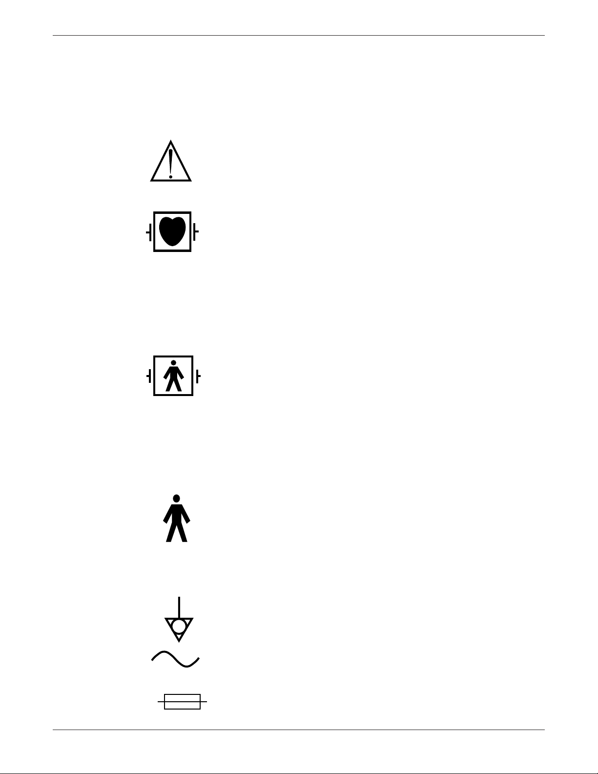
ATTENTION: Consult accompanying documents before using the
equipment.
TYPE CF APPLIED PART: Isolated (floating) connection suitable for
intentional external and internal application to the patient including direct cardiac application. “Paddles” outside the box indicate the
applied part is defibrillator proof.
Medical Standard Definition: F-type applied part (floating/isolated)
complying with the specified requirements of IEC 601-1/UL 26011/CSA 601.1 Medical Standards to provide a higher degree of
protection against electric shock than that provided by type BF
applied parts.
TYPE BF APPLIED PART: Isolated (floating) connection suitable for
intentional external and internal application to the patient excluding direct cardiac application. “Paddles” outside the box indicate the
applied part is defibrillator proof.
Medical Standard Definition: F-type applied part (floating/isolated)
complying with the specified requirements of IEC 601-1/UL 26011/CSA 601.1 Medical Standards to provide a higher degree of
protection against electric shock than that provided by type B
applied parts.
TYPE B APPLIED PART: Non-isolated connection suitable for intentional external and internal application to the patient excluding
direct cardiac application.
Medical Standard Definition: Applied part complying with the
specified requirements of IEC 601-1/UL 2601-1/CSA 601.1 Medical
Standards to provide protection against electric shock, particularly
regarding allowable leakage current.
Equipotentiality
Alternating current (AC)
Fuses
SMART-PAC TRANSPORT DISPLAY
403596-036
Revision Eviii
Page 11
Introduction
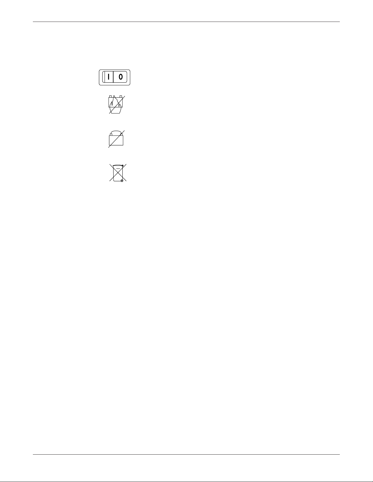
Power; I = ON; O = OFF
Explosion hazard; Do NOT incinerate battery.
Do NOT directly connect the negative and the positive terminals of
the battery.
Recycle internal battery.
Revision E
SMART-PAC TRANSPORT DISPLAY
403596-036
ix
Page 12

➔ Safety Information
Introduction
Warnings, Cautions, and
Notes
Danger
Warning
Caution
Warnings, cautions, and notes are used in this manual to provide
additional information to service personnel.
DANGER
Danger indicates an imminent hazard which, if not
avoided, will result in death or serious injury.
WARNING
Warning indicates a potential hazard or unsafe practice
which, if not avoided, could result in death or serious
injury.
CAUTION
Caution indicates a potential hazard or unsafe practice
which, if not avoided, could result in minor personal
injury or product/property damage.
Note
NOTE
Notes provide application tips or other useful
information to assure that you get the most from your
equipment.
SMART-PAC TRANSPORT DISPLAY
403596-036
Revision Ex
Page 13

Service Information
Introduction
Service Requirements
Equipment Identification
Follow the service requirements listed below.
• Refer equipment servicing to Marquette Medical Systems’
authorized service personnel only.
• Any unauthorized attempt to repair equipment under
warranty voids that warranty.
• It is the user’s responsibility to report the need for service to
Marquette Medical Systems or to one of their authorized
agents.
• Failure on the part of the responsible individual, hospital, or
institution using this equipment to implement a satisfactory
maintenance schedule may cause undue equipment failure
and possible health hazards.
• Regular maintenance, irrespective of usage, is essential to
ensure that the equipment will always be functional when
required.
Every Marquette Medical Systems device has a unique serial
number for identification. The serial number appears on the back of
the Tram Transport display. Refer to “Disassembly Procedure” in
Chapter 2, “Troubleshooting,” to disassemble the Tram Transport
display from the Smart-pac battery backpack.
Month
Manufactured
A = January
B = February
C = March
D = April
E = May
F = June
G = July
H = August
J = September
K = October
L = November
M = December
Revision E
D 1 XX 0005 G XX
Year
Manufactured
9 = 1989
0 = 1990
1 = 1991
2 = 1993
(and so on)
Product
Code
Two-character
product
descriptor
SMART-PAC TRANSPORT DISPLAY
Product
Sequence
Number
Manufacturing
number (of
total units
manufactured.)
403596-036
Division
F = Cardiology
G = Monitoring
Device
Characteristics
One or two letters
that further describe
the unit.
For example:
P = Prototype - not
conforming to
marketing
specification
R = Refurbished
equipment
S = Special product
documented under
SPECIALS part
numbers.
xi
Page 14

Introduction
How to Reach Us
Customer Support and Equipment Repair Information
If you have questions about your monitoring equipment or if you need service for equipment repair
call:
U.S.A. and Canada: 800-558-7044 (24-hour service)
Other countries: 561-575-5000 (During U.S. business hours only) or contact your
local sales and service reprsntative
Local sales and
service representative:__________________________________________________________________
(Name and phone number)
Ordering Service Parts
Service parts are items that are not expended in the normal operation of the product. They are
generally replacements for defective or malfunctioning items inside the product. Service parts include
PCB assemblies, electronic components, internal cables and harnesses, software or firmware, and
operator and service manuals.
A part number for the item to be replaced is necessary for ordering a service part. If the part number
for the desired item is unobtainable, the following will be necessary to order the item:
• model and serial number of the equipment
• part number/name of the assembly where the item is used,
• item name, and where applicable, reference designation (e.g., R13, S12, U32).
Supplies Information
Supply items are generally those items used during normal operation of a product. Leadwires,
electrodes, patient cables, printer paper, Aqua-Knot water traps, airway adapters, and calibration
gases are examples of supply items.
Make telephone inquiries about supply items at:
U.S. only: 800-558-5102
Outside U.S.: 561-575-5070 (or contact your local sales and service representative)
Address orders or inquiries in the U. S. to:
Marquette Medical Systems Service and Supplies
Attention: Supplies Department
100 Marquette Drive
Jupiter , Florida 33468-9100
Fax: 561-575-5050
SMART-PAC TRANSPORT DISPLAY
403596-036
Revision Exii
Page 15

Abbreviations
Introduction
A
AAMI Association for the
Advancement of
Medical
Instrumentation
Ahr ampere-hour
Al aluminum
Ampl amplifier
ANSI American National
Standards Institute,
Inc
AWG American Wire Gage
B
BDGH binding head
BP blood pressure
BPM beats per minute
C
Cap capacitor
Cer ceramic
CMOS complimentary metal-
oxide semiconductor
Comp composition
CSA Canadian Standards
Association
D
dc direct current
DDW Direct Digital Writer
Dia diameter
DIP dual in-line package
E
ECG electrocardiogram,
electrocardiograph
EPLD electronically
programmable logic
device
ESD electro static
discharge
F
FL Florida
FLH flat head
I
IEC International
Electrotechnical
Commission
in inch
Inc incorporated
K
K kilo, kilohm
kg kilogram
L
lb pound
LCD liquid crystal display
LED light-emitting diode
M
MEI Marquette
Electronics, Inc
MF metal film
MHz megahertz
mm millimeter
mm millimeter
mmHg millimeter of mercury
MMS Marquette Medical
Systems
MPE metallized
polycarbonate
epitaxial
mV millivolt
mW milliwatt
N
No number
Ntwk network
P
PAL programmable array
logic
PC printed circuit,
personal computer
pcb, PCB printed circuit board
PLCC plastic leaded chip
carrier
pn, PN part number
PNH pan head
POS positive
R
RAM random access
memory
Res resistor
Rgltr regulator
S
SD schematic diagram
sec second
SIP single in-line package
SM surface mount
SST stainless steel
T
Tant tantalum
Tram,
TRAM Transport Remote
Acquisition Monitor
TTL transistor-transistor
logic
U
UL Underwriters
Laboratories, Inc
V
V volt, voltage
V volt, voltage
Var variable
W
W watt, West
w/ with
w/o without
WI Wisconsin
WW wire wound
Z
ZIF zero insertion force
Other
˚C degrees Celsius
˚F degrees Fahrenheit
µF microfarad
Ω ohm
% percent
Revision E
SMART-PAC TRANSPORT DISPLAY
403596-036
➔
xiii
Page 16

For your notes
Introduction
SMART-PAC TRANSPORT DISPLAY
403596-036
Revision Exiv
Page 17

1 General Information
WHAT IS IN THIS CHAPTER?
This chapter describes the equipment and lists the technical
specifications.
Contents
About the Smart-pac Transport Display ............................. 1-2
Caring for Your Smart-pac Battery Pack ............................ 1-5
Technical Specifications ...................................................... 1-7
Revision E
SMART-PAC TRANSPORT DISPLAY
403596-036
1-1
Page 18
General Information
TRIM KNOB
BP ZERO
FREEZE
ALARM RESET
CONTRAST
T1
T2
+
-
R
E
S
T
M
P
E
C
G
70
P
A
2
34/ 14
( 22 )
40
23.4°C
39.4°C
II
1X
150
AR1
0
60
PA2
0
RESP
ICU-5
9-JAN-92 14:36
ALARMS OFF
ALARM
PAUSE
MONITOR DISPLAY
HELP
TRENDS GRAPH
OFF
N
B
P
120/ 80
( 94 )
A
R
1
137/ 73
( 95 )
16:08
LEAD II
mmHg
*
marquette
About the Smart-pac T ransport Display
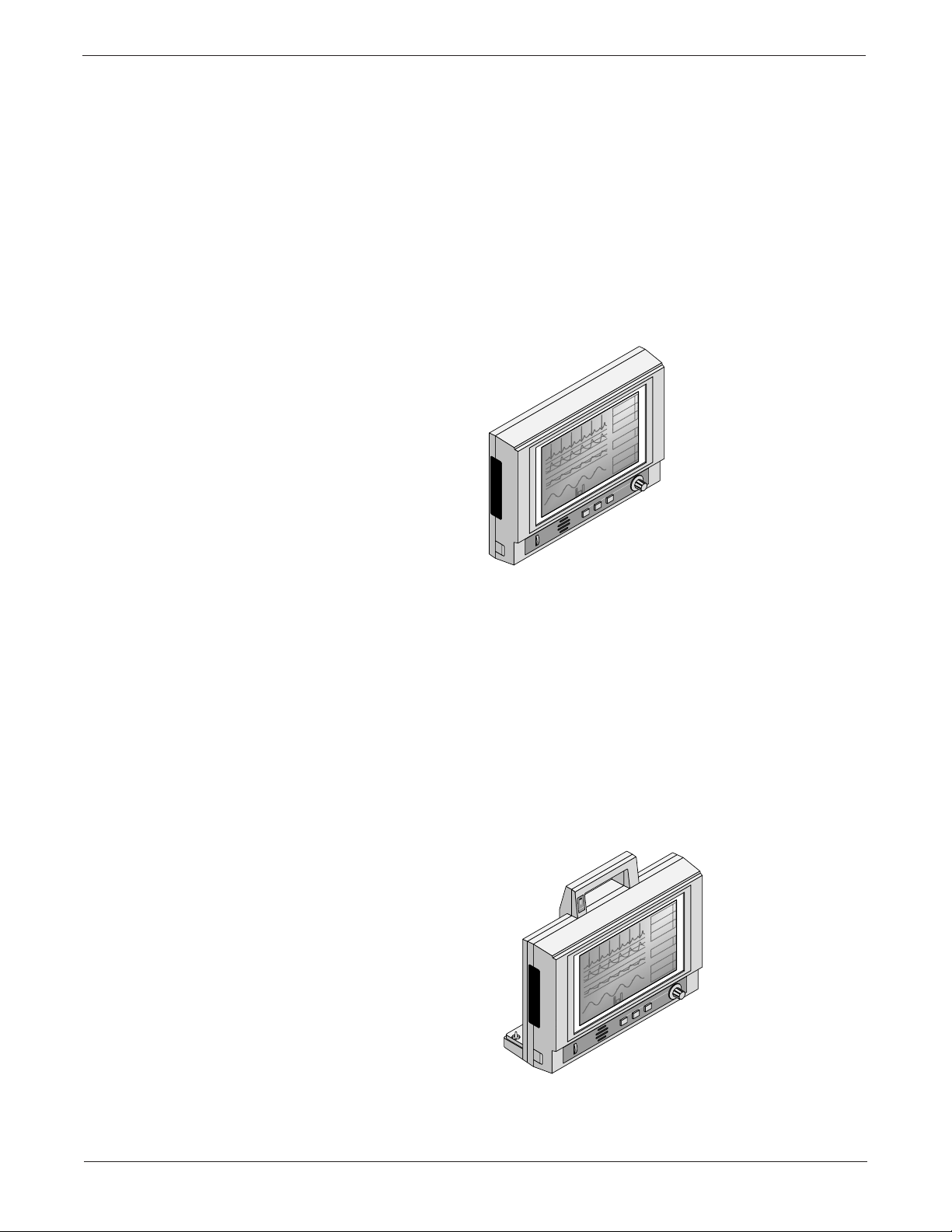
What is a Tram T ransport
Display?
In a Tram Critical Care Monitoring system, bedside and surgical
monitors use Tram modules to collect patient data at the bedside
area. The Tram Transport display presents the patient vital signs
and waveforms collected by the Tram module on a backlit,
supertwist LCD display. The name Tram Transport Display refers
to the display only. For more details about the Tram Transport
display, refer to chapter six in this manual.
What is a Smart-pac
Transport Display?
1-2
When a Tram Transport display is connected to the Smart-pac
battery backpack, the entire unit is referred to as a Smart-pac
Transport display. The Tram module is then connected to the
Smart-pac transport display when a patient is transported from one
hospital area to another. For more details about the Smart-pac
Transport display, refer to Chapter Five, “Smart-pac Transport
Display,” in this manual.
9-JAN-92 14:36
TRENDS GRAPH
FREEZE
E
C
G
70
*
A
R
1
P
( 95 )
137/ 73
A
2
34/ 14
( 22 )
N
B
P
( 94 )
120/ 80
mmHg
R
16:08
E
S
40
T
M
T1
P
T2
23.4°C
LEAD II
39.4°C
OFF
TRIM KNOB
BP ZERO
marquette
Revision E
CONTRAST
SMART-PAC TRANSPORT DISPLAY
403596-036
BATTERY
CHARGING
ALARMS OFF
ICU-5
II
1X
150
AR1
0
60
HELP
PA2
0
-
+
RESP
MONITOR DISPLAY
ALARM
ALARM RESET
PAUSE
➔
Page 19
General Information
➔ About the Smart-pac Transport Display
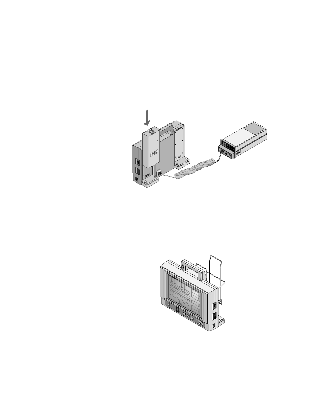
What is a Smart-pac Battery
Backpack?
By sliding a Smart-pac battery pack or power supply into either slot
at the back of the Smart-pac Transport display, both the Tram
module and display receive power. Pictured below is a Smart-pac
Transport Display with the battery backpack connected to a Tram
module. For more details about the Smart-pac Battery backpack,
refer to “Caring for Your Smart-pac Battery Pack” on the following
pages and in Chapter 10 in this manual.
I
O
WRITER DISPLAY POWER
For more details about the Smart-pac charger and power supply,
refer to the Smart-pac Charger Service Manual, (pn 403596-030) or
Smart-pac Power Supply Service Manual, (pn 403596-033).
What is a module holder?
How do I graph the
waveforms?
Pictured below is the Smart-pac Transport display with battery
pack and module holder assembly. For more details about the
module holder assembly, refer to Chapter 10 in this manual.
BATTERY
CHARGING
ICU-5
II
1X
ALARMS OFF
150
AR1
0
60
PA2
0
RESP
ALARM
PAUSE
CONTRAST
CONTRAST
MONITOR DISPLAY
9-JAN-92 14:36
marquette electronics
mmHg
16:08
+
HELP
-
TRENDS GRAPH
DANGER Risque d'explosion. Ne pas employer en presence d'anesthesiques inflammables.
LEAD II
OFF
ALARM RESET
FREEZE
BP ZERO
137/ 73
120/ 80
23.4°C
39.4°C
*
70
E
C
G
( 95 )
A
R
34/ 14
1
( 22 )
P
A
2
( 94 )
N
B
I
P
40
TRIM KNOB
marquette
O
R
E
S
T1
T
M
T2
P
WRITER DISPLAY POWER
The Smart-pac Transport display may also connect to a Direct
Digital Writer (DDW) for graphing patient data. The following pages
describe the DDW connector. To use the Smart-pac with a DDW,
refer to the appropriate Smart-pac transport display operator’s
manual.
➔
SMART-PAC TRANSPORT DISPLAY
403596-036
1-3Revision E
Page 20
General Information
➔ About the Smart-pac Transport Display
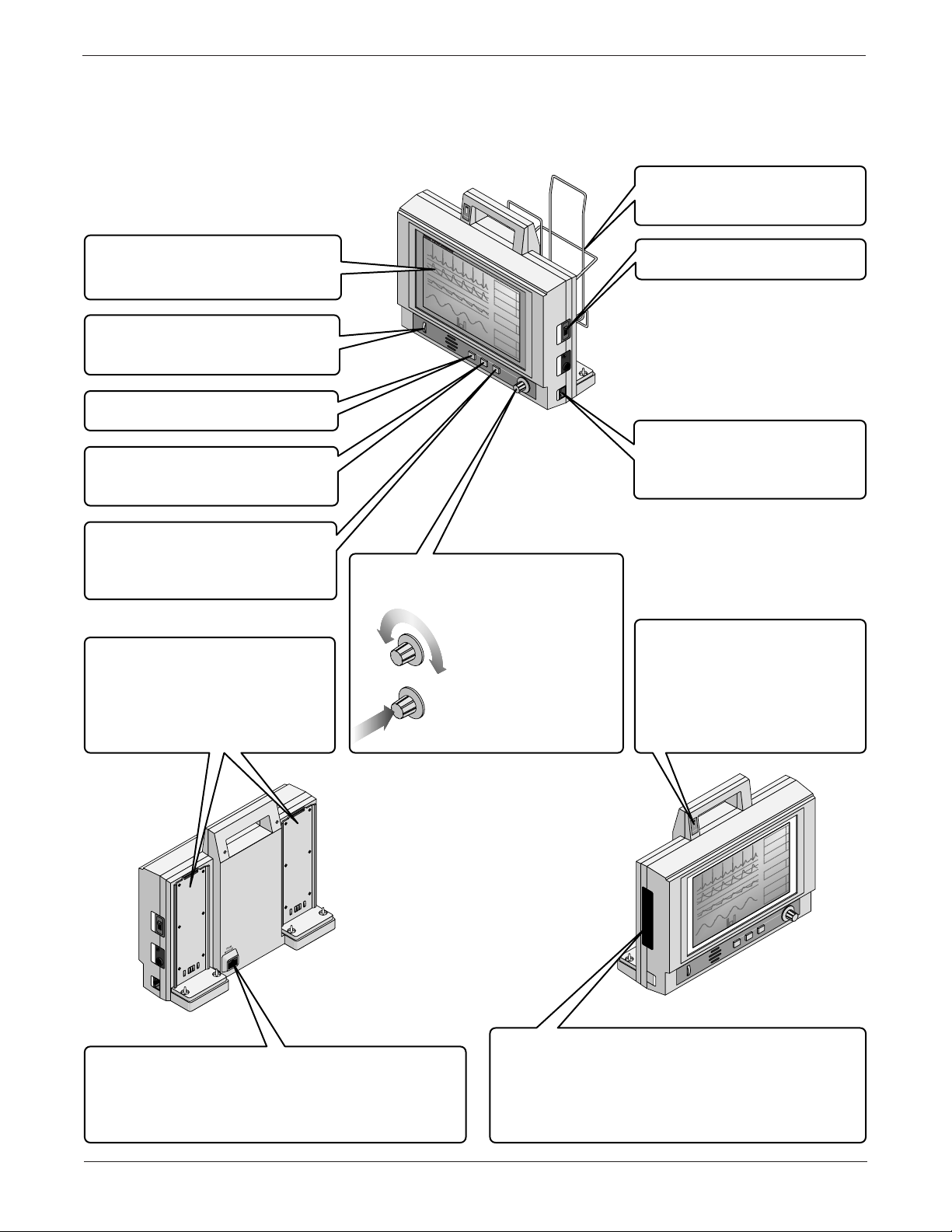
Parts of the Smart-pac
Transport Display
Display. A fluorescent-backlit,
double super-twisted LCD
display for showing patient data.
CONTRAST
control to get the best image for
your viewing angle.
ALARM RESET
key to clear alarms.
FREEZE
stop the waveforms on the
display.
BP ZERO
set the zero reference point of
all pressure inputs for the Tram
module.
Smart-pac Rails. Slide a
Smart-pac battery pack or
power supply onto one or both
of these to supply the transport
display and Tram module with
power.
Control. Adjust this
Key. Press this
Key. Press this key to
Key. Press this key to
BATTERY
CHARGING
ICU-5
II
1X
ALARMS OFF
150
AR1
CONTRAST
TRIM KNOB
0
60
PA2
0
RESP
ALARM
PAUSE
CONTRAST
9-JAN-92 14:36
marquette electronics
*
70
E
137/ 73
C
G
( 95 )
A
R
MONITOR DISPLAY
mmHg
16:08
+
HELP
-
TRENDS GRAPH
DANGER Risque d'explosion. Ne pas employer en presence d'anesthesiques inflammables.
LEAD II
OFF
ALARM RESET
FREEZE
BP ZERO
120/ 80
23.4°C
39.4°C
34/ 14
1
( 22 )
P
A
2
( 94 )
N
B
I
P
40
TRIM KNOB
marquette
O
R
E
S
T1
T
M
T2
P
WRITER DISPLAY POWER
Control. Use this
control to choose items from the
menu at the bottom of the display.
Rotate the control
until the item that you
want is highlighted.
Press the control to
select the highlighted
item.
Module Holder. The Tram
module is usually stored in
here during transport.
POWER
Switch. Turns the
transport display on and off.
DDW
Connector. Plug a
DDW (Direct Digital Writer) in
here to graph the patient’s
vital signs and waveforms.
CHARGING
Indicator. If you
install a Smart-pac battery
pack on one rail, and a
Smart-pac power supply on
the other rail, this indicator
lights to show when the
battery is charging.
I
O
WRITER DISPLAY POWER
TRAM MODULE
Connector. Make sure you plug
the Tram module into this connector. If you plug
it into one of the other connectors, you’ll see a
big
COMMUNICATION FAILURE
message on the
display.
1-4
SMART-PAC TRANSPORT DISPLAY
403596-036
9-JAN-92 14:36
TRENDS GRAPH
FREEZE
E
C
G
70
*
A
R
1
P
( 95 )
137/ 73
A
2
34/ 14
( 22 )
N
B
P
( 94 )
120/ 80
mmHg
R
16:08
E
S
40
T
M
T1
P
T2
23.4°C
LEAD II
39.4°C
OFF
TRIM KNOB
BP ZERO
marquette
SOFTWARE CARTRIDGE
BATTERY
CHARGING
ALARMS OFF
ICU-5
II
1X
150
AR1
0
60
HELP
PA2
0
-
+
RESP
MONITOR DISPLAY
ALARM
ALARM RESET
PAUSE
CONTRAST
Cover. The software
cartridge lives under this cover. You might
replace it if you do your own software updates.
If you do, make sure you read the Update
Instructions that come with the new software
cartridge before you replace it.
Revision E
➔
Page 21
General Information
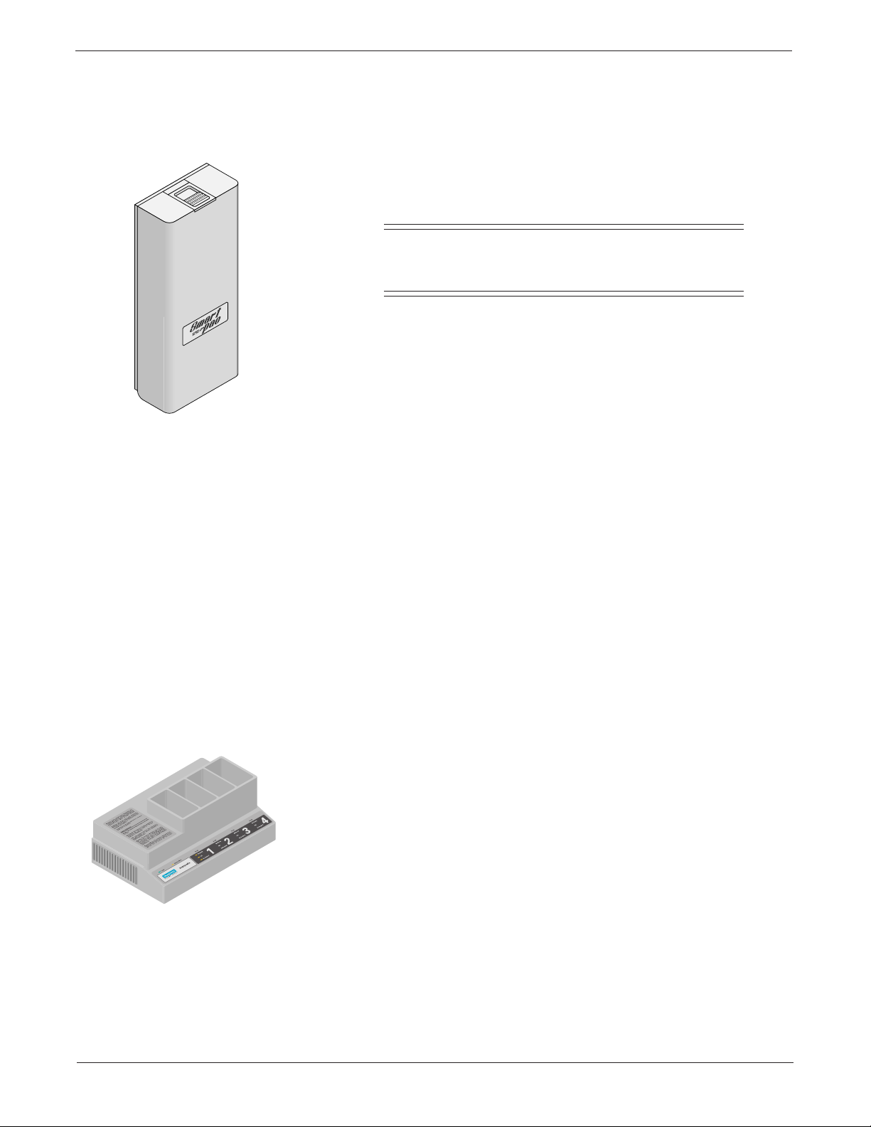
Caring for Your Smart-pac Battery Pack
The Smart-pac battery pack is shipped fully charged. To ensure
optimum performance, please recharge in a Smart-pac Charger
before the battery is put into service.
NOTE
Always make sure you fully charge this battery pack
before you use it with a patient.
The following tips should help you get the longest life and best
performance from your Smart-pac battery pack.
Storing the Battery Pack
Using the Smart-pac
Charger
We recommend that you store the battery pack in a Smart-pac
battery charger when you are not using it. The shelf life of the
battery is four weeks, and it is very important that you fully charge it
in a Smart-pac battery charger at least once every four weeks.
Smart-pac 2 batteries require the following Smart-pac Backpack
and Smart-pac Charger software:
• Smart-pac Backpack Version 2A or later.
• Smart -pac Charger V ersion 2A or later.
• Series 7240 Charger V ersion 2A or later.
• Series 7250 Charger V ersion 1A or later.
If you place your battery pack in a Smart-pac charger, and its
voltage is below 10 volts, the charger NOT READY indicator should
light for about 10 minutes while it trickle-charges the battery.
It takes about 75 minutes to charge a fully discharged Smart-pac
battery pack with a Smart-pac charger .
When you place your battery pack into a Smart-pac charger, and
you have not exercised the battery pack for 50 days or 100 charge
cycles, the charger EXERCISE indicator lights. exercising the
battery pack prolongs its life by first charging the battery, fully
discharging it,and then fully charging it again.
Press the EXERCISE key on the charger rear panel to start the
exercise cycle. An exercise cycle may take up to three hours,
depending on the battery pack’s capacity. The charger always fully
charges all batteries before it begins any exercise cycles.
SMART-PAC TRANSPORT DISPLAY
403596-036
1-5Revision E
Page 22
General Information
➔ Caring for Y our Smart-pac Battery Pack
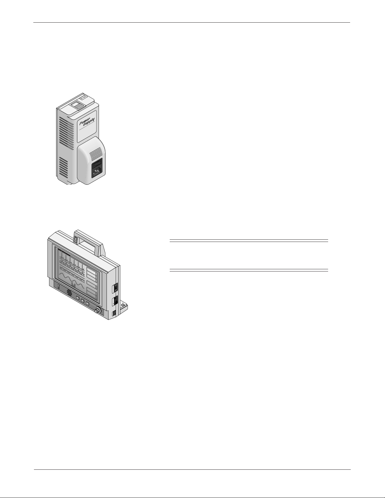
Using a Smart-pac Power
Supply
Using a Smart-pac T ransport
Display
BATTERY
CHARGING
ICU-5
II
1X
ALARMS OFF
150
AR1
0
60
PA2
0
RESP
ALARM
PAUSE
DANGER Explosion risk if used with flammable anesthetics.
CONTRAST
US Patent 4,715,385.
Other Patents Pending
MONITOR DISPLAY
9-JAN-92 14:36
marquette electronics
mmHg
16:08
+
HELP
-
TRENDS GRAPH
DANGER Risque d'explosion. Ne pas employer en presence d'anesthesiques inflammables.
LEAD II
OFF
ALARM RESET
FREEZE
For use by qualified medical personnel only. See operator's guide for instructions.
BP ZERO
137/ 73
120/ 80
23.4°C
39.4°C
*
70
E
C
G
( 95 )
A
R
34/ 14
1
( 22 )
P
A
2
( 94 )
N
B
I
P
O
40
TRIM KNOB
DISPLAY POWER
R
E
S
T1
T
M
T2
P
REMOTE CONTROL
WRITER
If you use a Smart-pac power supply with your Smart-pac transport
display, the power supply can charge a Smart-pac battery pack
while it runs the transport display. However, it can take up to 16
hours to fully charge the battery.
Even if you use a power supply with your battery pack and
transport display, you still need to place your battery pack in a
Smart-pac battery charger at least once every four weeks, so the
battery charger can exercise your battery pack.
If the battery pack does not work with your Smart-pac display,
make sure the battery backpack on your transport display has the
latest version of software. Call your sales representative for software
updates.
NOTE
It is very important to make sure you fully charge this
battery pack before you use it on a patient.
For technical advice concerning your monitoring system, contact
Tech Support—Monitoring Hardware.
1-6
SMART-PAC TRANSPORT DISPLAY
403596-036
➔
Revision E
Page 23

Technical Specifications
Performance Specifications
Size: 9-inch diagonal
Type: Fluorescent backlit passive monochrome LCD
Resolution: 640 x 400 pixels
Number of traces: 4
Number of seconds/trace: 5
Sweep speed: 24.8 mm/sec, crystal controlled ±0.1%
Operating time: Using one Smart-pac 2.4-Ahr battery pack
Typical: 75 to 105 minutes with battery charged to 100% of rated capacity
Nominal: 60 to 75 minutes with battery charged to 80% of rated capacity
Environmental Specifications
Operating Conditions
Ambiant temperature: 10˚C to 35˚C (50˚F to 95˚F)
Relative humidity: 40% to 95% (noncondensing)
Storage Conditions
Ambiant temperature: –10˚C to 50˚C (15˚F to 122˚F)
Relative humidity: 0% to 95% (noncondensing)
General Information
Power Requirements
Voltage: 12V DC
Power: 6 watts
Physical Specifications
Height: 25.4 cm (10 in)
Width: 31.8 cm (12.5 in)
Depth: 9.5 cm (3.3 in)
Approx. weight: 5.7 kg (12.5 lb)
Certification
UL: UL544 Listed
CSA: CSA No 125 Certified
IEC: IEC 601-1 Certified
(with two batteries)
➔
SMART-PAC TRANSPORT DISPLAY
403596-036
1-7Revision E
Page 24

General Information
➔ T echnical Specifications
Classification
The Smart-pac Power Supply is classified, according to IEC 601-1,
as:
Type of protection against
electrical shock: Class I Equipment or Internally Powered Equipment
Degree of protection against
electrical shock: Not Marked
Degree of protection against
harmful ingress of water: Ordinary Equipment (enclosed equipment without protection
against ingress of water)
Degree of safety of application
in the presence of a flammable
anesthetic mixture with air or
with oxygen or nitrous oxide: Equipment not suitable for use in the presence of a flammable
anesthetic mixture with air or with oxygen or nitrous oxide.
Method(s) of sterilization or
disinfection recommended
by the manufacturer: Not Applicable
Mode of operation Continuous operation
1-8
SMART-PAC TRANSPORT DISPLAY
403596-036
Revision E
Page 25

2 Troubleshooting
WHAT IS IN THIS CHAPTER?
This chapter contains information that can help you repair the
Smart-pac transport display more effectively. It includes
information about some types of components that are used in
Smart-pac transport display, but not yet widely used in the field,
and some troubleshooting tips for communication problems.
Contents
Considerations for Special Components ............................. 2-2
Replacing the LCD Display.................................................. 2-4
Disassembly Procedure ........................................................ 2-5
Problems and Solutions..................................................... 2-11
Revision E
SMART-PAC TRANSPORT DISPLAY
403596-036
2-1
Page 26

Troubleshooting
Considerations for Special Components
CMOS Components
The Smart-pac transport display makes extensive use of CMOS
components. CMOS components are more immune to noise and
consume less power than standard TTL or NMOS components.
However , CMOS components are inherently more susceptible to
electrostatic discharge (ESD) damage than other semiconductors.
ESD damage, usually a subtle weakening of semiconductor
junctions, can range from corruption of digital memory to
catastrophic failure and can render one (or more) components
permanently unusable. Although it is more common for CMOS
components to fail from ESD damage, no semiconductor device is
completely immune to ESD damage.
The inputs and outputs of the Smart-pac transport display are
protected from ESD damage; they are no more susceptible to ESD
damage during normal operation than other devices. However, when
you service the equipment, the components within are exposed to
several sources of static electricity, ranging from human hands to
improperly grounded test equipment. For this reason, it is
suggested that all service workstations be as static-free as possible.
The following guidelines can help make your workstation more
resistant to the damage that can be caused by static electricity.
• A grounded, antistatic wristband (3M part number 2046 or
equivalent) or heelstrap should be worn at all times when
repairing assemblies containing semiconductors.
• Discharge any built up static charge before handling
semiconductors or assemblies containing semiconductors.
• Use only properly grounded soldering and test equipment.
• Use a static-free surface (3M part number 8210 or equivalent)
when working on assemblies containing semiconductors.
• Do not remove semiconductors or assemblies containing
semiconductors from antistatic containers (bags) until needed.
• Make sure power to an assembly is turned off before removing
or inserting a semiconductor.
• Do not slide semiconductors or assemblies containing
semiconductors across any surface.
• Do not touch semiconductor leads unless absolutely
necessary.
• Semiconductors and assemblies containing semiconductors
should be stored only in antistatic bags or boxes.
Although these items cannot ensure a 100% ESD-free workstation,
they can greatly reduce the failure rate of any semiconductors that
are serviced.
SMART-PAC TRANSPORT DISPLAY
403596-036
➔
Revision E2-2
Page 27
Troubleshooting
➔ Considerations for Special Components
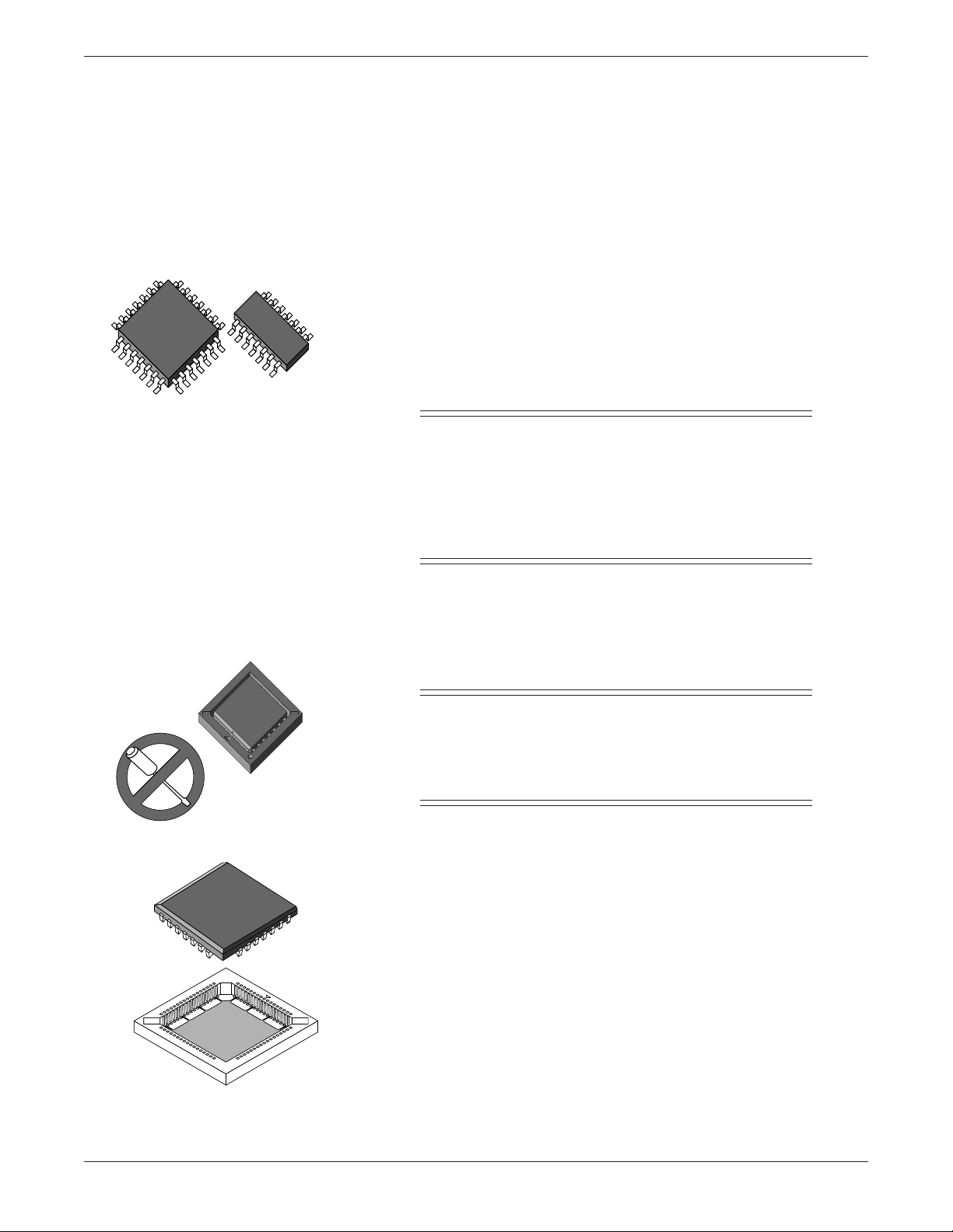
Surface Mounted
Components
Plastic Leaded Chip Carriers
Surface mounted components aid in miniaturizing the Smart-pac
transport display.
Surface mounted integrated circuits have legs soldered to
rectangular pads on the surface of the circuit board, rather than
legs that are inserted into holes that go through the circuit board.
Surface mounted integrated circuits can have legs on either two or
four sides of the chip.
Surface mounted resistors, capacitors, and diodes usually have no
legs at all – conductive parts of their bodies are soldered directly to
the circuit board.
CAUTION
Surface mounted components were not designed to be
removed and replaced with standard soldering equipment. Removing a surface mounted component with a
conventional soldering iron could destroy the circuit
board. Special equipment is required to remove and
replace these items.
Plastic leaded chip carriers (PLCCs) also save space. PLCCs have
conductors on all four sides and are usually used with special
sockets. They do not have legs like a conventional integrated circuit,
but rather “loops” that make contact with the socket or circuit
board when they are inserted.
CAUTION
Removing and inserting PLCCs requires a special tool
(Burndy QILEXT-1 or equivalent). If you use a screwdriver to remove or replace a PLCC, you may damage
the PLCC or the socket.
If you must troubleshoot the circuitry under the PLCC socket,
carefully remove the PLCC. Next, carefully break out the square
socket bottom with a knife so you can probe the circuit board
below.
When you finish troubleshooting, make sure to replace the square
bottom socket before you insert the PLCC again or replace the
whole socket with the correct socket replacement part. Refer to the
appropriate parts list in this manual. The socket provides necessary
spacing between the bottom of the PLCC and the circuit board.
Revision E
SMART-PAC TRANSPORT DISPLAY
403596-036
2-3
Page 28

Replacing the LCD Display
If your LCD display is damaged, you need to order one of three
Smart-pac Display Retrofit kits available to replace it. The serial
number located on the back of the Tram Transport display
determines which of the three replacement kits you need.
To view the serial number, use the disassembly procedure provided
later in this chapter to separate the Smart-pac battery backpack
from the Tram Transport display. For an explanation on how to
read the serial number digits, refer to “Equipment Identification” in
the Introduction of this manual.
• If the product code of the serial number is “JW,” order retrofit
kit, pn 414091-001. This kit includes detailed instructions
about how to rework the display processor PCB, pn 85638002 revision M or later . If your display processor PCB is an
earlier version, the PCB cannot be reworked and must be
replaced. Call Tech Support at 1-800-558-7822 for details.
Troubleshooting
• If the product code of the serial number is “LG” and product
sequence number is from 001 to 190 (except 186), order
retrofit kit, pn 414091-002. This kit includes a new flex circuit
and LCD display. The new flex circuit is required because the
older flex circuit was soldered directly to the LCD display and
will be discarded with it. Y ou may use the disassembly
procedure included in this chapter to replace your LCD
display.
• If the product code of the serial number is “LG” and the
product sequence number is 186, 191 or later, order retrofit
kit, pn 414091-003. This kit includes only the LCD and you
may use the disassembly procedure included in this chapter
to replace your LCD display.
SMART-PAC TRANSPORT DISPLAY
403596-036
Revision E2-4
Page 29
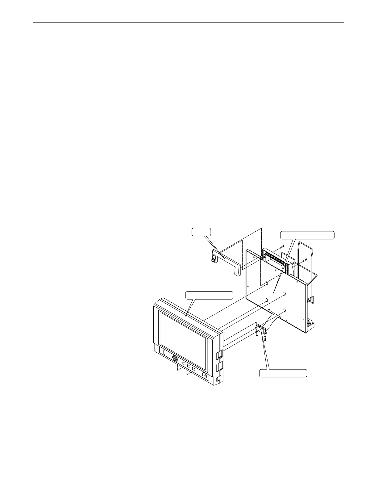
Disassembly Procedure
Handle
Smart-pac Battery Backpack
Ribbon Cable Connector
Tram Transport Display
Troubleshooting
Remove Optional Smart-pac
Battery Backpack
These are the recommended steps to disassemble the major
components of the Smart-pac Transport display. Keep all hardware
for re-assembly.
1. Remove the two screws from the rear of the handle and
remove the front of the handle from the Smart-pac battery
backpack.
2. Remove the two screws and washers recessed in the bottom of
the Tram Transport display that secure the ribbon cable
connector from the Smart-pac battery backpack to the Tram
Transport display.
3. Disconnect the ribbon cable connector from the Tram
Transport display board-edge connector.
4. Slide the Smart-pac battery backpack downward to disengage
the mounting buttons from the keyhole-shaped mounting
slots located on the Smart-pac battery backpack front cover.
5. Car efully separate the Tram Transport display from the
Smart-pac battery backpack.
Revision E
SMART-PAC TRANSPORT DISPLAY
➔
2-5
403596-036
Page 30

➔ Disassembly Procedure
Troubleshooting
Disassemble the Tram
Transport Display
1. Remove the six screws from around the rear perimeter of the
Tram Transport display that secures the front and back
display case. Refer to the figure on the next page.
CAUTION
For the next step, there are cables and connectors
inside the Tram Transport display that could possibly
be stressed when the front and back display cases are
separated. As you look at the unit, open it slightly on the
right first instead of opening it along the top edge to
avoid ripping the flex circuit.
2. Car efully separate the case front and back display cases so
you do not damage the cables or connectors.
3. Disconnect the cables/harnesses listed below that provide
interconnection for the display processor PCB and front panel
switches to the display assembly. Refer to the figure on the
next page.
• Disconnect the horizontal 60-pin connector and ribbon
cable from the front display case.
• At the display processor PCB, slide the slip-ring lock
mechanism of the horizontal 20-pin zero insertion force
(ZIF) connector . Gently pull the flex cir cuit from the ZIF
connector ,
• Disconnect the 3-pin display power cable from the
connector on the display processor PCB (disengage the
interlock to release the cable harness).
SMART-PAC TRANSPORT DISPLAY
403596-036
➔
Revision E2-6
Page 31

➔ Disassembly Procedure
Use the figure below to assist with the disassembly procedure.
Troubleshooting
Case Front
5 Screws
Display Assembly
Display
Processor
PCB
Backlight
Power Cable
6 Screws
Ground
20-Pin
ZIF
Connector
Connector
60-Pin
Case Back
6 Screws
Serial Number
3-Pin
Backlight
Power
Connector
➔
Revision E
SMART-PAC TRANSPORT DISPLAY
403596-036
2-7
Page 32

➔ Disassembly Procedure
4. Remove the two screws and washers that secure the center
5. Remove the screw which secures a ground cable ring
6. Remove the three outside screws to replace the display
7. To replace the display processor PCB, remove the five screws
8. While using electrostatic discharge (ESD) protection, remove
Perform any necessary service at this time.
Troubleshooting
support bracket to the display front case.
connector to the display mounting bracket.
assembly.
securing the display processor PCB to the back display case.
the display processor PCB.
Backlight Power
Cable
Display
Assembly
Ground
Wire
Center Support
Bracket
Remove Four
Corner Screws
SMART-PAC TRANSPORT DISPLAY
403596-036
➔
Revision E2-8
Page 33

➔ Disassembly Procedure
Troubleshooting
Re-assemble the Tram
Transport Display
1. Use a lint-free cloth to clean the inside of the protective filter
lens affixed to the front display case. Remove fingerprints,
dust, or smudges from the protective filter lens. Carefully wipe
the outer lens of the retrofit display assembly to remove
fingerprints, dust, or smudges as well.
CAUTION
Apply very light pressure with a continuous motion
over the new display outer lens to remove any fingerprints, dust or smudges. Do not use excessive pressure
when wiping it down because it may damage the
display.
NOTE
Protect the clean surfaces. Fingerprints, dust, or
smudges left on the surfaces mentioned above are
annoyingly visible when the Tram Transport Display is
turned ON when you re-assemble to unit.
2. Install the new display assembly provided in the kit into the
front display case.
NOTE
Orient the new display assembly with the backlight
power cable to the left and the flex circuit to the right of
the display assembly when viewed from the inside of
the front display case.
Revision E
3. Fasten the four screws to the corners of the new display
assembly with the ground cable in the lower left corner when
viewed from the inside of the front display case. Center the
new display assembly with respect to the rectangular opening
in the front display case.
4. Remount the center support bracket with the two screws in
the mounting holes in the front display case.
5. Install the display processor PCB into the back display case
and secure with the hardware you removed earlier. Attach the
other end of the ground cable-ring connector to the mounting
hole of the display processor PCB lower-right corner last.
Orient the ground cable so that it does not interfere with the
front and back display case when assembled together.
6. Connect the cables and harnesses listed below that provide
interconnection between the display processor PCB, front
panel switches, and display assembly.
• Observing correct orientation, connect the two-wire
backlight power cable to the connector on the display
processor PCB.
SMART-PAC TRANSPORT DISPLAY
403596-036
➔
2-9
Page 34

➔ Disassembly Procedure
Troubleshooting
➔ Re-assemble the T ram
Transport Display
• Attach the 60-pin flex circuit connector from the control
panel assembly to connector on the display processor
PCB.
• Carefully insert the 20-pin flex circuit from the display
assembly into ZIF connector on the display processor
PCB with the contact points facing you (away from the
PCB). Ensure the flex circuit aligns properly in the
connector . Orient the flex circuit so that there are no
twists and make sure that it is centered and straight
with respect to the ZIF connector. Secure the flex circuit
into the connector by sliding the slip-ring mechanism
toward the base of ZIF connector locking the flex circuit
into place.
8. W ith the back case on the bottom, carefully fold all flex
circuits, ribbon cables, and cable harnesses into a position
where they cannot get kinked, nicked or compressed.
CAUTION
Do not pinch any internal flex circuits, ribbon cables,
or cable harnesses. Make sure that all internal cables
do not obstruct any of the screws used to secure the
front and back display cases.
Connect Optional Smart-pac
Battery Backpack
Completion
9. Seat the power switch and external connector mounting plates
into the respective openings provided in the front and back
display cases.Secure the front and back display cases with the
hardware you removed earlier.
1. For the optional Smart-pac Battery Backpack, connect the
ribbon cable connector from the Smart-pac Battery Backpack
to the Tram Transport display with the two screws and lock
washers.
2. Align and insert the mounting buttons located on the display
case back into the keyhole-shaped mounting slots on the
Smart-pac Battery Backpack front cover. Slide the Tram
Transport Display down as far as it can go. The tops and
bottoms of the Tram Transport Display and Smart-pac
Battery Backpack should be flush with respect to each other.
3. Install the BATTERY CHARGING indicator LED into the
mounting hole on the Smart-pac Battery Backpack front
handle piece and align the LED cable harness so it cannot
interfere with installation of the handle.
4. Align the front handle piece with the Smart-pac Battery
Backpack housing and secure the front handle piece with
hardware previously removed. Once the front handle piece is
installed, the Tram Transport Display is locked in place to the
Smart-pac Battery Backpack.
Perform the Check Procedure found in Chapter 4, “Preventive
Maintenance,” in this manual before returning to service.
SMART-PAC TRANSPORT DISPLAY
403596-036
Revision E2-10
Page 35

Problems and Solutions
Here are a couple of problems that Marquette service personnel
have encountered with Smart-pac transport displays, and
descriptions of how they solved them.
Troubleshooting
Problem:
Solution:
The transport display shows a big COMMUNICATION FAILURE
message and won’t display any waveforms.
Using the wrong connector on the transport display usually causes
this problem. Make sure that you’re plugging the Tram module into
the connector on the backof the transport display. The two
connectors on the sides do not work for the Tram module.
I
O
WRITER DISPLAY POWER
If you use the correct connector but you still see the
COMMUNICATION FAILURE message, try the following steps.
• Unplug the cable between the Tram module and the transport
display and plug it back in.
• Replace the cable between the Tram module and the transport
display with a known good one.
• Reseat the connector on the bottom of the transport display.
It connects the transport display assembly to the battery
backpack assembly, and all communication signals between
the Tram module and transport display go through it.
• The transport display is designed to withstand the rigors of
transporting patients, but sometimes connectors disconnect
and integrated circuits unseat. Disassemble the battery
backpack assembly. When you’re inside it, disconnect and
reseat all of the connectors. If you have a PLCC extractor, you
can also carefully remove and reseat microcontroller U3 on
the battery interface PCB. If this step works, make sure that
you do the Checkout Procedures listed in Chapter 4,
“Preventive Maintenance.”
➔
Revision E
SMART-PAC TRANSPORT DISPLAY
403596-036
2-11
Page 36

➔ Problems and Solutions
Troubleshooting
➔ Solution:
Problem:
Solution:
• Take the battery backpack assembly off of the transport
display assembly, and try it on a different transport display.
Likewise, you can try a different battery backpack assembly
on the transport display assembly.
∞ If the problem is with the battery backpack assembly,
replace the battery interface PCB with a known good
one.
∞ If the problem is with the transport display assembly,
replace the display processor PCB with a known good
one.
The transport display won’t turn ON.
• Adjust the CONTRAST control on the front panel. If this control
is turned all the way down, the transport display looks like it’s
been turned OFF.
• If you’re using Smart-pac battery packs to power the transport
display, make sure they are fully charged. Make sure the
READY light lights on the Smart-pac charger before you use
the battery pack with a transport display. If the EXERCISE
light is ON for the battery, make sure that you exercise the
battery pack before you use it again (press the EXERCISE
switch by the power cord connector on the Smart-pac
charger).
• If you just bought new battery packs, they were probably
Smart-pac II battery packs. If you want to use the new battery
packs, you might have to update the software in the battery
backpack assembly to version 2A or later . The Smart-pac
Battery Backpack V ersion 002 Update Instructions (pn 403596-
034) shows you how to do this.
• Remove the battery backpack assembly from the transport
display assembly and swap these items with ones from a
working transport display.
∞ If the problem is with the battery backpack assembly,
disassemble the battery backpack assembly. Once
inside it, disconnect and reseat all of the connectors. If
you have a PLCC extractor, you can also carefully
remove and reseat microcontroller U3 on the battery
interface PCB. If this step works, make sure that you do
the Checkout Procedures listed in Chapter 4, “Preventive
Maintenance.” If it doesn’t, swap the battery interface
PCB with a known good one.
∞ If the problem is with the transport display assembly,
replace the display processor PCB with a known good
one. If that doesn’t fix it, the problem is probably in the
LCD display itself.
SMART-PAC TRANSPORT DISPLAY
403596-036
Revision E2-12
Page 37

3 Calibration
WHAT IS IN THIS CHAPTER?
This chapter describes how and when to adjust the equipment.
It also describes the Smart-pac transport display’s internal
switches and jumpers.
There are only two circuit boards in the Smart-pac transport
display that have adjustments, switches, and jumpers: the
display processor PCB (pn 800814 or pn 85638) and the battery
interface PCB (pn 403861).
Contents
Display Processor PCB PN 800814...................................... 3-2
Display Processor PCB PN 85638 ........................................ 3-4
Battery Interface PCB PN 403861 ....................................... 3-9
Revision E
SMART-PAC TRANSPORT DISPLAY
403596-036
3-1
Page 38

Calibration
Display Processor PCB PN 800814
Audio V olume Adjustment
Variable resistor R32 sets the Smart-pac transport to display a
consistent volume level. The speaker volume is adjusted in the
factory to a particular amplitude.
NOTE
This is not a recommended field adjustment, but be
aware that changing the speaker assembly changes the
speaker volume.
If you perform checkout procedures on a transport display after a
repair and you notice that the alarm volume is much louder or
quieter than other transport displays in your hospital, adjust
variable resistor R32 to fix this problem.
CAUTION
Check the alarms after you adjust the speaker voltage.
If the adjustment is too high, it can overdrive the
speaker; if it is low, it can shut off the alarms.
R32
Revision E3-2
Page 39

Calibration
➔ Display Processor PCB PN 800814
Switch Settings
Set switches
according to
language
desired.
English
3456
There is one DIP switch on the display processor PCB. When you
replace a display processor PCB, make sure that the switches on
the new circuit board are correct. The figure below shows how to set
the switches on the new circuit board.
SwedishItalianFrench
3456
3456
12 12 12
3456
ONONON
DutchGermanSpanish
ONON
345612 12 12
ON
3456
ON
3456
12
Revision E
3-3
Page 40

Calibration
Display Processor PCB PN 85638
Earlier versions of the Tram Transport Display used the pn 8563800x display processor PCB. V ariable resistor R84 is used to set the
intensity of the fluorescent backlight to a consistent level in the
factory.
If you replace the LCD display assembly or any of the following
components on the display processor PCB, you should calibrate the
backlight level:
Q3 R84 R87
R100 T1 U69
Display Backlight Intensity
Adjustment
Do the following to calibrate the display backlight intensity:
1. Turn the transport display OFF.
2. Attach all cables to the display processor PCB. This includes
the cable to the backlight of the LCD display assembly, and
the cable to the battery backpack assembly.
3. Attach a digital voltmeter across resistor R100 on the display
processor PCB.
W ARNING
In the following step, apply power to the transport
display. When you apply power, the output side of
inverter T1 develops over 700 volts to dive the fluorescent backlight tubes in the LCD display assembly.
Make sure you do not touch inverter T1, connector
J828, or the bottom side of the circuit board while
power is applied.
4. Turn the transport display ON.
5. Adjust variable resistor R84 until the digital voltmeter reads
140 millivolts.
Revision E3-4
Page 41

Calibration
➔ Display Processor PCB PN 85638
➔ Display Backlight Intensity
Adjustment
Revision E
T1 R84 R100 U69 R87 Q3J828
3-5
Page 42

Calibration
➔ Display Processor PCB PN 85638
Audio V olume Adjustment
Variable resistor R31 is used to set the Smart-pac transport
displays to a consistent volume level. The speaker volume is
adjusted in the factory to a particular amplitude.
NOTE
This is not a recommended field adjustment, but be
aware that changing the speaker assembly changes the
speaker volume.
If you perform a checkout procedure on a transport display after a
repair and you notice that the alarm volume is much louder or
quieter than other transport displays in your hospital, you may
adjust variable resistor R31 to fix this problem.
W ARNING
Recheck the alarms after adjusting the speaker voltage.
Too high an adjustment will overdrive the speaker and
too low will shut off the alarms.
R31
Revision E3-6
Page 43

Calibration
➔ Display Processor PCB PN 85638
Jumper Settings
Memory size jumper
W1 should be in the
left position.
There are several jumpers on the display processor PCB. When you
replace a display processor PCB, always make sure that the
jumpers on the new circuit board are set correctly before you install
the PCB. The figure below shows how to set the jumpers on the new
circuit board.
Watchdog reset enable jumper W4
should be in the
bottom (EN)
position.
Processor/watchdog
clock enable jumper
W5 should be
installed.
DUART U19 clock
enable jumpers W6
and W13 should
both be installed.
Revision E
Display controller
U65 type jumper
W10 should be in
the left position.
Display controller
U65 clock select
jumper W14 should
be installed.
Display controller
U65 clock select
jumper W9 should
be in the left
position.
3-7
Page 44

Calibration
➔ Display Processor PCB PN 85638
Switch Settings
There are two sets of DIP switches on the display processor PCB.
When you replace a display processor PCB, make sure that the
switches on the new circuit board are correct. The figure below
shows how to set the switches on a new circuit board.
DIP Switch S2 sets
the language of the
Smart-pac transport
English
ON1234
DIP switch S1 is set according to
whether the transport display has
a battery backpack installed.
display’s software:
French
ON1234
Italian
ON1234
Swedish
ON1234
Series 7200 Tram transport
ON12
displays without battery
backpacks are set like this.
Spanish
ON1234
German
ON1234
Dutch
ON1234
Smart-pac transport displays
ON12
or Series 7200 Tram transport displays with battery
backpacks are set like this.
Revision E3-8
Page 45

Calibration
Battery Interface PCB PN 403861
Jumper Setting
The battery interface PCB doesn’t have any adjustments or
switches, but it does have one jumper. The watchdog clock disable
jumper, W1 , should not be installed. If you replace a battery
interface PCB, always make sure that the jumper on the new circuit
board is not installed before you install the PCB.
Watchdog clock disable jumper W1
Revision E
3-9
Page 46

For your notes
Calibration
Revision E3-10
Page 47

4 Preventive Maintenance
WHAT IS IN THIS CHAPTER?
This chapter contains preventive maintenance instructions for
the Smart-pac transport display. These instructions describe
how to care for your Smart-pac transport display and how to
make sure that it’s working properly.
Contents
Maintenance Schedule......................................................... 4-2
Inspection ............................................................................ 4-3
Cleaning ............................................................................... 4-4
Check Procedure.................................................................. 4-5
Preventive Maintenance Inspection Form ......................... 4-13
Revision E
SMART-PAC TRANSPORT DISPLAY
403596-036
4-1
Page 48

Maintenance Schedule
Preventive Maintenance
The Smart-pac transport display maintenance schedule must
include all of the items in this table.
What to do When to do it
Inspection Before you transport each patient.
Cleaning Before you transport each patient.
Checkout procedures When you first get your transport display,
every six months thereafter , and when you
remove or replace a circuit board.
W ARNING
Failure on the part of the responsible individual, hospital, or institution employing the uses of this monitoring equipment to implement a satisfactory maintenance schedule may cause undue equipment failure
and possible health hazards. Marquette Medical Systems does not in any manner assume the responsibility
for perfor ming the recommended safety tests, unless
an Equipment Maintenance Contract exists. The sole
responsibility rests with the individual or institution
using the equipment.
4-2
SMART-PAC TRANSPORT DISPLAY
403596-036
Revision E
Page 49

Inspection
Preventive Maintenance
Y ou should inspect the Smart-pac transport display each time you
transport a patient. Follow these guidelines when you inspect the
display :
• Inspect the Smart-pac transport display for obvious physical
damage and replace the damaged items.
• Inspect all connectors for bent pins or prongs. Qualified
service personnel should replace the defective connectors.
• Inspect all cable insulation. Qualified service personnel should
repair or replace damaged or deteriorated cables.
Revision E
SMART-PAC TRANSPORT DISPLAY
403596-036
4-3
Page 50

Cleaning
Preventive Maintenance
Y ou should clean the Smart-pac transport display each time you
transport a patient. Y ou should clean the exterior surfaces with a
lint-free cloth dampened with one of these approved solutions:
• Ammonia (diluted)
• Cidex
• Mild soap (dissolved)
• Sodium hypochlorite bleach (diluted)
CAUTION
Follow these cleaning instructions exactly. Failure to
follow the instructions may melt, distort, or dull the
finish of the case, blur lettering on the labels, or cause
equipment failures.
Always dilute the solutions according to the manufacturer’s
suggestions.
Always wipe off all of the cleaning solution with a dry cloth after
cleaning.
Never pour water or any cleaning solution on the equipment or
permit fluids to run into the connectors or ventilation openings in
the equipment.
Never use these cleaning agents:
• Abrasive cleaners or solvents of any kind
• Alcohol-based cleaning agents
• Wax containing a cleaning substance
• Acetone
• Betadine
4-4
SMART-PAC TRANSPORT DISPLAY
403596-036
Revision E
Page 51

Checkout Procedure
Preventive Maintenance
Getting Started
Required Special Equipment
The following checkout procedures describe how to make sure the
Smart-pac transport display operates correctly. Perform checkout
procedures periodically and after you repair a transport display for
proper operation.
Y ou must use other equipment, like the Digital Display Writer
(DDW) and Smart-pac power supply, in these checkout procedures.
The checkout procedures listed here only fully test the Smart-pac
transport display. You should also perform checkout procedures for
the other equipment to make sure they operate. Refer to the
checkout procedures in the appropriate service manuals.
Throughout this procedure you must connect the transport display
to devices that you would use during normal operation. You may
already have most of these items. The only exception is that you
must connect to a patient simulator instead of a real patient to
get waveforms and vital signs.
Y ou need the following items before you can start the procedures:
✓ A patient simulator. We use a Marquette Multifunction Micro-
Simulator (pn MARQ-1) in the procedure, but you could use a
different one. If you do, you need to change some of the steps
slightly.
✓ A Tram module. We show a Tram 600A module in the
procedure, but you can use any one of these:
• Series 7200 Tram module
• Series 7200 Tram AR module
• Tram 100, 200, 300, 500, or 600 module
• Tram 100-850 A or SL module
✓ An interconnection display cable. It goes between the Tram
module and transport display. Y ou can use any of these cables:
Part Number Length (Feet) Length (Meters)
403495-001 10 3.0
403496-001 15 4.6
406468-002 25 7.6
406468-001 40 12.2
✓ A patient cable to attach ECG leadwires to the Tram module.
• If you use a Tram module with a round ECG connector, you
can use pn 9443-001.
• If you use a Tram module with a rectangular ECG connector,
you can use pn 403061-001.
Revision E
SMART-PAC TRANSPORT DISPLAY
403596-036
➔
4-5
Page 52

➔ Checkout Procedures
Preventive Maintenance
➔ Required Special
Equipment
✓ A set of leadwires. Leadwires pn 403066-005 are shown in this
procedure.
✓ A blood pressure cable to connect the blood pressure output on
the simulator to the input on the Tram module.
• If you use a Tram module with round BP connectors, you can
use pn 6770036.
• If you use a Tram module with rectangular BP connectors,
you can use pn 700095-001.
✓ A Direct Digital Writer (DDW). A Series 7160 DDW is shown in
the procedure, but you can use a Series 7150 DDW as well.
✓ A DDW cable. The cable that you need depends on what kind of
DDW you use:
• If you use a Series 7150 DDW, the DDW cable is the same
type of cable that you use to connect the transport display to a
Tram module, so you’ll need one of these:
Part Number Length (Feet) Length (Meters)
403495-001 10 3.0
403496-001 15 4.6
406468-002 25 7.6
406468-001 40 12.2
• If you use a Series 7160 DDW, you need a pn 700180-001
cable.
✓ A pair of power cables for the DDW and Smart-pac power supply.
4-6
SMART-PAC TRANSPORT DISPLAY
403596-036
➔
Revision E
Page 53

➔ Checkout Procedures
WRITER
REMOTE CONTROL
DISPLAY POWER
I
O
C/V1
LA
RA
LL
RL
ECG
BLOOD PRESSURE
RESPIRATION
TEMPERATURE
ECTOPIC
SELECT
AMPLITUDE
BASELINE
IMPEDANCE
LEAD SELECT
RATE
POWER
DEGREES
OUTPUT
POLARITY
POS NEG
0.1
2.0
1.0
0.5
1250
250
750
0.1 2.0
0.5
I & II III
OFF ON
104.0
98.6
86.0
F
40
37
30
C
ECT
APNEA
L
E
A
D
C
O
N
T
IN
U
IT
Y
S
Y
S
T
O
L
E
m
V
B
P
M
O
H
M
S
O
H
M
S
m
m
H
g
160
120
80
40
ECT
B
P
M
P
A
C
E
VP1
VP2
AVS
POS
NEG
200
150
100
50
30
10
0
WAVE
m
m
H
G
APNEA
120
60
30
15
40˚
37˚
30˚
LOW
BAT.
B
P
M
BLOOD
PRESSURE 1
120/80
BLOOD
PRESSURE 2
30/10
400 —— SERIES —— 700
TEMPERATURE
OUTPUT
Preventive Maintenance
➔ Procedure Steps
1. Set up the patient simulator to the following.
• Set the heart rate to 80 BPM using the ECG SELECT ▲
and ▼ controls
• Set the ECG amplitude switch to 1.0 mV
• Set the blood pressure polarity switch to POS
• Set the blood pressure output to 0 mmHg using the
BLOOD PRESSURE OUTPUT ▲ and ▼ controls
2. Slide one fully-charged Smart-pac battery pack onto the back
of the transport display.
3. Connect a cable between the DISPLAY connector on the Tram
module and the TRAM MODULE connector on the rear of the
transport display.
4. Attach a patient cable to the ECG connector on the Tram
module.
5. Attach leadwires between the top of the patient simulator and
the end of the patient cable.
6. Connect a cable between the patient simulator BLOOD
PRESSURE 1
connector and the Tram module BP1 connector
(pressure connector on the left).
Revision E
SMART-PAC TRANSPORT DISPLAY
403596-036
➔
4-7
Page 54

➔ Checkout Procedures
Preventive Maintenance
➔ Procedure Steps
7. Turn the transport display power switch ON.
8. Make sure the transport display turns on. Y ou should see the
screen backlight turn on and then the transport display
prompts you to either continue monitoring or admit a patient.
9. Rotate the contrast control knob and observe changes in the
screen contrast.
10. Rotate the Trim Knob control to highlight ADMIT PATIENT and
then press the Trim Knob control to select it.
11. Make sure the transport display is not showing any CALL
SERVICE
CALL SERVICE Messages. When the Tram module powers
messages.
up, it does a self test. If it passes the self test, you’ll see
the bed number and patient name in the upper left corner
of the transport display’s screen. If it fails one of the tests,
the transport display shows a CALL SERVICE message here
instead. The CALL SERVICE message means that your Tram
module needs repairs. The service manual for your Tram
module provides more information about these messages.
CALL SERVICE 208
II
1X
150
AR1
0
9-JAN-93 14:36
*
80
23/ 23
( 23 )
E
C
G
A
R
1
4-8
If the transport display shows a call service message, you
should repair the Tram module and restart this procedure.
12. Press the BP ZERO key on the transport display front panel to
zero the blood pressure channel.
13. Press the patient simulator’s BLOOD PRESSURE OUTPUT ▼
control once to set its output to WAVE.
SMART-PAC TRANSPORT DISPLAY
403596-036
Revision E
➔
Page 55

➔ Checkout Procedures
Preventive Maintenance
➔ Procedure Steps
14. Make sure the transport display’s screen looks like the one in
the figure below.
An ECG lead II
waveform
ICU-5
II
1X
150
AR1
0
ALARM
PAUSE
MONITOR DISPLAY
A blood pressure
waveform
A blood pressure
reading
HELP
-
+
9-JAN-93 14:36
TRENDS GRAPH
OFF
A heart rate
reading
*
80
120/ 80
( 95 )
( 95 )
E
C
G
A
A
R
R
1
1
R
E
S
If your transport display shows some subtle differences, you
should not be too concerned — you probably just have
different software installed. Most important, the waveforms
and readings should appear.
15. Press the FREEZE key on the transport display front panel.
16. Make sure the erase bar for the waveforms stops moving. The
erase bar is the vertical line that moves across the screen from
left to right and updates the waveforms.
17. Press the patient simulator’s ECG SELECT ▲ control twice to
select a 160-beat per minute heart rate.
18. Ensure the transport display shows approximately 160 for the
heart rate value.
19. Ensure the transport display sounds an alarm.
20. Press the patient simulator’s ECG SELECT ▼ control twice to
select an 80-beat per minute heart rate again.
21. Press the ALARM RESET key on the transport display front
panel.
22. Make sure the audible alarm stops.
23. Turn the transport display power switch OFF.
Revision E
SMART-PAC TRANSPORT DISPLAY
403596-036
➔
4-9
Page 56

➔ Checkout Procedures
Preventive Maintenance
➔ Procedure Steps
24. Remove the battery pack from one side of the transport
display and install it on the other side.
I
O
DISPLAY POWER
REMOTE CONTROL
WRITER
I
O
DISPLAY POWER
REMOTE CONTROL
WRITER
25. Turn the transport display power switch back ON.
26. Observe the battery status window to make sure the battery
communicates with the transport display. (Select the battery
icon on the screen and push the Trim Knob control to view
the battery status.)
27. Make sure the transport display turns on again and shows
the same waveforms that it did before you turned it off.
28. Install a Smart-pac power supply on the transport display,
plug it into a power outlet, and turn it ON.
I
O
DISPLAY POWER
REMOTE CONTROL
WRITER
29. Make sure the BATTERY CHARGING light on the transport
display handle turns ON.
30. Exchange the battery pack and and Smart-pac power supply
and observe the battery status window charging in the other
direction.
31. Make sure the BATTERY CHARGING light on the transport
display handle turns ON again.
➔
4-10
SMART-PAC TRANSPORT DISPLAY
403596-036
Revision E
Page 57

R
E
S
ALARM
PAUSE
MONITOR DISPLAY
HELP
TRENDS
+
-
GRAPH
OFF
➔ Checkout Procedures
Preventive Maintenance
➔ Procedure Steps
32. Connect a Direct Digital Writer (DDW) to the transport
display, plug it into a power outlet, and turn it ON.
BATTERY
CHARGING
ICU-5
II
1X
ALARMS OFF
150
AR1
0
9-JAN-92 14:36
marquette electronics
*
70
E
137/ 73
ALARM
PAUSE
MONITOR
DANGER Explosion risk if used with flammable anesthetics.
DISPLAY
CONTRAST
US Patent 4,715,385.
Other Patents Pending
+
HELP
-
TRENDS
DANGER Risque d'explosion. Ne pas employer en presence d'anesthesiques inflammables.
GRAPH
OFF
For use by qualified m
BP ZEROFREEZEALARM RESET
edical personnel only. See operator's guide for instructions.
C
G
( 95 )
A
R
34/ 14
1
( 22 )
P
A
2
I
O
DISPLAY POWER
R
E
S
TRIM KNOB
REMOTE CONTROL
WRITER
50-60 Hz
MARQUETTE ELECTRONICS INC.
MILWAUKEE WI
M1P60004GP
V
100V
I
120V
.5A
220V
.5A
750mASB / 250V
240V
.25A
T750mA / 250V
.25A
T400mA / 250V
T400mA / 250V
S-7160
WARNING: RISK OF FIRE
MADE IN U.S.A.
REPLACE FUSES AS MARKED
70206-001
33. Rotate the Trim Knob control to highlight GRAPH OFF. Then
press the Trim Knob control to select it.
Completion
Revision E
34. Make sure the DDW starts graphing.
35. Press the Trim Knob control to stop the graph.
36. Inspect the graph. It should look like this:
Remove all of the test cabling from the transport display.
• If the transport display passed the test, you may use it safely
with patients.
• If the transport display did not pass the test, repair it and run
this test again before you use it with patients.
Now would be a good time to do the checkout procedures for your
other equipment, like the Tram module, Smart-pac power supply,
and DDW. Refer to their service manuals for the correct procedures.
SMART-PAC TRANSPORT DISPLAY
4-11
403596-036
Page 58

For your notes
Preventive Maintenance
4-12
SMART-PAC TRANSPORT DISPLAY
403596-036
Revision E
Page 59

Preventive Maintenance
Smart-pac T ransport Display
MPMFRM-016
31 JUL 1995
Preventive Maintenance Inspection Form
(See Service Manuals p/n 403596-033 and 403596-036 for Details)
Customer _____________________________ Customer Number _________________ Date ___________
FE ______________________ FE ID _______ Call Number _____________________________________
Backpack Serial Number _________________ Software (Smartpack) Revision ______________________
7270 Power Supply Serial Number _________ Display Software Revision __________________________
Configuration
Tools
Required
Visual
Inspection
❏ Direct Digital Writer
Leakage tester Multimeter Marq1 simulator
Standard hand tools Tram module Interconnect cable
Patient Cable Leadwires BP Cable
Smartpac Battery
Inspect the following for excess wear and /or any visual signs of damage
❏ General ❏ Connectors ❏ Cable insulation
❏ Reseat socketed components / connectors
Electrical
Safety
Tests
Operational
Tests
7270 Power
Supply
Neutral
Line
Ground
Display
Battery A
Battery B
Power outlet test
After outlet passes the above tests, check the neutral-ground loop resistance.
Ground-wire-leakagecurrent-to-ground test
(<100µA)
Chassis-leakage-current-toground test (<100µA)
❏ Tram Comunications ❏ Contrast Knob ❏ Trim Knob
❏ Call Service Message ❏ BP Zero Key
❏ Freeze Key
❏ Audio Alarm ❏ Alarm Reset Key ❏ DDW Communication
❏ Off / On Switch
❏ Power ❏ Communication ❏ Charging
❏ Power ❏ Communication ❏ Charging
Line to Neutral (120V) ____V
Line to Ground (120V) ____V
Neutral to Ground (<3V) ____V
Neutral to ground (<2Ω)
____Ω
Open Closed
Normal Reversed Normal Reversed
____µA ____µA N/A N/A
____µA ____µA ____µA ____µA
Revision E
7270
Power Supply
❏ Output Voltage (16.75 Volts ±0.05V)
SMART-PAC TRANSPORT DISPLAY
403596-036
4-13
Page 60

Preventive Maintenance
MPMFRM-016
Page 2
Comments
Please comment on any other environmental conditions (Static, Temperature, AC Power, Etc..) that may effect operation or reliability.
____________________________________________________________
____________________________________________________________
Briefly describe all repairs / adjustments made and list all parts replaced.
____________________________________________________________
____________________________________________________________
____________________________________________________________
____________________________________________________________
Customer Signature ____________________________ FE Signature ______________________________
Marquette Electronics, Inc Service and Supplies Division Jupiter,FL 33468-9100
4-14
SMART-PAC TRANSPORT DISPLAY
403596-036
Revision E
Page 61

5
Smart-pac Transport Display
PN414189/900022
WHAT IS IN THIS CHAPTER?
This chapter describes the parts that make up a Smart-pac
transport display with parts lists and exploded views. An earlier
version of the upper level (pn 900022) is presented at the end of
this chapter.
Contents
Parts List (PN 414189-001D)............................................... 5-2
Exploded View (PN 414189-001D)....................................... 5-3
Parts List (PN 900022-100C)............................................... 5-4
Exploded View (PN 900022-100C)....................................... 5-5
Revision E
SMART-PAC TRANSPORT DISPLAY
403596-036
5-1
Page 62

Smart-pac Transport Display PN414189/900022
Parts List 414189-001D
metI
ecnerefeR
noitangiseD
noitpircseDrebmuNtraPytQ
2gnippihS,notraC 100-1114041
3raeR,ylbmessAyalpsiD 001-2742041
404-4,TSS,spillihP,HNP,wercS x 61/5014-20542
54.oN,htooTlanretnI,kcoL,rehsaW 402-02542
6ylbmessAyalpsiDtropsnarT
1
200-0873141
7)nwohStoN(delioC,elbaCnoitcennocretnI 100-6943041
8)nwohStoN(citatS-itnA,gaB 500-67991
9 launaMecivreSyalpsiDtropsnarTcap-tramS )nwohStoN(630-6953041
21revoCrotcennoC 100-0164041
31gnitnuoMkcapkcaByrettaB/gnisuoH,nottuB 100-1952044
4104-4,spillihP,HGDB,wercS x 8/3214-50544
51064msirP,etitcoL,evisehdA 170-1584RA
61egairraCerawtfoS,revoC 100-621851
22hcni-8/1,epyT-D,pilCgnirpS 100-65541
32yratoR,bonK 600-111851
1
.sliatedrof”,ylbmessAyalpsiDtropsnarT“,6retpahCeeS
5-2
SMART-PAC TRANSPORT DISPLAY
403596-036
Revision E
Page 63

Smart-pac Transport Display PN414189/900022
Exploded View 414189-001D
Revision E
SMART-PAC TRANSPORT DISPLAY
403596-036
5-3
Page 64

Smart-pac Transport Display PN414189/900022
Parts List 900022-100C
metI
ecnerefeR
noitangiseD
noitpircseDrebmuNtraPytQ
2gnippihS,notraC 100-1114041
3raeR,ylbmessAyalpsiD 001-2742041
404-4,TSS,spillihP,HNP,wercS x 61/5014-20542
54.oN,htooTlanretnI,kcoL,rehsaW 402-02542
6ylbmessAyalpsiDtropsnarT
1
001-6074041
7)nwohStoN(delioC,elbaCnoitcennocretnI 100-6943041
8)nwohStoN(citatS-itnA,gaB 500-67991
9 launaMecivreSyalpsiDtropsnarTcap-tramS )nwohStoN(630-6953041
1
sliatedrof”,ylbmessAyalpsiDtropsnarT“,6retpahCeeS
5-4
SMART-PAC TRANSPORT DISPLAY
403596-036
Revision E
Page 65

Smart-pac Transport Display PN414189/900022
Exploded View 900022-100C
Revision E
OPTIONAL BATTERY ASSEMBLY (SEE NOTE 5)
NOTES:
1) LOOSE ITEMS MAY BE SHIPPED WITH THE UNIT IF SPACE PERMITS
OR PACKAGED AND SHIPPED SEPARATELY.
2) DISPLAY ASSY IS TO BE SHIPPED DISPLAY SIDE DOWN.
3) ITEM 7 IS TO BE SHIPPED IN ITEM 8.
4) REMOVE HANDLE FROM KIT ITEM 3 IN ORDER TO ATTACH DISPLAY
AND REASSEMBLE HANDLE.
5) REFER TO PRODUCT LEVEL BILL OF MATERIAL FOR ACTUAL PART NUMBERS.
SMART-PAC TRANSPORT DISPLAY
403596-036
5-5
Page 66

For your notes
Smart-pac Transport Display PN414189/900022
5-6
SMART-PAC TRANSPORT DISPLAY
403596-036
Revision E
Page 67

6 Transport Display Assembly
PN413780/404706
WHAT IS IN THIS CHAPTER?
This chapter describes the upper-level assembly of the Tram
Transport Display assembly. The Tram Transport Display
assembly is the front half of the Smart-pac Transport Display,
which is everything except the battery backpack assembly
described in Chapter 10.
This chapter lists the parts that make up the Tram Transport
Display assembly and provides an exploded view to show you
how they go together. PN 413780-002 replaced the -001 version
and pn 404706-100 version of this assembly. The older
assemblies are included later in this chapter.
The Tram Transport Display assembly is a part of the Smart-pac
Transport Display, which is described in Chapter 5, “Smart-pac
Transport Display.”
If the product code of the serial number is “LG” and product
sequence number is 1 to 190 (except 186), it uses the pn 413780-
001 version of the flex circuit (item 59) and LCD display (item
34).
If the product code of the serial number is “LG” and product
sequence number is 186, 191, or later, it uses the pn 413780-
002 version of the flex circuit (item 59) and LCD display (item
34).
Contents
Parts List (PN 413780-001D/002E) .................................... 6-2
Exploded View (PN 413780-001D/002E) ............................ 6-4
Revisions to the Assemblies ................................................ 6-6
Parts List (PN 404706-100D)............................................... 6-7
Exploded View (PN 404706-100D)....................................... 6-8
SMART-PAC TRANSPORT DISPLAY
403596-036
6-1Revision E
Page 68

Transport Display Assembly PN413780/404706
Parts List 413780-001D/002F
metI
ecnerefeR
noitangiseD
noitpircseDrebmuNtraPytQ
1ylbmessAesaC 100-4074041
3yalpsiDDCL,teksaG
).1#meti,ylbmessaesacehtnievoorganistnuoM( 100-2224141
5rotcennoCkcapkcaB,tekcarB 220-221851
6tsartnoC,bonK 300-421851
7yalpsiDDCL,retliF
)drawtuognicafecafruseralg-nonhtiwllatsnI( 800-922851
84WylbmessAlortnoCtsartnoC 600-477881
21repmuB,rebbuR,daP 100-4951142
3104-4,xeH,recapS x 61/3804-85642
41knalB,lenaP 300-605851
5123-6,xeH,speK,tuN 607-12542
618W)neerG(hcni-5,GWA81,eriW 121-432081
71elivelleB,rehsaW 030-05542
812WylbmessAlortnoCbonKmirT 200-377881
913W,1WSylbmessAhctiwSrewoP 100-477081
021ABCProssecorPyalpsiD
1
100-4180081
125W,4AylbmessArekaepS 100-2405141
42revoCrotcennoC 309-58811
52knalB,lebaL 100-5254041
6223-6,teS,wercS x 8/1206-81541
72BCProssecorPyalpsiD,rotalusnI 200-262851
8204-4,spillihP,HGDB,wercS x 4/1804-4705401
9204-4,spillihP,HGDB,wercS x 8/5024-470546
03tnuoMlortnoCbonKmirT,tekcarB 100-521851
13hctiwSdapyeK 100-821851
23pacyeK 700-337753
332ABCPhctiwS
433A
2
046,ylbmessAyalpsiDDCL x 004
200-936581
rof( 100-087314NP )ylno100-7863141
046,ylbmessAyalpsiDDCL x 004
rof( 200-087314NP )ylno200-7863141
536WBCPhctiwS,tiucriCxelF 100-896081
73rekaepS,neercS 100-714851
1404-4,spillihP,HNP,wercS x 61/3304-000546
244oN,TSS,talF,rehsaW 400-02548
34yalpsiDcap-tramS,teSlebaL 100-6714141
44gnitnuoMkcohS,teSteksaG 200-4043041
542E,1EGWA22-62,detalusnI,tuBecilpS 500-33542
84064msirP,etitcoL,evisehdA 170-1584RA
155Jnip-3,skcoL/wrotcennoC 301-58811
2511W,7W)etihW(GWA22,eriW 100-99841
75thgiR,yalpsiDcap-tramS,tekcarB 100-6873141
85tfeL,yalpsiDcap-tramS,tekcarB 100-7873141
951WBCProssecorPyalpsiD,tiucriCxelF
rof( 100-087314NP )ylno100-3493141
BCProssecorPyalpsiD,tiucriCxelF
rof( 200-087314NP )ylno200-3493141
0604-4,spillihP,HNP,wercS x 61/3504-0005401
26tnuoMekohC/wyalpsiDcap-tramS,pmalC 200-6034141
36retneC,yalpsiDcap-tramS,pmalC 100-7034141
46daPmaoF 100-1405141
➔
SMART-PAC TRANSPORT DISPLAY
403596-036
Revision E6-2
Page 69

Transport Display Assembly PN413780/404706
➔ Parts List 413780-001D/002F
metI
ecnerefeR
noitangiseD
noitpircseDrebmuNtraPytQ
56notpaK,epaT100-5384RA
18daeBetirreF 300-2906141
2804-4,spillihP,HGDB,wercS x 2/1614-470541
1
See Chapter 7, “Display Processor PCB,” for details.
2
See Chapter 8, “Switch PCB,” for details.
Revision E 6-3
SMART-PAC TRANSPORT DISPLAY
403596-036
Page 70

Transport Display Assembly PN413780/404706
Exploded View (Sheet 1 of 2) 413780-001D/002F
SMART-PAC TRANSPORT DISPLAY
403596-036
Revision E6-4
Page 71

Transport Display Assembly PN413780/404706
Exploded View (Sheet 2 of 2) 413780-001D/002F
Revision E 6-5
SMART-PAC TRANSPORT DISPLAY
403596-036
Page 72

Transport Display Assembly PN413780/404706
Revisions to the Assemblies
The baseline revision for this PCB is pn 413780-001D. To convert
the parts list back to a previous version, change all part numbers,
descriptions, and quantities as indicated in the Revision History
table below.
An older version of the display processor assembly (PN 85638-006)
is provided after this page.
yrotsiHnoisiveR100-087314NP
noisiveRmetInoitpircseD
s’noisiveR
ytQ
rebmuNtraP
AesaeleRnoitcudorPlaitinI
B244.oN,TSS,talF,rehsaWdesUtoN400-02544
12)5A,4A(ylbmessArekaepS100-677081 100-2405141
244.oN,TSS,talF,rehsaW400-02544400-02548
C
rekaepSmarT,tekcarB100-149852deteleD0
0604-4,spillihP,HNP,wercS x 61/3504-0005421504-0005401
46rekaepS,daPmaoF100-61641 100-1405141
DylnOegnahCnoitatnemucoD
enilesaB
ytQ
rebmuNtraP
yrotsiHnoisiveR200-087314NP
noisiveRmetInoitpircseD
s’noisiveR
ytQ
rebmuNtraP
enilesaB
ytQ
rebmuNtraP
AesaeleRnoitcudorPlaitinI
B56ediW2/1,notpaKepaT100-6716141100-53841
C
26yalpsiDcap-tramS,pmalC100-6034141200-6034141
18daeBetirreFdesUtoN300-2906141
revoCrotcennoC100-0164041deteleD0
D
gnisuoH,nottuB100-1952041deteleD0
egdirtraCerawtfoS,revoC100-621851deteleD0
04-4,spillihP,HGDB,wercS x 8/3214-470541deteleD0
E
F
1404-4,spillihP,HNP,wercS x 61/3304-000548304-000546
0604-4,spillihP,HNP,wercS x 61/3504-000548504-0005401
2804-4,spillihP,HGDB,wercS x 2/1desUtoN614-470541
8204-4,spillihP,HGDB,wercS x 4/1804-4705411804-4705401
SMART-PAC TRANSPORT DISPLAY
403596-036
Revision E6-6
Page 73

Transport Display Assembly PN413780/404706
Parts List 404706-100D
metI
ecnerefeR
noitangiseD
noitpircseDrebmuNtraPytQ
1ylbmessAesaC 100-4074041
2revoCrotcennoC 100-0164042
3yalpsiDDCL,teksaG
).1#meti,ylbmessaesacehtnievoorganistnuoM( 200-321851
4egdirtraCerawtfoS,revoC 100-621851
5rotcennoCkcapkcaB,tekcarB 200-221851
6tsartnoC,bonK 300-421851
7
yalpsiDDCL,retliF
).drawtuognicafecafruseralg-nonhtiwllatsni( 800-922851
84WylbmessAlortnoCtsartnoC 600-477881
9hsilgnE,ylbmessAegdirtraCerawtfoS
).ylno800-dna100-607404NPnodesu( 610-577881
01noituaC,lebaL 300-602071
11hsilgnE,yalpsiDcap-tramS,teSlebaL
).ylno900-dna100-607404NPnodesu( 000-7864041
21dhT23-6,.gL5>,.aiD34.0,repmuB 100-4951142
3104-4,xeH,recapS x 61/3804-85642
411WylbmessArotcennoClortnoCetomeR 200-467081
618W)neerG(hcni-5,GWA81,eriW 121-432081
71elivelleB,rehsaW 030-05542
812WylbmessAlortnoCbonKmirT 200-377881
913W,1WSylbmessAhctiwSrewoP 100-477081
021ABCProssecorPyalpsiD
1
600-836581
125WmhO8,erauqshcni-5.1,ylbmessArekaepS 100-2405141
22hcni-8/1,epyT-D,pilCgnirpS 100-65541
32lortnoCbonKmirT,bonK 600-111851
52lebaL 100-5254041
6223-6,teS,wercS x 8/1206-81541
72BCProssecorPyalpsiD,rotalusnI 200-262851
8204-4,spillihP,HGDB,wercS x 4/1804-4705431
9204-4,spillihP,HGDB,wercS x 8/5024-470546
03lortnoCtsartnoC,tekcarB 100-521851
13snottuBdapyeK 100-821851
23pacyeK 700-337753
332ABCPhctiwS
2
200-936581
437WngieroF,kcalB,004x046,ylbmessAyalpsiDDCL
( desutoN no 100-607404NP dna 800- )200-5074041
536WBCPhctiwS,tiucriCxelF 100-896081
63ngieroF,ylbmessAegdirtraCerawtfoS
( desutoN no 100-607404NP )410-577881
73rekaepS,neercS 100-714851
83nocI,yalpsiDcap-tramS,teSlebaL
( desutoN no 100-607404NP dna 900- )001-7864041
937WcitsemoD,ylbmessAyalpsiDDCL
nodesu( 100-607404NP )ylno200-5074041
04tnuoMkcohS,daP 100-256856
146.oN,ssarB,talF,rehsaW 607-02547
2404-4,spillihP,HNP,wercS x 2/1804-000546
64gnitnuoMkcapkcaByrettaB/gnisuoH,nottuB 100-1952044
7404-4,spillihP,HGDB,wercS x 8/3214-470544
84064msirPetitcoL,evisehdA 170-1584RA
944.oN,eleetSsselniatStalF,rehsaW 400-02544
0504-4,spillihP,SMES,wercS x 61/5504-000544
1
See Chapter 7, “Display Processor PCB,” for details.2See Chapter 8, “Switch PCB,” for details.
Revision E 6-7
SMART-PAC TRANSPORT DISPLAY
403596-036
Page 74

Transport Display Assembly PN413780/404706
Exploded View (Sheet 1 of 2) 404706-100D
SMART-PAC TRANSPORT DISPLAY
403596-036
Revision E6-8
Page 75

Transport Display Assembly PN413780/404706
Exploded View (Sheet 2 of 2) 404706-100D
TRIM WIRE HERE
6 PLACES
P828
WIRE 1
PIN 1
P839
GENERAL NOTES:
1. GASKET (ITEM 3) MOUNTS IN GROOVE PROVIDED IN PLASTIC HOUSING (ITEM 1).
2. USE ENGLISH SWITCH CONFIGURATION FOR OTHER LANGUAGES UNTIL THEY ARE RELEASED.
3. FILTER, ITEM #7, TO BE INSTALLED WITH NON-GLARE SURFACE FACING OUTWARD.
4. MARK ITEM 25: SMART PAC AND APPROPRIATE SERIAL NUMBER AND BARCODE.
5. ON GERMAN UNITS,MARK LABEL, ITEM 55, AS FOLLOWS: ZULASSUNGSKENNZEICHEN: 01/M-273/93.
Revision E 6-9
SMART-PAC TRANSPORT DISPLAY
403596-036
Page 76

For your notes
Transport Display Assembly PN413780/404706
SMART-PAC TRANSPORT DISPLAY
403596-036
Revision E6-10
Page 77

7 Processor Display PCB
PN800814/85638
WHAT IS IN THIS CHAPTER?
This chapter describes the display processor PCB. This assembly
contains all of the active electronic circuitry in the transport
display assembly, so it does many jobs. These jobs include:
❖ communicating with a Tram module to collect patient data
❖ reading user input from the switch PCB
❖ driving the LCD display
❖ sending patient data to a DDW so it can be graphed
❖ reading battery status information from the battery interface
PCB in the battery backpack assembly, so that it can display
how much battery power is in each Smart-pac battery pack
An older version of the display processor assembly, pn 85638006 is also provided at the end of this chapter. For both
assemblies, this chapter presents the parts that make up the
display processor PCB, and provides parts location and schematic
diagrams for this circuit board.
The display processor PCB is a part of the transport display
assembly. For more information about that assembly, refer to
Chapter 6: “Transport Display Assembly.”
Contents
Parts List (PN 800814-001D)............................................... 7-2
Parts List (PN 801446-001A) ............................................... 7-4
Parts Location Diagram (PN 800814-001D) ........................ 7-5
Parts Location Diagram (PN 801446-001A) ........................ 7-8
Schematic Diagram (PN SD800814-001D).......................... 7-9
Schematic Diagram (PN 801446-001A) ............................. 7-16
Theory of Operation for PN 800814................................... 7-17
List of Inputs and Outputs................................................ 7-22
Revisions to the Assemblies .............................................. 7-26
Parts List (PN 85638-006C)............................................... 7-27
Parts Location Diagram (PN 85638-006C) ........................ 7-30
Schematic Diagram (PN SD85638-006A) .......................... 7-32
SMART-PAC TRANSPORT DISPLAY
403596-036
7-1Revision E
Page 78

Display Processor PCB PN800814/85638
Parts List 800814-001D
noitangiseDecnerefeRnoitpircseDrebmuNtraPytQ
1C100.0,reC,paC µ MS,V05,%5,F428-35111
12,41,01,2C01,tnaT,paC µ MS,V52,%02,F601-25114
8,7,4,3CMS,V05,%5,Fp01,reC,paC001-18114
6,5C0.1,tnaT,paC µ MS,V53,%01,F100-7093041
9C7.4,tnaT,paC µ MS,V02,%02,F100-4002041
11C330.0,reC,paC µ MS,V05,%5,F333-28111
02,91,71,61,31,21C22,tnaT,paC µ MS,V52,%01,F100-3567046
51C740.0,reC,paC µ MS,V05,%5,F428-28111
81CV52,%02,Fu074,laidaRlA,paC174-95211
461-651,451-001C1.0,reC,paC µ V05,%02,F100-07340446
2,1RC45TABMS,ykttohcS,edoiD100-5891042
3RC MS,noisserppuSegatloVtneisnarT,edoiD
1TA02BMS6P100-9393041
4RC W006,V5,rosserppuSegatloVtneisnarT,edoiD
1TA8.6BMS6P100-9813041
1JniP-06,redaeHCP,rotcennoC030-120711
2JniP-81,woRelgniS,rotcennoC813-84811
3JniP-8,elbatpeceR,tekcoS200-320711
5JniP-3,redaeHCP,skcoL/WrotcennoC301-05811
6JniP-02,redaeH,rotcennoC100-450711
7JniP-2,redaeHCP,rotcennoC100-1572141
7,5,3,1Q4093TMS,NPN,rotsisnarT100-11524
2QA7092TMS,PNP,rotsisnarT100-9575041
4QL8246TBMMMS,NPN,rotsisnarT100-4034041
8,6Q6093TMS,PNP,rotsisnarT101-11522
,03,12,41,7,6,2,1R
,84,14,83,73,63,43
17,94MS,W8/1,%1,K01,reC,seR401-280151
,81,61,51,31,9,4,3R
05,62,22,02,91MS,W8/1,%1,K1,reC,seR301-280121
71,8,5RMS,W8/1,%1,K001,reC,seR001-28013
11,01RMS,W8/1,%1,K94.2,reC,seR177-28012
35,25,21R9.94,reC,seR Ω MS,W8/1,%1,997-28013
32R081,reC,seR Ω MS,W8/1,%5,694-18011
13R,42RMS,W8/1,%1,K99.4,reC,seR101-28012
27,07,93,92,72RMS,W8/1,%1,K02,reC,seR202-28015
82RMS,W8/1,%1,K994,reC,seR994-28011
23RMS,tsujdAediS,K2,raV,seR300-3209041
33RMS,W8/1,%1,K9.94,reC,seR894-28011
74,64,44,34,24,53R001,reC,seR Ω MS,W8/1,%1,557-28016
04RMS,W8/1,%1,K2,reC,seR102-28011
54R01,reC,seR Ω MS,W8/1,%1,687-28011
15RMS,W8/1,%1,K54.8,reC,seR218-28011
1WSMS,noitatS-6,eniL-nIlauD,hctiwS100-0691041
➔
SMART-PAC TRANSPORT DISPLAY
403596-036
Revision E7-2
Page 79

Display Processor PCB PN800814/85638
➔ Parts List 800814-001D
noitangiseDecnerefeRnoitpircseDrebmuNtraPytQ
22,9,2,1UPLF65226MS,tiB-8xK23,citatS,MAR652-20234
3UredoceDsserddA,demmargorP,DLPE100-1553141
4UMS,zHM0005.21,SOMC,rotallicsO200-0841041
5U00CH86MS,zHM5.21,rossecorporciM100-3431041
6U507XAMrtlgRtloV100-6600141
42,7U44261QTCAMS,latcO,revirDeniL/reffuB100-2250142
52,8U MS,latcO,tuptuOetatS-eerhT,DepyT,hctaL
375QCA100-1478042
51,01UMS,K001,kwtNseR401-16012
91-61U,41-11U ,lauD,DepyT,dereggirT-egdE-evitisoP,polFpilF
47TCAMS100-3341048
12,02U54261QTCAlatcO,suB,reviecsnarT100-3250142
33,32UAB0331-EMS,rellortnoCyalpsiD200-51232
04,23,62U001,kwtNseR Ω 101-26013
72UBCProtareneGdnuoS
82U MS,latcO,tuptuOetatS-eerhT,DepyT,polF-pilF
475CH100-4562041
14,92UK01,kwtNseR301-26012
03U CCLP,lauD,rettimsnarT/revieceRsuonorhcnysA
186C86206-51031
13UrotartibrAMARoediV,demmargorP,DLPE100-9453141
43UWm057,V21-ot-V5,retrevnoCrewoP010-12131
53UML733MLrtlgRtloV100-9071141
63U MA1298SDMS,laitnereffiD,revieceR/revirDeniL100-3104041
73U23CHMS,dauQ,tupnI-2,etaGRO230-83031
83UN683MLoiduA,lpmArewoP683-20131
93U ,noitcetorPegatlovrevO/DSE,yarrAriaPedoiD
MS100-6852141
24UAm005,V61-ot-V9,retrevnoCrewoP900-12131
34U3851EtupnIV21,retrevnIrewoP100-1463141
44U1492MLjdA,rtlgRtloV200-9063041
54U2062MS,delpuoC-yllacitpO,rotalosI 100-4617041
1
A100-6441081
1YMS,zHM4686.3,latsyrC100-8288041
2YMS,zHM5.11,latsyrC200-8288041
–261-VTR,evisehdA940-1584RA
–draoBtiucriCA100-5180081
–egdirtraCerawtfoS,ediuG100-921852
–margaiDcitamehcS A100-418008DS1
–61/3x04-4,spillihP,HGDB,wercS604-470544
1
See the next page for the Parts List.
Revision E 7-3
SMART-PAC TRANSPORT DISPLAY
403596-036
Page 80

Display Processor PCB PN800814/85638
Parts List 801446-001A
noitangiseDecnerefeRnoitpircseDrebmuNtraPytQ
5,3,1C1.0,reC,paC µ MS,V05,%02,F100-0734043
4,2CMS,V05,%5,Fp33,OPN,paC 400-6751142
7,6C0.1,reC,paC µ MS,V05,%5,F501-28112
1Jnip-61,PID,rotcennoC 100-1199141
1RMS,W61/1,%1,K1,reC,seR 800-4330141
2R051,seR Ω MS,W61/1,%1,820-4330141
3R001,seR Ω MS,W61/1,%1,300-4330141
1LTDI6.3,SS,BCP,ffodnatS x glmm4100-3700241
1U A1.V,cap-tramS,demmargorP,rellortnoc-orciM 100-2310241
2UC40S7CT,MS,SOMC,retrevnI 400-64031
3U482ZMY,lennahC-3,rotareneGdnuoS 100-4073141
1YMS,zHM-00.61,latsyrC 100-8955141
—draoBtiucriC A100-7441081
—margaiDcitamehcS A100-644108DS1
SMART-PAC TRANSPORT DISPLAY
403596-036
Revision E7-4
Page 81

Display Processor PCB PN800814/85638
Parts Location Diagram (Sheet 1 of 3) 800814-001D
➔
Revision E 7-5
SMART-PAC TRANSPORT DISPLAY
403596-036
Page 82

Display Processor PCB PN800814/85638
➔ Parts Location Diagram (Sheet 2 of 3) 800814-001D
SMART-PAC TRANSPORT DISPLAY
403596-036
➔
Revision E7-6
Page 83

Display Processor PCB PN800814/85638
➔ Parts Location Diagram (Sheet 3 of 3) 800814-001D
Revision E 7-7
SMART-PAC TRANSPORT DISPLAY
403596-036
Page 84

Display Processor PCB PN800814/85638
Parts Location Diagram 801446-001B
SMART-PAC TRANSPORT DISPLAY
403596-036
Revision E7-8
Page 85

Display Processor PCB PN800814/85638
Schematic Diagram (Sheet 1 of 7) SD800814-001B
Revision E 7-9
SMART-PAC TRANSPORT DISPLAY
403596-036
Page 86

Display Processor PCB PN800814/85638
Schematic Diagram (Sheet 2 of 7) SD800814-001B
SMART-PAC TRANSPORT DISPLAY
403596-036
Revision E7-10
Page 87

Display Processor PCB PN800814/85638
Schematic Diagram (Sheet 3 of 7) SD800814-001B
Revision E 7-11
SMART-PAC TRANSPORT DISPLAY
403596-036
Page 88

Display Processor PCB PN800814/85638
Schematic Diagram (Sheet 4 of 7) SD800814-001B
SMART-PAC TRANSPORT DISPLAY
403596-036
Revision E7-12
Page 89

Display Processor PCB PN800814/85638
Schematic Diagram (Sheet 5 of 7) SD800814-001B
Revision E 7-13
SMART-PAC TRANSPORT DISPLAY
403596-036
Page 90

Display Processor PCB PN800814/85638
Schematic Diagram (Sheet 6 of 7) SD800814-001B
SMART-PAC TRANSPORT DISPLAY
403596-036
Revision E7-14
Page 91

Display Processor PCB PN800814/85638
Schematic Diagram (Sheet 7 of 7) SD800814-001B
Revision E 7-15
SMART-PAC TRANSPORT DISPLAY
403596-036
Page 92

Display Processor PCB PN800814/85638
Schematic Diagram SD801446-001A
SMART-PAC TRANSPORT DISPLAY
403596-036
Revision E7-16
Page 93

Display Processor PCB PN800814/85638
Theory of Operation for PN800814
Overview
Watchdog T imer
All functions on the display processor PCB are controlled by
microprocessor U5 with a clock rate of 12.5MHz set by oscillator
U4. Resistor R4 enables the oscillator output while R5 pulls the
output high when the oscillator is disabled. System application code
is stored in EPROM memory on a separate plug in cartridge. The
cartridge is interfaced with buffers U7 and U24 providing a buffered
address bus and U20 as a bi-directional data bus buffer. The 100K
pullup resistors simply provide a logic high when the output buffer
is in the high impedance state. 64K of static RAM (U1, U2) resides
on the board for system workspace. Custom logic is contained in
EPLD U3 with all address decoding and processor support logic.
DUART U30 controls all of the serial communication and reads the
system configuration switches.
All audio functions are performed either by a programmable sound
generator U27 or by sound generator PCB pn 801446-001 with an
audio power amplifier U38 providing appropriate drive levels to the
off board speaker assembly.
The video circuit is controlled by a pair of display controllers U23
and U33 each drives half of the LCD screen. Video arbitration,
address decoding and serial port selection functions are performed
by the programmed EPLD video RAM arbitrator U31.
System reset and watchdog functions are implemented by a voltage
regulator U6. The regulator asserts an active low reset pulse for a
minimum duration of 200mS after Vcc has reached 4.75V. Diodes
CR1 and CR2 allow the HALT* and RESET* lines of the
microprocessor to be pulled low with the reset line. After the reset
period, pullup resistors R10 and R11 guarantee logic high levels at
their respective pins. Should the processor assert HALT or RESET
internally, diodes CR1 and CR2 prevent contention with the
regulator. Resistor R8 guarantees that reset remains low while VCC
is falling to 0V. The system software must service the watchdog (pin
6 of U6) at a minimum of every 1.6 seconds or the regulator will
assert the reset line. Removal of resistor R9 high impedances the
WDI input of the regulator allowing it to disable the watchdog
function.
Address Decoder EPLD
Revision E 7-17
The address decoder EPLD U3 functions as the interface to all the
peripherals. This includes generating chip selects and wait states,
interfacing to the front panel switches and Trim Knob control, and
providing the logic necessary for auto-vector interrupts. The EPLD
needs a 12.5MHz clock at its GCLK input. To facilitate testing, all
the output pins can be TRI-STATED by driving the GOE2* pin high.
The address decoder EPLD provides four main functions.
• Address decode/wait state generation
• Prioritized interrupt logic
• Front panel interface
• Asynchronous serial multiplexer
➔
SMART-PAC TRANSPORT DISPLAY
403596-036
Page 94

Display Processor PCB PN800814/85638
➔ Theory of Operation for PN800814
Prioritized Interrupt Logic
Front Panel Interface
Asynchronus Serial
Multiplexer
Programmed into the address decoder EPLD, the interrupt logic
consists of a 4 to 3 priority encoder and additional logic to signal
the microprocessor to use auto-vector interrupts. All sources of
interrupts come from the DUART U30.
The microprocessor U5 reads the front panel switches, the Trim
Knob control, and 4 dip switches (SW1) through the 16 bit I/O port
on the address decoder EPLD. Access to the port is via the SWPORT
address. The input from the four front-panel switches, the switch
push of the Trim Knob control, and the quadrature position signals
from the Trim Knob control are all processed through an identical
digital debounce circuit. All the switch inputs must have pull-up
resistors.
Once debounced, the quadrature position signals from the Trim
Knob control are fed through a decoder and an 8-bit up/down
counter in the address decoder EPLD. The 8-bit counter increments
or decrements depending on the direction the Trim Knob control is
turned. The 8-bit counter rolls-over to 0/255 when it reaches its
maximum/minimum count.
The 7200_TM pin of the address decoder EPLD supplies the signal
used to multiplex the channel A receive/transmit lines of the
DUART U30. On power-up this pin will be set low.
Audio
For display processor 800814-001A, only the sound generator U27
was used. In version A, the ready line of the sound generator then
goes inactive which keeps the chip select active for the device. The
output of the sound generator for version A is bypassed with
resistor R25 and capacitor C155 to suppress any high frequency
oscillations in the audio amps output driver . For PCB 800814-001B
and later, a sound generator daughter boar d was used instead of
the sound generator at U27. This programmable sound generator,
either U27 with an audio amplifier (U38) or a daughter board
(801446-001) attached at U27, receives information from the data
bus via latch U28. Clocking the data into the data latch starts the
audio cycle by chip selecting the sound generator U27. Once the
sound generator is finished with its cycle, it raises the ready line
which in turn deselects the device and signifies to the DUART U30
that it is ready for another audio cycle. After AC coupling capacitor
C9, the audio signal is applied to a variable resistor R32 for volume
control. The variable resistor is set so that maximum power to the
speaker is achieved. The variable resistor R32 in conjunction with
C159 form a single pole roll-off filter at 3.18KHz. (Assuming that the
pot is set at it’s midpoint) Transistor Q7 allows for disabling of the
audio signal during non-use so that speaker buzz or hiss may be
kept to a minimum. The power amplifier driver U38 provides a fixed
gain of 20 to the audio signal level. RC networks consisting of R45,
C15 and R33, C11 provide for amplifier stability and bass boost
gain. Finally AC coupling capacitor C18 allows only the audio to be
presented to the 8 ohm 200mW bezel mounted speaker . Capacitor
C14 provides 50 dB of power supply rejection on the audio amplifier
output.
➔
SMART-PAC TRANSPORT DISPLAY
403596-036
Revision E7-18
Page 95

Display Processor PCB PN800814/85638
➔ Theory of Operation for PN800814
DUART and Serial
Communication
Video
All serial communication is handled by the DUART U30. A 3.6864
MHz crystal provides the local operating frequency for the DUART.
This frequency was chosen for easy derivatives of the serial channel
baud rates. This same clock frequency is buffered and utilized by
the sound generator , either U27 or the daughter board 801446-001.
A bank of DIP switches SW1 is connected to the DUART input port
for system configuration. Each switch, when closed, will pull down
an input line of the DUART . Serial communication can be to any
one of three different ports. These ports include: Tram module
through the housing, Smart-pac Upgrade Kit and the 2-inch writer.
Serial channel A talks to the Tram module exclusively. Serial
channel B alternates between the writer and the Smart-pac
Upgrade Kit. This alternation is accomplished via the DUART
control lines and a small logic section of the video RAM arbitrator
EPLD U31. See that section for further clarification. The receive
lines from the external 2-inch writer are optically isolated for
equipment isolation reasons.
The presentation of video on the LCD display is accomplished by
using a pair of display controllers U23 and U33. These devices
each represent either the top half or the bottom half of the LCD
screen. At power up, they are configured to read data from the video
RAMs and display this data on the LCD screen. The microprocessor
U5 taps into the video RAMs and places the LCD data into these
RAMs for use by the controllers. Each device is synchronized so
that uniform presentation of data to the LCD screen is
accomplished. The choice of 11.5MHz for the system clock was
made to reduce flicker to a minimum.
➔
Revision E 7-19
SMART-PAC TRANSPORT DISPLAY
403596-036
Page 96

Display Processor PCB PN800814/85638
➔ Theory of Operation for PN800814
Video RAM Arbitrator
Video Interface
The video RAM arbitrator EPLD U31 functions as the
microprocessor U5 interface to the video RAM and as a serial
multiplexer. The chip selects for the master and slave graphics LCD
controllers (GLC) are also generated by this EPLD.
The video interface portion of the video RAM arbitrator EPLD has an
identical master and slave section. From the view point of the
microprocessor, the video RAM data is NOT contiguous and resides
at odd addresses. The microprocessor may read and write to the
video ram while the GLC can only read from the video RAM. The
video interface switches between the microprocessor or GLC
address depending on who is accessing the video RAM. When the
microprocessor reads the video RAM, the video interface
synchronizes the microprocessor read cycle with the GLC read
cycle. W ait states ar e added to the microprocessor read cycle until
the two read cycles synchronize. Once synchronized, the video
interface divides the GLC read cycle into two read cycles, one for the
GLC and one for the microprocessor. The GLC r ead cycle starts first
and latches its data into the octal latch U8 or U25. The
microprocessor read cycle starts by switching in the microprocessor
address to the video RAM via multiplexers. The data from the video
ram is routed to the microprocessor data bus via the transceiver
U21. This completes the read cycle. The microprocessor write cycle
operates identically to the read cycle except the data direction is
opposite.
Serial Multiplexer
The serial multiplexer portion of the video RAM arbitrator EPLD
provides the logic to select the appropriate receive path for receive
channels A and B of the DUART U30 as well as inverting the
AUX_XMT line. The following function tables present the data path
for the DUART receive channels B and A respectively.
Inputs Output
AUX_RCV AUX_TX AUX_TXD RXDB
LX 0 1
LX 1 0
H0 X 1
H1 X 0
Inputs Output
7200_TM D_TXD RXDA
LLH
LHL
HXL
SMART-PAC TRANSPORT DISPLAY
403596-036
➔
Revision E7-20
Page 97

Display Processor PCB PN800814/85638
➔ Theory of Operation for PN800814
On/Off Control
The power switch circuitry assumes that a pullup resistor of
approximately 50K to +5.0V is connected to the open collector I/O
line ON/OFF*. When the power switch is in the open position, the
pullup resistor dominates the open collector I/O line indicating a
logic high to the device monitoring this I/O line. The monitoring
device sources no power to the processor PCB under this logic high
condition.
When the power switch is closed, the pullup resistor is pulled low
with all of it’s current flowing through the power switch to ground.
The device now sources power to the processor PCB to energize the
board. After the board powers up, the reset pulse duration is
initiated by the voltage regulator U6. During this time that reset is
active, transistor Q6 is energized which in turn energizes transistor
Q5. The LTCH_PWR line is therefore pulled low during reset. After
the reset pulse goes high, and LTCH_PWR is asserted high,
transistor Q4 is energized. (Note that no current flows through
transistor Q4 as long as the power switch remains in the closed
position). This allows transistor Q3 to remain off and the signal
PWR_ON to go high. When the power switch opens, transistor Q4
conducts the pullup current to ground through resistor R27. This
biases on transistor Q3 pulling the signal PWR_ON low. This allows
the processor time to clean up things and shut off the contrast
circuit before logic power goes away. After these functions are
performed, the processor disables LTCH_PWR which in turn shuts
off transistor Q4 allowing the ON/OFF* line to be pulled up by the
power sourcing device. This is the signal to this device to remove the
power. If for some reason LTCH_PWR cannot be removed, the next
watchdog reset pulse energizes transistors Q5 and Q6 pulling
LTCH_PWR signal low long enough to turn off transistor Q4.
Contrast Circuit and
Control
Revision E 7-21
The necessary voltage for contrast control is derived from the DC to
DC converter U34. This converter makes ±12.0V from +5.0V input.
By tying the V+ output to ground, a span of -24V is achieved from
negative voltage to ground. Resistor R70 provides the necessary
minimum load to the converter secondary for good startup and
regulation. The VLCD_ON signal allows control over whether or not
the negative voltage regulator U35 sees any input voltage. When
active, the regulator provides a variable contrast voltage to the LCD
panel (assuming a 1K pot is connected to the appropriate PCB
pins).
SMART-PAC TRANSPORT DISPLAY
403596-036
Page 98

Display Processor PCB PN800814/85638
List of Inputs and Outputs
The following list of inputs and outputs contains all connections on
the display processor PCB. The list includes such information as
whether a signal is an input or output, the nominal volatage range
for each signal, the type of signal, and the maximum frequency the
signal may have. The list is organized by connector.
Connector J1 (60-pin connector to software cartridge)
Pin Number Signal Name Signal Type
J1-1 Gnd Board Ground Reference
J1-2 +5.0V VCC
J1-3 NC
J1-4 NC
J1-5 A3 Proccessor Address
J1-6 A7 Proccessor Address
J1-7 A1 Proccessor Address
J1-8 A5 Proccessor Address
J1-9 A2 Proccessor Address
J1-10 A6 Proccessor. Address
J1-11 CD10 Tri-State - Data
J1-12 A13 Proccessor Address
J1-13 CD9 Tri-State - Data
J1-14 NC
J1-15 CD8 Tri-State - Data
J1-16 CD14 Tri-State - Data
J1-17 CD0 Tri-State - Data
J1-18 CD15 Tri-State - Data
J1-19 CD2 Tri-State - Data
J1-20 CD12 Tri-State - Data
J1-21 CD13 Tri-State - Data
J1-22 CD6 Tri-State - Data
J1-23 CD11 Tri-State - Data
J1-24 CD4 Tri-State - Data
J1-25 NC
J1-26 Gnd Board Ground Reference
J1-27 A4 Proccessor Address
J1-28 A12 Proccessor Address
J1-29 CD5 Tri-State - Data
J1-30 A10 Proccessor Address
J1-31 CD1 Tri-State - Data
J1-32 A9 Proccessor Address
J1-33 A8 Proccessor Address
J1-34 A14 Proccessor Address
J1-35 CD7 Tri-State - Data
J1-36 A15 Proccessor Address
J1-37 CD3 Tri-State - Data
J1-38 A11 Proccessor Address
J1-39 A18 Proccessor Address
J1-40 AS* CMOS Output
➔
SMART-PAC TRANSPORT DISPLAY
403596-036
Revision E7-22
Page 99

Display Processor PCB PN800814/85638
➔ List of Inputs and Outputs
➔ Connector J1 (60-pin connector to software cartridge)
Pin Number Signal Name Signal Type
J1-41 A20 Proccessor Address
J1-42 +5.0V VCC
J1-43 R/W* CMOS Output
J1-44 NC
J1-45 A22 Proccessor Address
J1-46 A21 Proccessor Address
J1-47 A17 Proccessor Address
J1-48 LDS* CMOS Output
J1-49 A16 Proccessor Address
J1-50 A19 Proccessor Address
J1-51 UDS* CMOS Output
J1-52 A23 Proccessor Address
J1-53 NC
J1-54 +5.0V VCC
J1-55 NC
J1-56 NC
J1-57 NC
J1-58 NC
J1-59 +5.0V VCC
J1-60 GND Board Ground Reference
Connector J2 (18-pin connector to front panel)
Pin Number Signal Name Signal Type
J2-1 GND Board Ground Reference
J2-2 NC
J2-3 GND Board Ground Reference
J2-4 TRIM_B Input - TTL
J2-5 TRIM_A Input - TTL
J2-6 TRIM_PUSH Input - Switch
J2-7 NC
J2-8 NC
J2-9 SPEAKER– Board Ground Reference
J2-10 SPEAKER+ Audio Out
J2-11 TRIM_POWER +5.0V
J2-12 BP_ZERO Input - Switch
J2-13 FREEZE Input - Switch
J2-14 ALARM_RST Input - Switch
J2-15 NC
J2-16 CONSTRAST ADJ To potentiometer
J2-17 CONSTRAST ADJ From potentiometer
J2-18 CONSTRAST ADJ From potentiometer
➔
Revision E 7-23
SMART-PAC TRANSPORT DISPLAY
403596-036
Page 100

Display Processor PCB PN800814/85638
➔ List of Inputs and Outputs
Connector J3 (12-pin connector to writer port)
Pin Number Signal Name Signal Type
J3-1 AUX_TX+ RS-422 Receive
J3-2 AUX_TX– RS-422 Receive
J3-3 AUX_RX+ RS-422 Transmit
J3-4 AUX_RX– RS-422 Transmit
J3-5 GND Board Ground Reference
J3-6 ON/OFF* Open Collector Input
J3-7 NC
J3-8 +9.0V to +16.5V D.C. Power In
J3-9 GND Board Ground Reference
J3-10 GND Board Ground Reference
J3-11 GND Board Ground Reference
J3-12 GND Board Ground Reference
NOTE: J3-9 thru J3-12 are the cable shield connections.
Connector J4 (60-pin gold fingers connector to upgrade kit)
Pin Number Signal Name Signal Type
J4-1 GND Board Ground Reference
J4-2 +9.0V to +16.5V D.C. Power in
J4-3 AUX_TXD Input - TTL
J4-4 AUX_RXD Output - CMOS
J4-5 ON/OFF* Open Collector Input
J4-6 D_TXD* Input - TTL
J4-7 D_RXD Output - CMOS
J4-8 +9.0V to +16.5V D.C. Power In
J4-9 +9.0V to +16.5V D.C. Power In
J4-10 +9.0V to +16.5V D.C. Power in
J4-11 NC
J4-12 GND Board Ground Reference
J4-13 GND Board Ground Reference
J4-14 GNC Board Ground Reference
J4-15 NC
J4-16 NC
J4-17 NC
J4-18 NC
J4-19 NC
J4-20 NC
SMART-PAC TRANSPORT DISPLAY
403596-036
➔
Revision E7-24
 Loading...