

Page 1

Dash3000/4000
Patient Monitor
Service Manual
2000966-035 Revision A
Page 2

NOTE: Due to continuing product innovation, specifications in this
manual are subject to change without notice.
Listed below are GE Medical Systems Information Technologies’ trademarks. All other trademarks contained
herein are the property of their respective owners.
900 SC, ACCUSKETCH, AccuVision, APEX, AQUA-KNOT, ARCHIVIST, Autoseq, BABY MAC, C Qwik
Connect, CardioServ, CardioSmart, CardioSys, CardioWindow, CASE, CD TELEMETRY, CENTRA, CHART
GUARD, CINE 35, CORO, COROLAN, COROMETRICS, Corometrics Sensor Tip, CRG PLUS, DASH,
Digistore, Digital DATAQ, E for M, EAGLE, Event-Link, FMS 101B, FMS 111, HELLIGE, IMAGE STORE,
INTELLIMOTION, IQA, LASER SXP, MAC, MAC-LAB, MACTRODE, MANAGED USE, MARQUETTE,
MARQUETTE MAC, MARQUETTE MEDICAL SYSTEMS, MARQUETTE UNITY NETWORK, MARS,
MAX, MEDITEL, MEI, MEI in the circle logo, MEMOPORT, MEMOPORT C, MINISTORE, MINNOWS,
Monarch 8000, MULTI-LINK, MULTISCRIPTOR, MUSE, MUSE CV, Neo-Trak, NEUROSCRIPT,
OnlineABG, OXYMONITOR, Pres-R-Cuff, PRESSURE-SCRIBE, QMI, QS, Quantitative Medicine,
Quantitative Sentinel, RAC RAMS, RSVP, SAM, SEER, SILVERTRACE, SOLAR, SOLARVIEW, Spectra
400, Spectra-Overview, Spectra-Tel, ST GUARD, TRAM, TRAM-NET, TRAM-RAC, TRAMSCOPE, TRIM
KNOB, Trimline, UNION STATION, UNITY logo, UNITY NETWORK, Vari-X, Vari-X Cardiomatic,
VariCath, VARIDEX, VAS, and Vision Care Filter are trademarks of GE Medical Systems Information
Technologies registered in the United States Patent and Trademark Office.
12SL, 15SL, Access, AccuSpeak, ADVANTAGE, BAM, BODYTRODE, Cardiomatic, CardioSpeak, CD
TELEMETRY
Cumulus, Event-Link Nimbus, HI-RES, ICMMS, IMAGE VAULT, IMPACT.wf, INTER-LEAD, IQA,
LIFEWATCH, Managed Use, MARQUETTE PRISM, MARQUETTE
MMS, MRT, MUSE CardioWindow, NST PRO, NAUTILUS, O
®
-LAN, CENTRALSCOPE, Corolation, EDIC, EK-Pro, Event-Link Cirrus, Event-Link
®
RESPONDER, MENTOR, MicroSmart,
SENSOR, Octanet, OMRS, PHi-Res,
2
Premium, Prism, QUIK CONNECT V, QUICK CONNECT, QT Guard, SMART-PAC, SMARTLOOK, Spiral
Lok, Sweetheart, UNITY, Universal, Waterfall, and Walkmom are trademarks of GE Medical Systems
Information Technologies.
© GE Medical Systems Information Technologies, 2000. All rights reserved.
T-2 Dash 3000/4000 Patient Monitor Revision A
2000966-035 27 November 2000
Page 3

CONTENTS
1 INTRODUCTION . . . . . . . . . . . . . . . . . . . . . . . . . . . . . . . . . . . . . . . . . . . . 1-1
Manual Information . . . . . . . . . . . . . . . . . . . . . . . . . . . . . . . . . . . . . . . . . .1-3
Revision History . . . . . . . . . . . . . . . . . . . . . . . . . . . . . . . . . . . . . . . . .1-3
Manual Purpose . . . . . . . . . . . . . . . . . . . . . . . . . . . . . . . . . . . . . . . . .1-3
Intended Audience . . . . . . . . . . . . . . . . . . . . . . . . . . . . . . . . . . . . . . .1-3
Safety Information . . . . . . . . . . . . . . . . . . . . . . . . . . . . . . . . . . . . . . . . . . .1-4
Responsibility of the Manufacturer . . . . . . . . . . . . . . . . . . . . . . . . . . .1-4
General . . . . . . . . . . . . . . . . . . . . . . . . . . . . . . . . . . . . . . . . . . . . . . . . 1-4
Warnings, Cautions, and Notes . . . . . . . . . . . . . . . . . . . . . . . . . . . . . 1-5
Equipment Symbols . . . . . . . . . . . . . . . . . . . . . . . . . . . . . . . . . . . . . .1-6
Service Information . . . . . . . . . . . . . . . . . . . . . . . . . . . . . . . . . . . . . . . . . .1-8
Service Requirements . . . . . . . . . . . . . . . . . . . . . . . . . . . . . . . . . . . .1-8
Equipment Identification . . . . . . . . . . . . . . . . . . . . . . . . . . . . . . . . . . . 1-8
2 EQUIPMENT OVERVIEW . . . . . . . . . . . . . . . . . . . . . . . . . . . . . . . . . . . . .2-1
Components . . . . . . . . . . . . . . . . . . . . . . . . . . . . . . . . . . . . . . . . . . . . . . .2-3
The Monitoring System . . . . . . . . . . . . . . . . . . . . . . . . . . . . . . . . . . . 2-3
The Patient Monitor . . . . . . . . . . . . . . . . . . . . . . . . . . . . . . . . . . . . . .2-3
Optional RAC 2A Module Housing . . . . . . . . . . . . . . . . . . . . . . . . . . .2-6
Optional Wireless LAN System . . . . . . . . . . . . . . . . . . . . . . . . . . . . .2-7
Technical Specifications . . . . . . . . . . . . . . . . . . . . . . . . . . . . . . . . . . . . . . 2-8
Performance Specifications . . . . . . . . . . . . . . . . . . . . . . . . . . . . . . . .2-8
ECG . . . . . . . . . . . . . . . . . . . . . . . . . . . . . . . . . . . . . . . . . . . . . . . . . .2-9
Invasive Blood Pressure (BP) . . . . . . . . . . . . . . . . . . . . . . . . . . . . . 2-10
Noninvasive Blood Pressure (NBP) . . . . . . . . . . . . . . . . . . . . . . . . . 2-11
Pulse Oximetry (SPO2) . . . . . . . . . . . . . . . . . . . . . . . . . . . . . . . . . .2-12
Cardiac Output (CO) . . . . . . . . . . . . . . . . . . . . . . . . . . . . . . . . . . . . 2-12
Respiration . . . . . . . . . . . . . . . . . . . . . . . . . . . . . . . . . . . . . . . . . . . .2-13
Temperature (TEMP) . . . . . . . . . . . . . . . . . . . . . . . . . . . . . . . . . . . . 2-13
Carbon Dioxide (CO2) . . . . . . . . . . . . . . . . . . . . . . . . . . . . . . . . . . .2-13
Analog Output . . . . . . . . . . . . . . . . . . . . . . . . . . . . . . . . . . . . . . . . . 2-15
Defibrillator Synchronization Pulse . . . . . . . . . . . . . . . . . . . . . . . . . . 2-15
Battery . . . . . . . . . . . . . . . . . . . . . . . . . . . . . . . . . . . . . . . . . . . . . . .2-16
Paper Recorder . . . . . . . . . . . . . . . . . . . . . . . . . . . . . . . . . . . . . . . .2-16
RF Wireless LAN . . . . . . . . . . . . . . . . . . . . . . . . . . . . . . . . . . . . . . .2-16
Environmental Specifications . . . . . . . . . . . . . . . . . . . . . . . . . . . . . .2-17
Physical Specifications . . . . . . . . . . . . . . . . . . . . . . . . . . . . . . . . . . . 2-17
Certification . . . . . . . . . . . . . . . . . . . . . . . . . . . . . . . . . . . . . . . . . . . 2-18
Warranty . . . . . . . . . . . . . . . . . . . . . . . . . . . . . . . . . . . . . . . . . . . . . .2-19
Revision A Dash 3000/4000 Patient Monitor i
2000966-035
Page 4

CONTENTS:
3 INSTALLATION . . . . . . . . . . . . . . . . . . . . . . . . . . . . . . . . . . . . . . . . . . . . . 3-1
Connections . . . . . . . . . . . . . . . . . . . . . . . . . . . . . . . . . . . . . . . . . . . . . . .3-3
Back Panel Connections . . . . . . . . . . . . . . . . . . . . . . . . . . . . . . . . . .3-3
Front Panel Indicators . . . . . . . . . . . . . . . . . . . . . . . . . . . . . . . . . . . .3-5
Power Up . . . . . . . . . . . . . . . . . . . . . . . . . . . . . . . . . . . . . . . . . . . . . . 3-5
Ethernet Communication . . . . . . . . . . . . . . . . . . . . . . . . . . . . . . . . . . . . . 3-6
Overview . . . . . . . . . . . . . . . . . . . . . . . . . . . . . . . . . . . . . . . . . . . . . .3-6
Twisted Pair . . . . . . . . . . . . . . . . . . . . . . . . . . . . . . . . . . . . . . . . . . . . 3-6
Concentrator . . . . . . . . . . . . . . . . . . . . . . . . . . . . . . . . . . . . . . . . . . . . 3-6
Node . . . . . . . . . . . . . . . . . . . . . . . . . . . . . . . . . . . . . . . . . . . . . . . . . . 3-7
Segment and Branch . . . . . . . . . . . . . . . . . . . . . . . . . . . . . . . . . . . . .3-7
Repeater . . . . . . . . . . . . . . . . . . . . . . . . . . . . . . . . . . . . . . . . . . . . . . . 3-7
Bridge . . . . . . . . . . . . . . . . . . . . . . . . . . . . . . . . . . . . . . . . . . . . . . . . .3-8
Twisted Pair Cabling (10BaseT) . . . . . . . . . . . . . . . . . . . . . . . . . . . . . 3-8
Symbol PC Card (Wireless LAN) . . . . . . . . . . . . . . . . . . . . . . . . . . . .3-8
4 MAINTENANCE . . . . . . . . . . . . . . . . . . . . . . . . . . . . . . . . . . . . . . . . . . . . . 4-1
Maintenance Schedule . . . . . . . . . . . . . . . . . . . . . . . . . . . . . . . . . . . . . . . 4-3
Manufacturer Recommendations . . . . . . . . . . . . . . . . . . . . . . . . . . . .4-3
Manufacturer Responsibility . . . . . . . . . . . . . . . . . . . . . . . . . . . . . . . . 4-3
Visual Inspection . . . . . . . . . . . . . . . . . . . . . . . . . . . . . . . . . . . . . . . . . . . .4-4
Cleaning . . . . . . . . . . . . . . . . . . . . . . . . . . . . . . . . . . . . . . . . . . . . . . . . . .4-5
Cleaning Precautions . . . . . . . . . . . . . . . . . . . . . . . . . . . . . . . . . . . . .4-5
Cleaning the Display . . . . . . . . . . . . . . . . . . . . . . . . . . . . . . . . . . . . .4-5
Exterior Cleaning . . . . . . . . . . . . . . . . . . . . . . . . . . . . . . . . . . . . . . . . 4-5
Cleaning the Print Head . . . . . . . . . . . . . . . . . . . . . . . . . . . . . . . . . . .4-6
Battery Maintenance . . . . . . . . . . . . . . . . . . . . . . . . . . . . . . . . . . . . . . . . .4-7
Charging . . . . . . . . . . . . . . . . . . . . . . . . . . . . . . . . . . . . . . . . . . . . . . . 4-7
Conditioning the Batteries . . . . . . . . . . . . . . . . . . . . . . . . . . . . . . . . .4-7
Replacing the Batteries . . . . . . . . . . . . . . . . . . . . . . . . . . . . . . . . . . .4-8
Disposal . . . . . . . . . . . . . . . . . . . . . . . . . . . . . . . . . . . . . . . . . . . . . . .4-8
Electrical Safety Tests . . . . . . . . . . . . . . . . . . . . . . . . . . . . . . . . . . . . . . . 4-9
General . . . . . . . . . . . . . . . . . . . . . . . . . . . . . . . . . . . . . . . . . . . . . . . . 4-9
Recommendations . . . . . . . . . . . . . . . . . . . . . . . . . . . . . . . . . . . . . . .4-9
Wall Receptacle Test . . . . . . . . . . . . . . . . . . . . . . . . . . . . . . . . . . . . 4-11
Ground (Earth) Integrity . . . . . . . . . . . . . . . . . . . . . . . . . . . . . . . . . . 4-11
Ground (Earth) Wire Leakage Current Tests . . . . . . . . . . . . . . . . . . 4-13
Enclosure Leakage Current Test . . . . . . . . . . . . . . . . . . . . . . . . . . . 4-15
Patient (Source) Leakage Current Test . . . . . . . . . . . . . . . . . . . . . .4-17
Patient (Sink) Leakage Current Test
(Mains Voltage on the Applied Part) . . . . . . . . . . . . . . . . . . . . . . .4-19
Test Completion . . . . . . . . . . . . . . . . . . . . . . . . . . . . . . . . . . . . . . . .4-20
Hi-Pot (Dielectric Withstand) Test . . . . . . . . . . . . . . . . . . . . . . . . . . 4-21
DAS Assembly AC Hi-Pot Test . . . . . . . . . . . . . . . . . . . . . . . . . . . . 4-22
Processor/Power Management PCB Hi-Pot Test . . . . . . . . . . . . . .4-23
AC Mains Hi-Pot Test . . . . . . . . . . . . . . . . . . . . . . . . . . . . . . . . . . . . 4-24
Checkout Procedures . . . . . . . . . . . . . . . . . . . . . . . . . . . . . . . . . . . . . . .4-25
Manufacturer Recommended Test Equipment . . . . . . . . . . . . . . . . . 4-25
Monitor Power-up Tests . . . . . . . . . . . . . . . . . . . . . . . . . . . . . . . . . . 4-26
ECG Tests . . . . . . . . . . . . . . . . . . . . . . . . . . . . . . . . . . . . . . . . . . . .4-27
ii Dash 3000/4000 Patient Monitor Revision A
2000966-035
Page 5

CONTENTS:
Respiration Tests . . . . . . . . . . . . . . . . . . . . . . . . . . . . . . . . . . . . . . . 4-30
Temperature Tests . . . . . . . . . . . . . . . . . . . . . . . . . . . . . . . . . . . . . .4-31
Cardiac Output Tests . . . . . . . . . . . . . . . . . . . . . . . . . . . . . . . . . . . . 4-32
Invasive Blood Pressure Tests . . . . . . . . . . . . . . . . . . . . . . . . . . . . .4-34
Pulse Oximetry Tests . . . . . . . . . . . . . . . . . . . . . . . . . . . . . . . . . . . .4-36
Noninvasive Blood Pressure Tests . . . . . . . . . . . . . . . . . . . . . . . . . 4-38
Analog Output and Defibrillator Synchronization Tests . . . . . . . . . . 4-40
Battery Tests . . . . . . . . . . . . . . . . . . . . . . . . . . . . . . . . . . . . . . . . . .4-43
Graph Test . . . . . . . . . . . . . . . . . . . . . . . . . . . . . . . . . . . . . . . . . . . . 4-43
Graph Speed Test . . . . . . . . . . . . . . . . . . . . . . . . . . . . . . . . . . . . . .4-43
Display Test . . . . . . . . . . . . . . . . . . . . . . . . . . . . . . . . . . . . . . . . . . . 4-44
Speaker Test . . . . . . . . . . . . . . . . . . . . . . . . . . . . . . . . . . . . . . . . . .4-44
Network Test . . . . . . . . . . . . . . . . . . . . . . . . . . . . . . . . . . . . . . . . . .4-44
RF LAN Test (option) . . . . . . . . . . . . . . . . . . . . . . . . . . . . . . . . . . . . 4-44
RAC 2A Module Housing Test . . . . . . . . . . . . . . . . . . . . . . . . . . . . . 4-45
Completion . . . . . . . . . . . . . . . . . . . . . . . . . . . . . . . . . . . . . . . . . . . .4-45
PM Form . . . . . . . . . . . . . . . . . . . . . . . . . . . . . . . . . . . . . . . . . . . . . . 4-45
Repair Log . . . . . . . . . . . . . . . . . . . . . . . . . . . . . . . . . . . . . . . . . . . .4-46
5 TROUBLESHOOTING . . . . . . . . . . . . . . . . . . . . . . . . . . . . . . . . . . . . . . . . 5-1
Service Menus . . . . . . . . . . . . . . . . . . . . . . . . . . . . . . . . . . . . . . . . . . . . . 5-3
Boot Loader Service Menu . . . . . . . . . . . . . . . . . . . . . . . . . . . . . . . . . 5-3
Main Menu Service Mode Menu . . . . . . . . . . . . . . . . . . . . . . . . . . . . . 5-4
Review Errors . . . . . . . . . . . . . . . . . . . . . . . . . . . . . . . . . . . . . . . . . . .5-8
Error Log Information . . . . . . . . . . . . . . . . . . . . . . . . . . . . . . . . . . . . . 5-9
Error Logs . . . . . . . . . . . . . . . . . . . . . . . . . . . . . . . . . . . . . . . . . . . . . . 5-9
Battery Alarms and Messages . . . . . . . . . . . . . . . . . . . . . . . . . . . . . . . . 5-10
Alarm Conditions . . . . . . . . . . . . . . . . . . . . . . . . . . . . . . . . . . . . . . .5-10
Error Message . . . . . . . . . . . . . . . . . . . . . . . . . . . . . . . . . . . . . . . . .5-11
Power Source Tests . . . . . . . . . . . . . . . . . . . . . . . . . . . . . . . . . . . . . . . .5-12
Wall Receptacle . . . . . . . . . . . . . . . . . . . . . . . . . . . . . . . . . . . . . . . .5-12
Power Cord and Plug . . . . . . . . . . . . . . . . . . . . . . . . . . . . . . . . . . . .5-13
Data Acquisition Tests . . . . . . . . . . . . . . . . . . . . . . . . . . . . . . . . . . . . . . 5-14
ECG Functions . . . . . . . . . . . . . . . . . . . . . . . . . . . . . . . . . . . . . . . . .5-14
Lead Fail Functions . . . . . . . . . . . . . . . . . . . . . . . . . . . . . . . . . . . . .5-15
Pace Detect Functions . . . . . . . . . . . . . . . . . . . . . . . . . . . . . . . . . . .5-16
Invasive Blood Pressure Functions . . . . . . . . . . . . . . . . . . . . . . . . .5-17
Respiration Functions . . . . . . . . . . . . . . . . . . . . . . . . . . . . . . . . . . . . 5-19
Noninvasive Blood Pressure Functions . . . . . . . . . . . . . . . . . . . . . . 5-21
Wireless LAN Troubleshooting . . . . . . . . . . . . . . . . . . . . . . . . . . . . . . . .5-22
Service Tips . . . . . . . . . . . . . . . . . . . . . . . . . . . . . . . . . . . . . . . . . . . . . . 5-24
Fault/Symptom Analysis . . . . . . . . . . . . . . . . . . . . . . . . . . . . . . . . . . 5-24
Acquisition PCB Symptoms . . . . . . . . . . . . . . . . . . . . . . . . . . . . . . . 5-25
Processor PCB Symptoms . . . . . . . . . . . . . . . . . . . . . . . . . . . . . . . .5-25
Troubleshooting Software Updates - Problems and Solutions . . . . . . . .5-26
Error Messages . . . . . . . . . . . . . . . . . . . . . . . . . . . . . . . . . . . . . . . . . . .5-29
Revision A Dash 3000/4000 Patient Monitor iii
2000966-035
Page 6

CONTENTS:
6 CONFIGURATION . . . . . . . . . . . . . . . . . . . . . . . . . . . . . . . . . . . . . . . . . . .6-1
Loading Software . . . . . . . . . . . . . . . . . . . . . . . . . . . . . . . . . . . . . . . . . . . 6-3
Intended Use . . . . . . . . . . . . . . . . . . . . . . . . . . . . . . . . . . . . . . . . . . .6-3
Software Loading/Updating Methods . . . . . . . . . . . . . . . . . . . . . . . . .6-3
Software Compatibility . . . . . . . . . . . . . . . . . . . . . . . . . . . . . . . . . . . . 6-4
Monitor Software Files . . . . . . . . . . . . . . . . . . . . . . . . . . . . . . . . . . . . 6-5
Maintain Patient Monitoring . . . . . . . . . . . . . . . . . . . . . . . . . . . . . . . . 6-5
Problems While Loading Software . . . . . . . . . . . . . . . . . . . . . . . . . . .6-6
Record Defaults . . . . . . . . . . . . . . . . . . . . . . . . . . . . . . . . . . . . . . . . . 6-6
Load Software From Diskette . . . . . . . . . . . . . . . . . . . . . . . . . . . . . . . . . . 6-7
About the Procedure . . . . . . . . . . . . . . . . . . . . . . . . . . . . . . . . . . . . .6-7
Connect the PC to the Monitor . . . . . . . . . . . . . . . . . . . . . . . . . . . . . .6-7
Software Diskettes . . . . . . . . . . . . . . . . . . . . . . . . . . . . . . . . . . . . . . .6-8
Update Program Start-up . . . . . . . . . . . . . . . . . . . . . . . . . . . . . . . . . .6-9
Setup Monitor To Accept Download Files . . . . . . . . . . . . . . . . . . . .6-11
Download Files to the Monitor . . . . . . . . . . . . . . . . . . . . . . . . . . . . .6-12
Load Software Over The Network . . . . . . . . . . . . . . . . . . . . . . . . . . . . .6-13
About the Procedure . . . . . . . . . . . . . . . . . . . . . . . . . . . . . . . . . . . .6-13
Network Update Diskettes . . . . . . . . . . . . . . . . . . . . . . . . . . . . . . . . 6-13
Copy Files . . . . . . . . . . . . . . . . . . . . . . . . . . . . . . . . . . . . . . . . . . . . 6-13
Download Files to the Monitor . . . . . . . . . . . . . . . . . . . . . . . . . . . . .6-15
Complete the Software Download . . . . . . . . . . . . . . . . . . . . . . . . . . . . . 6-17
Activate Software . . . . . . . . . . . . . . . . . . . . . . . . . . . . . . . . . . . . . . . 6-17
Configuring a Monitor . . . . . . . . . . . . . . . . . . . . . . . . . . . . . . . . . . . . . . .6-19
General . . . . . . . . . . . . . . . . . . . . . . . . . . . . . . . . . . . . . . . . . . . . . . . 6-19
Main Menu Selections . . . . . . . . . . . . . . . . . . . . . . . . . . . . . . . . . . . . . .6-21
Set Unit Name . . . . . . . . . . . . . . . . . . . . . . . . . . . . . . . . . . . . . . . . .6-21
Set Bed Number . . . . . . . . . . . . . . . . . . . . . . . . . . . . . . . . . . . . . . . .6-21
Patient-Monitor Type . . . . . . . . . . . . . . . . . . . . . . . . . . . . . . . . . . . .6-22
Set Graph Locations . . . . . . . . . . . . . . . . . . . . . . . . . . . . . . . . . . . . . 6-23
Admit Menu . . . . . . . . . . . . . . . . . . . . . . . . . . . . . . . . . . . . . . . . . . .6-24
Boot Code Selections . . . . . . . . . . . . . . . . . . . . . . . . . . . . . . . . . . . . . . . 6-25
Set Defib Sync Voltage and Pulse Width . . . . . . . . . . . . . . . . . . . . .6-25
Set Line Frequency . . . . . . . . . . . . . . . . . . . . . . . . . . . . . . . . . . . . .6-25
Set CIC and QS Protocol . . . . . . . . . . . . . . . . . . . . . . . . . . . . . . . . . 6-25
Set MUSE Protocol . . . . . . . . . . . . . . . . . . . . . . . . . . . . . . . . . . . . . 6-26
Transcutaneous Pace Blank Length . . . . . . . . . . . . . . . . . . . . . . . . 6-26
Set Country Selection . . . . . . . . . . . . . . . . . . . . . . . . . . . . . . . . . . . . 6-27
Wireless LAN . . . . . . . . . . . . . . . . . . . . . . . . . . . . . . . . . . . . . . . . . . 6-27
Completion . . . . . . . . . . . . . . . . . . . . . . . . . . . . . . . . . . . . . . . . . . . .6-27
Advanced User Procedures . . . . . . . . . . . . . . . . . . . . . . . . . . . . . . . . . . 6-28
Procedures . . . . . . . . . . . . . . . . . . . . . . . . . . . . . . . . . . . . . . . . . . . .6-28
Set Time and Date . . . . . . . . . . . . . . . . . . . . . . . . . . . . . . . . . . . . . . 6-28
Change Software Level . . . . . . . . . . . . . . . . . . . . . . . . . . . . . . . . . .6-29
Change Ethernet Address . . . . . . . . . . . . . . . . . . . . . . . . . . . . . . . .6-30
Review Errors . . . . . . . . . . . . . . . . . . . . . . . . . . . . . . . . . . . . . . . . . .6-30
Transferring Error Logs . . . . . . . . . . . . . . . . . . . . . . . . . . . . . . . . . . . . . . 6-34
General . . . . . . . . . . . . . . . . . . . . . . . . . . . . . . . . . . . . . . . . . . . . . . . 6-34
Access the COPY LOGS Menu . . . . . . . . . . . . . . . . . . . . . . . . . . . . 6-35
Select the Care Unit . . . . . . . . . . . . . . . . . . . . . . . . . . . . . . . . . . . . .6-35
Select the Monitoring Device . . . . . . . . . . . . . . . . . . . . . . . . . . . . . . 6-35
iv Dash 3000/4000 Patient Monitor Revision A
2000966-035
Page 7

CONTENTS:
Select the Error Log Date . . . . . . . . . . . . . . . . . . . . . . . . . . . . . . . . .6-36
Copy Error Logs . . . . . . . . . . . . . . . . . . . . . . . . . . . . . . . . . . . . . . . .6-36
Eject Floppy . . . . . . . . . . . . . . . . . . . . . . . . . . . . . . . . . . . . . . . . . . . 6-36
7 CALIBRATION . . . . . . . . . . . . . . . . . . . . . . . . . . . . . . . . . . . . . . . . . . . . . 7-1
Hardware Calibration . . . . . . . . . . . . . . . . . . . . . . . . . . . . . . . . . . . . . . . . 7-3
NBP, ECG, BP, and End-tidal CO2 Software Calibration . . . . . . . . . . . . . 7-4
NBP Calibration . . . . . . . . . . . . . . . . . . . . . . . . . . . . . . . . . . . . . . . . . 7-4
ECG or BP Calibration . . . . . . . . . . . . . . . . . . . . . . . . . . . . . . . . . . . .7-7
End-tidal CO2 Calibration . . . . . . . . . . . . . . . . . . . . . . . . . . . . . . . . . . 7-8
8 FIELD REPLACEABLE UNITS AND UPGRADES . . . . . . . . . . . . . . . . . . 8-1
Disassembly Guidelines . . . . . . . . . . . . . . . . . . . . . . . . . . . . . . . . . . . . . . 8-3
Tools Required . . . . . . . . . . . . . . . . . . . . . . . . . . . . . . . . . . . . . . . . . .8-3
Before Disassembly . . . . . . . . . . . . . . . . . . . . . . . . . . . . . . . . . . . . . .8-3
Hardware Assemblies . . . . . . . . . . . . . . . . . . . . . . . . . . . . . . . . . . . . 8-3
PCB Assemblies . . . . . . . . . . . . . . . . . . . . . . . . . . . . . . . . . . . . . . . . .8-3
After Reassembly . . . . . . . . . . . . . . . . . . . . . . . . . . . . . . . . . . . . . . . .8-5
Handle Assembly . . . . . . . . . . . . . . . . . . . . . . . . . . . . . . . . . . . . . . . . . . .8-7
Removing the Handle Assembly . . . . . . . . . . . . . . . . . . . . . . . . . . . .8-7
Replacing or Upgrading the Dash 3000 Alarm Light Option . . . . . . .8-8
Display Assembly Components . . . . . . . . . . . . . . . . . . . . . . . . . . . . . . . . 8-9
Removing the Display Assembly from the Main Unit . . . . . . . . . . . . . 8-9
Replacing the Backlight Inverter PCB . . . . . . . . . . . . . . . . . . . . . . .8-13
Replacing the Key Pad Assembly . . . . . . . . . . . . . . . . . . . . . . . . . . 8-14
Replacing the LCD Color Display . . . . . . . . . . . . . . . . . . . . . . . . . . .8-15
Replacing or Upgrading the Dash 4000 Alarm Light Option . . . . . .8-16
Replacing the Dash 4000 Front Panel PCB . . . . . . . . . . . . . . . . . . .8-17
. . . . . . . . . . . . . . . . . . . . . . . . . . . . . . . . . . . . . . . . . . . . . . . . . . . . .8-17
Main Unit Components . . . . . . . . . . . . . . . . . . . . . . . . . . . . . . . . . . . . . . 8-18
DAS and NBP Assemblies . . . . . . . . . . . . . . . . . . . . . . . . . . . . . . . .8-18
Main and/or Power Supply Assemblies, Speaker or
RF LAN Upgrade . . . . . . . . . . . . . . . . . . . . . . . . . . . . . . . . . . . . . . 8-21
Processor/Power Management PCB and Battery Assembly . . . . . .8-22
Power Supply Assembly . . . . . . . . . . . . . . . . . . . . . . . . . . . . . . . . . . 8-24
Speaker . . . . . . . . . . . . . . . . . . . . . . . . . . . . . . . . . . . . . . . . . . . . . .8-25
RF LAN Upgrade Instructions . . . . . . . . . . . . . . . . . . . . . . . . . . . . . 8-26
Optional DDW Writer Replacement/Upgrade . . . . . . . . . . . . . . . . . . . . .8-36
Replacement . . . . . . . . . . . . . . . . . . . . . . . . . . . . . . . . . . . . . . . . . .8-36
Upgrade . . . . . . . . . . . . . . . . . . . . . . . . . . . . . . . . . . . . . . . . . . . . . . 8-36
Revision A Dash 3000/4000 Patient Monitor v
2000966-035
Page 8

CONTENTS:
9 ASSEMBLY DRAWINGS . . . . . . . . . . . . . . . . . . . . . . . . . . . . . . . . . . . . .9-1
Introduction . . . . . . . . . . . . . . . . . . . . . . . . . . . . . . . . . . . . . . . . . . . . . . . . 9-3
Theory Of Operation . . . . . . . . . . . . . . . . . . . . . . . . . . . . . . . . . . . . . . . . .9-4
General Monitor Block Theory . . . . . . . . . . . . . . . . . . . . . . . . . . . . . . 9-4
Components . . . . . . . . . . . . . . . . . . . . . . . . . . . . . . . . . . . . . . . . . . . .9-5
Overall Monitor Block Diagram . . . . . . . . . . . . . . . . . . . . . . . . . . . . . .9-5
User Interface . . . . . . . . . . . . . . . . . . . . . . . . . . . . . . . . . . . . . . . . . . . 9-6
Power Supply . . . . . . . . . . . . . . . . . . . . . . . . . . . . . . . . . . . . . . . . . . .9-8
Data Acquisition System (DAS) . . . . . . . . . . . . . . . . . . . . . . . . . . . . .9-8
Processor/Power Management Subsystem . . . . . . . . . . . . . . . . . . . 9-13
Optional Thermal Printer . . . . . . . . . . . . . . . . . . . . . . . . . . . . . . . . .9-20
Speaker . . . . . . . . . . . . . . . . . . . . . . . . . . . . . . . . . . . . . . . . . . . . . .9-20
Handle Subassembly . . . . . . . . . . . . . . . . . . . . . . . . . . . . . . . . . . . . 9-20
Interfaces . . . . . . . . . . . . . . . . . . . . . . . . . . . . . . . . . . . . . . . . . . . . . 9-20
Setup and Configuration . . . . . . . . . . . . . . . . . . . . . . . . . . . . . . . . . . 9-21
Electrical Diagram . . . . . . . . . . . . . . . . . . . . . . . . . . . . . . . . . . . . . . . . . .9-22
Dash 3000 Exploded Views, PN 420000-xxx . . . . . . . . . . . . . . . . . . . . . 9-23
Dash 3000 Display Bezel Assembly, PN 419031-001 . . . . . . . . . . . . . .9-28
Dash 3000 Display Bezel Parts List, PN 419031-001 . . . . . . . . . . . . . . 9-29
Dash 3000 Display Bezel Part List , PN 419031-003 . . . . . . . . . . . . . . . 9-31
Dash 4000 Parts List PN 2004323-xxx . . . . . . . . . . . . . . . . . . . . . . . . . . 9-34
Dash 4000 Display Assembly, PN 2004272-001 . . . . . . . . . . . . . . . . . . 9-36
Dash 4000 Display Bezel Parts List, PN 2004272-001 . . . . . . . . . . . . . 9-37
Field Replaceable Units (FRU’s) . . . . . . . . . . . . . . . . . . . . . . . . . . . . . .9-38
Dash 3000 FRUs . . . . . . . . . . . . . . . . . . . . . . . . . . . . . . . . . . . . . . .9-38
Dash 4000 FRUs . . . . . . . . . . . . . . . . . . . . . . . . . . . . . . . . . . . . . . .9-38
Port Connections . . . . . . . . . . . . . . . . . . . . . . . . . . . . . . . . . . . . . . . . . . 9-40
Invasive Blood Pressure Cable Connector . . . . . . . . . . . . . . . . . . . . 9-40
Pulse Oximetry (SpO2) Cable Connector . . . . . . . . . . . . . . . . . . . . 9-41
Temperature/CO Cable Connector . . . . . . . . . . . . . . . . . . . . . . . . . 9-41
Capnostat III (CO2) Cable Connector . . . . . . . . . . . . . . . . . . . . . . . 9-42
NBP Connector . . . . . . . . . . . . . . . . . . . . . . . . . . . . . . . . . . . . . . . . 9-43
ECG Cable Connector . . . . . . . . . . . . . . . . . . . . . . . . . . . . . . . . . . . 9-43
Input Power Requirements . . . . . . . . . . . . . . . . . . . . . . . . . . . . . . . .9-44
Network Interface . . . . . . . . . . . . . . . . . . . . . . . . . . . . . . . . . . . . . . .9-44
Auxiliary Communication . . . . . . . . . . . . . . . . . . . . . . . . . . . . . . . . . 9-45
Defib Sync . . . . . . . . . . . . . . . . . . . . . . . . . . . . . . . . . . . . . . . . . . . .9-45
Peripheral Expansion Interface . . . . . . . . . . . . . . . . . . . . . . . . . . . .9-46
vi Dash 3000/4000 Patient Monitor Revision A
2000966-035
Page 9

1 INTRODUCTION
Revision A Dash 3000/4000 Patient Monitor 1-1
2000966-035
Page 10

For your notes
INTRODUCTION:
1-2 Dash 3000/4000 Patient Monitor Revision A
2000966-035
Page 11

INTRODUCTION: Manual Information
Manual Information
Revision History
Revision Date Comment
A 27 November 2000 Initial release of this manual.
Manual Purpose
Intended Audience
Each page of this manual has the document part number and revision
letter at the bottom of the page. The revision letter identifies the
document’s update level. The revision history of this document is
summarized below.
Revision History
This manual supplies technical information for service representatives
and technical personnel so they can maintain the equipment to the
assembly level. Use it as a guide for maintenance and electrical repairs
considered field repairable. Where necessary the manual identifies
additional sources of relevant information and technical assistance.
See the operator’s manual for the instructions necessary to operate the
equipment safely in accordance with its function and intended use.
This manual is intended for service representatives and technical
personnel who maintain, troubleshoot, or repair this equipment.
Revision A Dash 3000/4000 Patient Monitor 1-3
2000966-035
Page 12

Safety Information
INTRODUCTION: Safety Information
Responsibility of the Manufacturer
General
GE Medical Systems Information Technologies is responsible for the
effects of safety, reliability, and performance only if:
• Assembly operations, extensions, readjustments, modifications, or
repairs are carried out by persons authorized by GE Medical Systems
Information Technologies.
• The electrical installation of the relevant room complies with the
requirements of the appropriate regulations.
• The equipment is used in accordance with the instructions for use.
This device is intended for use under the direct supervision of a licensed
health care practitioner.
This device is not intended for home use.
Federal law restricts this device to be sold by or on the order of a
physician.
Contact GE Medical Systems Information Technologies for information
before connecting any devices to the equipment that are not
recommended in this manual.
Parts and accessories used must meet the requirements of the applicable
IEC 601 series safety standards, and/or the system configuration must
meet the requirements of the IEC 60601-1-1 medical electrical systems
standard.
Periodically, and whenever the integrity of the device is in doubt, test all
functions.
The use of ACCESSORY equipment not complying with the equivalent
safety requirements of this equipment may lead to a reduced level of
safety of the resulting system. Consideration relating to the choice shall
include:
• use of the accessory in the PATIENT VICINITY; and
• evidence that the safety certification of the ACCESSORY has been
performed in accordance to the appropriate IEC 60601-1 and/or IEC
60601-1-1 harmonized national standard.
If the installation of the equipment, in the USA, will use 240V rather
than 120V, the source must be a center-tapped, 240V, single-phase
circuit.
1-4 Dash 3000/4000 Patient Monitor Revision A
2000966-035
Page 13

INTRODUCTION: Safety Information
Warnings, Cautions, and Notes
The terms danger, warning, and caution are used throughout this
manual to point out hazards and to designate a degree or level or
seriousness. Familiarize yourself with their definitions and significance.
Hazard is defined as a source of potential injury to a person.
DANGER indicates an imminent hazard which, if not avoided, will
result in death or serious injury.
WARNING indicates a potential hazard or unsafe practice which, if not
avoided, could result in death or serious injury.
CAUTION indicates a potential hazard or unsafe practice which, if not
avoided, could result in minor personal injury or product/property
damage.
NOTE provides application tips or other useful information to assure
that you get the most from your equipment.
Revision A Dash 3000/4000 Patient Monitor 1-5
2000966-035
Page 14
INTRODUCTION: Safety Information
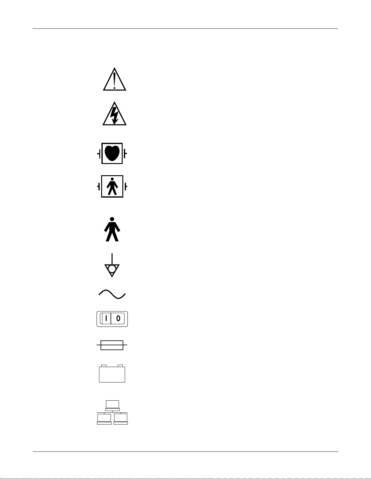
Equipment Symbols
Some of the following symbols appear on the equipment.
ATTENTION: Consult accompanying documents before using the
equipment.
In Europe, this symbol means dangerous or high voltage. In the United
States, this symbol represents the caution notice below:
To reduce the risk of electric shock, do NOT remove cover (or back).
Refer servicing to qualified personnel.
Defibrillator-proof type CF equipment; type CF equipment is
specifically designed for applications where a conductive connection
directly to the heart is established. The paddles indicate the equipment
is defibrillator proof.
Defibrillator-proof type BF equipment; type BF equipment is suitable
for intentional external and internal application to the patient,
excluding direct cardiac application. Type BF equipment is type B
equipment with an F-type isolated (floating) part. The paddles indicate
the equipment is defibrillator proof.
Type B equipment; type B equipment is suitable for intentional
external and internal application to the patient, excluding direct
cardiac application.
Equipotentiality
Alternating current (AC)
Power;
Fuse
Battery
Indicates the Ethernet connection for the monitor.
I = ON; O= OFF
1-6 Dash 3000/4000 Patient Monitor Revision A
2000966-035
Page 15

INTRODUCTION: Safety Information
PRESS
814A
815A
816A
817A
818A
Press to open.
Power
Graph Go/Stop
NBP Go/Stop
Function
Silence Alarm
Classified by Underwriters Laboratories Inc. with respect to electric
shock, fire, mechanical and other specified hazards, only in accordance
with UL 2601-1, CAN/CSA C22.2 No. 601.1, IEC 60601-1, and, if
required, IEC 60601-2-27, IEC 60601-2-30, IEC 60601-2-34, IEC 606011-1.
Revision A Dash 3000/4000 Patient Monitor 1-7
2000966-035
Page 16

INTRODUCTION: Service Information
Service Information
Service Requirements
Equipment Identification
Follow the service requirements listed below.
• Refer equipment servicing to GE Medical Systems Information
Technologies’ authorized service personnel only.
• Any unauthorized attempt to repair equipment under warranty voids
that warranty.
• It is the user’s responsibility to report the need for service to GE
Medical Systems Information Technologies or to one of their
authorized agents.
• Failure on the part of the responsible individual, hospital, or
institution using this equipment to implement a satisfactory
maintenance schedule may cause undue equipment failure and
possible health hazards.
• Regular maintenance, irrespective of usage, is essential to ensure
that the equipment will always be functional when required.
Every GE Medical Systems Information Technologies device has a unique
serial number for identification. A sample of the information found on a
serial number label is shown below.
D 0 XX 0005 G XX
Month
Manufactured
A = January
B = February
C = March
D = April
E = May
F = June
G = July
H = August
J = September
K = October
L = November
M = December
Year
Manufactured
0 = 2000
1 = 2001
2 = 2002
(and so on)
Product Code
Two-character
product
descriptor
Product
Sequence
Number
Manufacturing
number (of total
units
manufactured)
Division
F = Cardiology
G = Monitoring
Device Characteristics
One or two letters that
further describe the unit,
for example:
P = prototype not
conforming to marketing
specification
R = refurbished equipment
S = special product
documented under Specials
part numbers
U = upgraded unit
1-8 Dash 3000/4000 Patient Monitor Revision A
2000966-035
Page 17

2 EQUIPMENT OVERVIEW
Revision A Dash 3000/4000 Patient Monitor 2-1
2000966-035
Page 18

For your notes
EQUIPMENT OVERVI EW:
2-2 Dash 3000/4000 Patient Monitor Revision A
2000966-035
Page 19
Components
EQUIPMENT OVERVIEW: Components
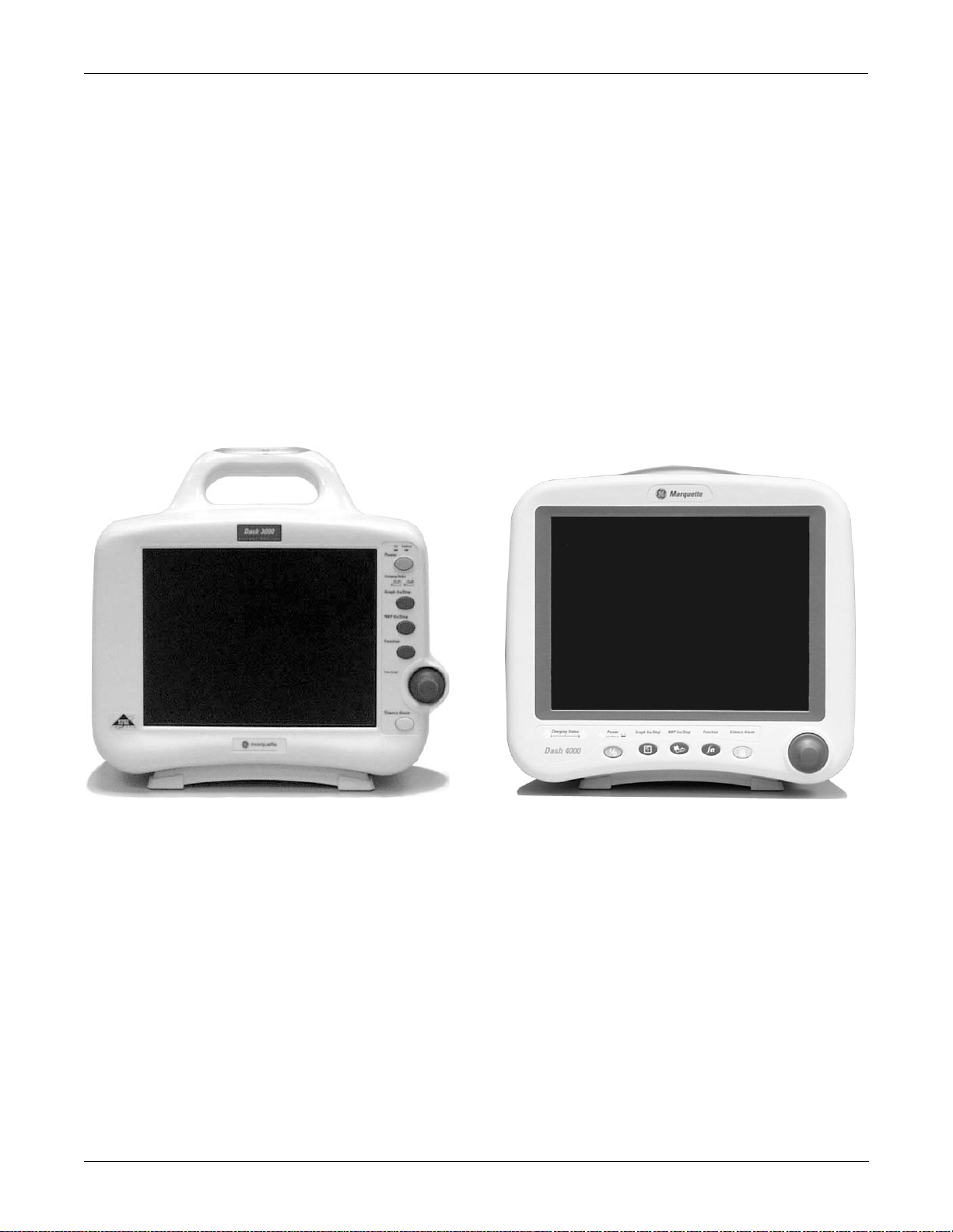
The Monitoring System
The Patient Monitor
The Dash 3000/4000 patient monitor can function by itself with a built-in
writer, or it can be cabled in with the Unity Network via Ethernet.
Optional components are, if using Wireless LAN or cabled to Ethernet, a
Centralscope central station and the Clinical Information Center.
This device is designed to monitor a fixed set of parameters including
ECG, noninvasive blood pressure, impedance respiration, SpO2, and
temperature. Invasive pressure and EtCO2 are optional features.
Additional specialized features include cardiac output, cardiac
calculations, pulmonary calculations, dose calculations, PA wedge (PA
wedge is only available with the invasive pressure option), and SAM
module interface.
001A
Dash 3000 Monitor
Revision A Dash 3000/4000 Patient Monitor 2-3
2000966-035
Dash 4000 Monitor
051A
Page 20
EQUIPMENT OVERVIEW: Components
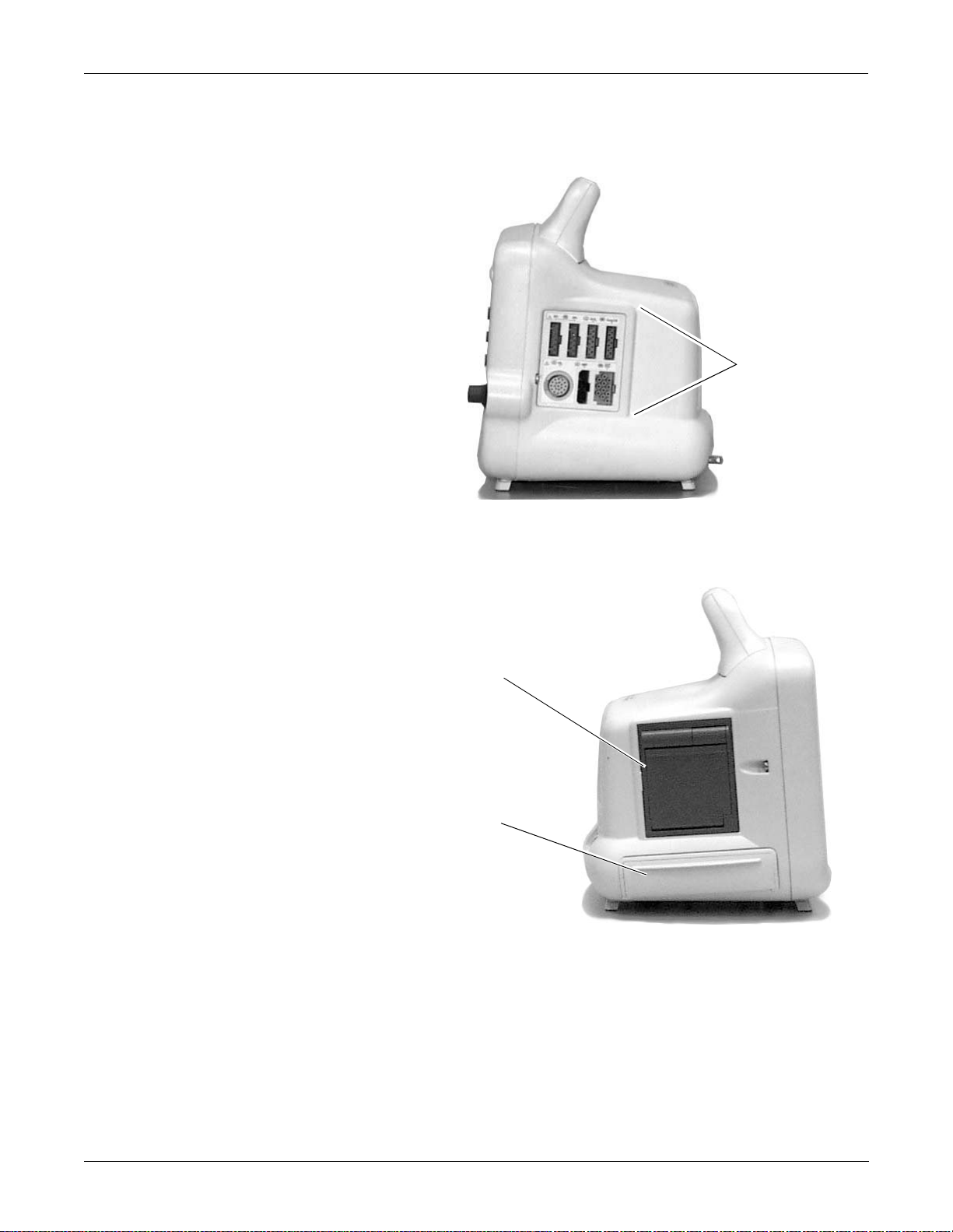
Right Side View
Left Side View
All of the patient cable connectors are located on the right side of the
monitor. A Trim Knob control provides single control operation of
virtually all monitor functions.
Patient Cable
Connectors
002A
On the left of the monitor, you can find the built-in writer and the
battery compartment.
Optional Built-in Writer—
The built-in, 4 channel
writer is located in the
center of the left side of the
monitor .
Battery Compartment—
The battery packs are
located in this
compartment.
003A
2-4 Dash 3000/4000 Patient Monitor Revision A
2000966-035
Page 21
EQUIPMENT OVERVIEW: Components
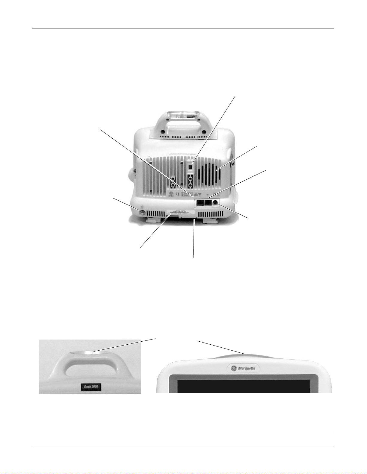
Back Vie w
Network Connector—A cable
can be connected to this port
for monitors used in patient
monitoring network
configurations.
Equipotential Terminal—For
measurements in or near the heart
we recommend connecting the
monitor to the potential
equalization system. U se the
green and yellow potential
equalization cable and connect it
to this pin.
AC Power Connector
On the back of the monitor you will find all connectors for equipment and
network.
Line V oltage Selector—This s elector
is factory set to match the line
voltage and frequency rating for
your country.
Audible Alarm Enunciator—The
internal speaker provides sound
for audible alarms. For better
sound quality do not block
speaker.
Aux Port—Used for
RAC 2A and software
updates.
Defib Sync Connector—Provides
ECG analog output signals to
004A
Peripheral Expansion Port
user-supplied equipment. A 5volt, 2-millisecond artificial pacer
spike is added to the analog
output when PACE is on and
detection occurs.
Optional Alarm Indicator
An optional alarm indicator can be built into the handle of the Dash 3000
monitor or into the display bezel of the Dash 4000 monitor. When
activated, the LED indicator flashes red for CRISIS and WARNING
patient status alarms and yellow for all other alarms.
Alarm Indicator
Dash 3000 Monitor
Revision A Dash 3000/4000 Patient Monitor 2-5
2000966-035
Dash 4000 Monitor
052A
Page 22
EQUIPMENT OVERVIEW: Components
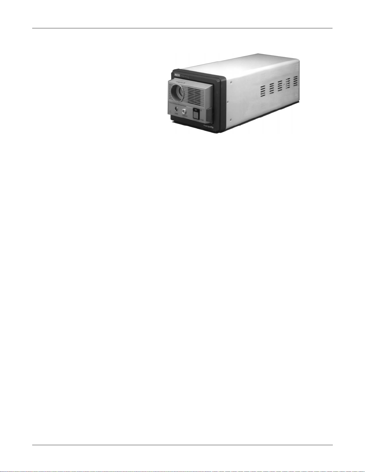
Optional RAC 2A Module Housing
The RAC 2A module housing currently supports the SAM module.
006A
An integral power supply is used to run the RAC 2A and support the
needed voltages.
2-6 Dash 3000/4000 Patient Monitor Revision A
2000966-035
Page 23

EQUIPMENT OVERVIEW: Components
Optional Wireless LAN System
Access Points
The flexibility of the GE Medical Systems Information Technologies
Unity Network is increased by using the Wireless LAN system. The
Wireless LAN system allows the user to roam from one access point to
another, maintaining a strong, seamless connection to the Unity
network.
The monitor, with its optional built-in Wireless LAN, functionally
performs the same as a monitor connected directly to the Unity network.
It can be viewed at the central station and by other GE Medical Systems
Information Technologies’ monitors on the network (i.e. Dash 3000/4000,
Eagle 4000, and Solar patient monitors). Monitors with Wireless LAN
sends and receives patient data via the access points of the Unity
network.
NOTE: Wireless patient monitors that are moved from room to room
must have the monitor type configured as Rover or Rover/Combo
monitoring.
To integrate the wireless network with the wired network, one or more
access points are necessary. An access point connects the wireless
monitor to the wired network infrastructure within the building, and
acts as a bridge between the wired and wireless networks. The areas
covered by each access point overlap to insure continuous coverage.
NOTE: The monitor will only work with a Symbol Access Point. The
monitor will not communicate directly with a Wireless LAN
device from Aironet.
050A
Revision A Dash 3000/4000 Patient Monitor 2-7
2000966-035
Page 24

EQUIPMENT OVERVIEW: Technical Specifications
Technical Specifications
Due to continual product innovation, specifications are subject to change
without notice. The following specifications are accurate as of the date of
this publication, and pertain to the Dash 3000/4000 Patient Monitor.
Performance Specifications
Display
Size:
Type:
Color: Active-Matrix Liquid Crystal Display (LCD)
Resolution: 640 by 480 pixels
Dash 3000:
Dash 4000:
8.4-inch diagonal
10.4-inch diagonal
Controls
Alarms
Number of traces: 6 (maximum)
Number of seconds/trace:
Dash 3000:
Dash 4000:
Sweep speed:
All waveforms 6.25, 12.5 or 25 mm/sec (with erase bar)
Waveform display options: Individual 6 waveforms, individual 3 waveforms, full,
Information window: Displays non-real-time information without obstructing
Display organization: Prioritized by parameter
Standard: Trim Knob control plus 5 hard keys: Power, NBP Go/
Categories: Patient Status and System Status
4.9 at 25 mm/sec
5.9 at 25 mm/sec
and full grid modes
the display of real-time information
Stop, Function, Silence Alarm, and Graph Go/Stop
Priorities: 4 levels — Crisis, Warning, Advisory, and Message
Notification: Audible and visual
Setting: Default and individual
Silencing: 1 minute, current alarm only
2-8 Dash 3000/4000 Patient Monitor Revision A
2000966-035
Page 25

ECG
EQUIPMENT OVERVIEW: Technical Specifications
Pause: 5 minutes (adult); 3 minutes (neonatal); 5, 15 minutes,
permanent (OR mode)
Volume: Default 70%, 70 dB measured at 1 meter
5 Leadwire cable: I, II, III, V, aVR, aVL, and aVF
10 Leadwire cable (12SL option): V2, V3, V4, V5 and V6
Leads analyzed simultaneously: I, II, III, and V (multi-lead mode)
Lead fail: Identifies failed lead
Alarms: User-selectable upper and lower heart rate limits
Input specifications:
Voltage range:
Signal width:
Heart rate range:
Accuracy:
Input impedance:
Common mode:
Differential:
Common mode rejection:
±0.5 mV to ±5 mV
40 ms to 120 ms (Q to S)
30 to 300 BPM
±1% or ±1 BPM, whichever is greater
>10 M
Ω
at 50/60 Hz
>2.5 M
Ω
from dc to 60 Hz
90dB minimum at 50 Hz or 60 Hz
Output specifications:
Frequency response:
Display:
Diagnostic:
Monitoring:
Moderate:
Maximum:
Paper Recorder:
Diagnostic:
Monitoring:
Moderate:
Maximum:
Linearity deviation:
Noise:
ST segment measurement:
Measurement point:
Measurement range:
Measurement accuracy:
Pacemaker detection/rejection:
Input voltage range:
Input pulse width:
Rise time:
Over/under shoot:
Baseline drift:
0.05 to 40 Hz
0.05 to 40 Hz
0.05 to 25 Hz
5 to 25 Hz
0.05 to 100 Hz
0.05 to 40 Hz
0.05 to 25 Hz
5 to 25 Hz
±3% (maximum)
<30 µV (referred to input)
Adjustable from 0 to 120 ms past the J-point
(default: 60 ms adult, 30 ms neonatal)
–12.0 to +12.0 mm
±10% or 0.5 mm, whichever is greater
±2 mV to ±700 mV
0.1 ms to 2 ms
10 µs to 100 µs
2 mV (max)
<0.5 mV/hour with a ±700-mV, 2-ms pacemaker pulse
applied
Revision A Dash 3000/4000 Patient Monitor 2-9
2000966-035
Page 26

Invasive Blood Pressure (BP)
EQUIPMENT OVERVIEW: Technical Specifications
Number of channels: 2
Transducer sites: Arterial (ART), femoral artery (FEM), pulmonary artery
(PA), central venous (CVP), right atrial (RA), left atrial
(LA), intracranial (ICP), and special (SP)
In neonatal mode: umbilical artery catheter (UAC) and
umbilical venous catheter (UVC)
Transducer requirements:
Excitation voltage:
Transducer output:
Input specifications:
Range:
Offset:
Output specifications:
Frequency response:
Zero balance range:
Zero balance accuracy:
Zero balance drift:
Accuracy:
Alarms:
5.0 Vdc ±0.1%
5 µV/V/mmHg
–25 mmHg to 300 mmHg
±150 mmHg
dc to 50 Hz
±150 mmHg
±1 mmHg
±1 mmHg over 24 hours
±2% or ±1 mmHg, whichever is greater (exclusive of
transducer)
User-selectable upper and lower limits for systolic,
diastolic, and mean pressures
2-10 Dash 3000/4000 Patient Monitor Revision A
2000966-035
Page 27

EQUIPMENT OVERVIEW: Technical Specifications
Noninvasive Blood Pressure (NBP)
Measurement technique: Oscillometric
Displayed parameters: Systolic, diastolic, and mean pressures, pulse rate, time
of last measurement
Measurement modes: Manual, auto, and stat in adult and OR modes; manual
and auto in neonatal mode
NBP pressure range:
Systolic pressure range
Adult:
Pediatric:
Neonatal:
Diastolic pressure range
Adult:
Pediatric:
Neonatal:
Mean pressure range
Adult:
Pediatric:
Neonatal:
30 to 275 mmHg
30 to 235 mmHg
30 to 135 mmHg
10 to 220 mmHg
10 to 220 mmHg
10 to 110 mmHg
20 to 260 mmHg
20 to 260 mmHg
20 to 125 mmHg
Cuff pressure range:
Adult:
Pediatric:
Neonatal:
Pressure accuracy:
Static:
Clinical:
Heart rate detection: 30 to 200 beats per minute
Total cycle time: 20 to 40 seconds typical (dependent on heart rate and
Automatic cycle times: 0 to 8 hours
Auto zero: Zero pressure reference prior to each cuff inflation
Tubing length:
Adult:
Neonatal:
Automatic cuff deflation: Cycle time exceeding 3 minutes (90 seconds neonatal),
Cuff sizes:
Disposable:
Reusable:
0 to 275 mmHg
0 to 235 mmHg
0 to 135 mmHg
±2% or ±3 mmHg, whichever is greater
±5 mmHg average error
8 mmHg standard deviation
motion artifact)
12 feet
8 feet
power off, or cuff pressure exceeds 294 mmHg (±6
mmHg) adult, 147 mmHg (±3 mmHg) neonatal
Large adult, adult, small adult, pediatric, small pediatric,
and infant
Thigh, large adult, adult, child, and infant
Alarms: User-selectable upper and lower limits for systolic,
diastolic, and mean pressures
Revision A Dash 3000/4000 Patient Monitor 2-11
2000966-035
Page 28

Pulse Oximetry (SPO2)
EQUIPMENT OVERVIEW: Technical Specifications
Parameters monitored: Arterial oxygen saturation (SpO2) and peripheral pulse
rate (PPR)
SpO2 range: 50 - 100%
PPR range: 30 - 300 beats per minute
Cardiac Output (CO)
Accuracy:
SpO2:
PPR:
Alarms: User-selectable upper and lower limits for SpO2 and
Availability: Included in 7020 and 7025 software packages. Not
Input specifications:
Probe type:
Catheter manufacturers:
Catheter sizes:
Abbott catheter sizes:
Arrow catheter sizes:
Baxter catheter sizes:
Ohmeda catheter sizes:
Other catheter sizes:
Injectate volume:
Actual accuracy depends on probe. Please reference
manufacturer’s specifications.
± 2% (70 - 100% SpO2) ±1 standard deviation
± 3% (50 - 69% SpO2) ±1 standard deviation
± 3 beats per minute
PPR
available in 7015 software package.
In-line or bath probe
Abbott, Arrow, Baxter, Ohmeda, or other
5.5F (75 cm), 7F (85 cm), 7.5F (110 cm), and
8F (110 cm)
5, 6, 7, or 7.5F
5, 6, 7, 7.5 or 8F
5, 7, or 7.5F
Cardiac coefficient entered manually
3, 5, or 10 cc
Output specifications:
Parameters displayed:
Range:
Cardiac output:
Blood temperature:
Injectate temperature:
Accuracy:
Cardiac output:
Blood temperature:
Injectate temperature:
Frequency response:
2-12 Dash 3000/4000 Patient Monitor Revision A
2000966-035
Cardiac output, blood temperature, injectate
temperature, trial number
0.2 - 15 liters per minute
30 - 42°C
0 - 30°C
±5% (liters of blood/min)
±0.2°C
±0.3°C
dc to 15 Hz ±2 Hz
Page 29

EQUIPMENT OVERVIEW: Technical Specifications
Respiration
Temperature (TEMP)
Measurement technique: Impedance variation detection
Range:
Respiration rate:
Base impedance:
Detection sensitivity:
Accuracy:
Respiration rate ±1 BrPM
Waveform display bandwidth: 0.1 to 1.8 Hz (–3 dB)
Alarms: User-selectable upper and lower respiration rate limits,
Number of channels: 2
Input specifications:
Probe type:
Temperature range:
Resolution:
0 - 200 breaths per minute
100 - 1000
0.4 to 10
and user-selectable apnea limit
YSI Series 400 or 700 thermistor (determined by input
cable)
0°C to 45°C (32°F to 113°F)
±0.1°C
Ω
at 52.6 kHz excitation frequency
Ω
variation
Carbon Dioxide (CO2)
Output specifications:
Parameters displayed:
Accuracy:
Alarms:
Information displayed: Inspired and expi red car bon diox ide co ncen tra tion s in %,
Measurement technique: Non-dispersive infrared absorption, dual wavelength
Sensor type: Novametrix Medical Systems’ Capnostat III
Patient interface: Compatible with Novametrix Medical Systems’
Airway adaptors
Types:
Dead space/chamber volumes:
Adult reusable:
Adult disposable:
Neonatal:
T1, T2
(independent of source)
±0.1°C for YSI series 400 probes;
±0.3°C for YSI series 700 probes
User-selectable upper and lower limits for T1, T2
mmHg or kPa, respiration rate, continuous CO2 wavef orm
ratiometric
Capnogard monitoring product
Adult reusable (standard), adult disposable, neonatal
<5 cc
<5 cc
<0.5 cc
Revision A Dash 3000/4000 Patient Monitor 2-13
2000966-035
Page 30

EQUIPMENT OVERVIEW: Technical Specifications
CO2 measurement specifications:
Measurement range:
Pi CO2/Fi CO2:
Pe CO2/Fe CO2:
RR:
Accuracy:
Display update interval:
CO2 waveform sweep speed:
CO2 averaging:
CO2 measurement stability:
Resolution:
Noise:
0 to 100 mmHg/0 to 13%
0 to 100 mmHg/0 to 13%
0 to 120 breaths/min
±5% of reading or ±2 mmHg, whichever is greater
2 sec
Selectable 6.25, 12.5, or 25 mm/sec
Selectable from single breath, 10 sec, or 20 sec
Accuracy maintained over 8 hours
1 mmHg
2% of reading or 0.5 mmHg (maximum), whichever is
greater
60 Hz interference:
<0.5 mmHg at 38 mmHg
Step response time:
Adult:
Neonatal
<60 ms (10-90%)
<50 ms (10-90%)
Interference:
N2O gas:
±5% of reading or ±2 mmHg (maximum), whichever is
greater, with N2O compensation enabled
O2 gas:
±5% of reading or ±2 mmHg (maximum), whichever is
greater, with O2 compensation enabled
Barometric pressure:
Water vapor:
±2 mmHg (maximum) from 500 to 800 mmHg
±1.5% of reading or ±0.5 mmHg (maximum),
whichever is greater
Anesthetic agent:
±0.5 mmHg (maximum) for concentration of no more
than 5% of halogenated agents
Airway adapter variability:
±3% of reading or ±1.5 mmHg (maximum), whichever
is greater, with same or different adapter; not applicable
after adapter zero
Warm-up time:
Less than 15 seconds to initial CO2 indication, full
specification within 120 seconds; waveform immediate
upon power up
Calibration:
Factory settings:
Factory calibration settings stored in nonvolatile
memory within the sensor; 15 second adaptor
calibration when switching airway types
Verification:
Zero and span performance check with on-cable verifier
Respiration rate specifications:
Range (for 5% step size):
Accuracy:
Resolution:
0-120 breaths per minute
±1 breath per minute
±1 breath per minute
Barometric pressure sensor
specifications:
Range:
Accuracy:
425 to 817 mmHg (56 to 109 kPa)
±25 mmHg
Alarms: User-selectable upper and lower limits for CO2 and RR.
2-14 Dash 3000/4000 Patient Monitor Revision A
2000966-035
Page 31

Analog Output
Defibrillator Synchronization Pulse
EQUIPMENT OVERVIEW: Technical Specifications
ECG:
Gain:
DC offset:
Noise:
Frequency response:
Time delay:
Blood pressure:
Gain:
DC offset:
Noise:
Frequency response:
Time delay:
1 V/mV ±10%
±100 mV (max)
<5 mVp-p (0-300 Hz)
0.05 Hz to 100 Hz +7/–0 Hz
40 ms monitoring filter, 35 ms diagnostic filter
10 mV/mmHg ±2%
±20 mV (max)
<5 mVp-p (0-300 Hz)
dc to 50 Hz +2/–0 Hz
40 Hz filter, 37 ms
Marker out:
Time delay:
Amplitude (selectable in Service
menu):
+5 V selection:
+12 V selection:
Pulse width:
Output impedance:
Current limit:
Marker in:
Input threshold:
Input hysteresis:
Maximum input voltage:
Input impedance:
Pulse width:
35 ms (maximum), R-wave peak to leading edge of
pulse.
3.5 V (min) at 1 mA sourcing; 0.5 V (max) at 5 mA
sinking.
11.0 V (min) at 1 mA sourcing; 0.75 V (max) at 5 mA
sinking.
10 ms ±10% or 100 ms ±10% (selectable in Service
menu).
50
Ω
nominal
15 mA nominal, both sourcing and sinking.
V
= ±2.5 V (min); VIL = ±1.5 V (max)
IH
650 mV typical
±30 V (with respect to ground on pin 3)
10 k
Ω
(min) for -25 V < VIN < 25 V
1.0 ms (min), VIN > 2.5 V
Revision A Dash 3000/4000 Patient Monitor 2-15
2000966-035
Page 32

Battery
Paper Recorder
EQUIPMENT OVERVIEW: Technical Specifications
Battery type: Exchangeable Lithium-Ion
Number of batteries: 2
Battery weight: 0.36 kg (0.8 lbs) each
Voltage: 11.1 V (nominal)
Capacity: 3.9 Ah
Charge time: Less than 4 hours each
Run time: 4 to 5 hrs
Method: Thermal dot array
Horizontal resolution: 480 dots/in at 25 mm/sec
Vertical resolution: 200 dots/in
RF Wireless LAN
Number of waveform channels: 4
Paper width: 50 mm (1.97 in)
Paper length: 30 m (100 ft)
Paper speed: 0.1, 0.5, 1, 5, 10, 12.5, 25, and 50 mm/sec (± 2%)
Transmission technique: Frequency hopping spread spectrum
Frequency: Country dependent, specific settings received from
access point. Within 2400 to 2500 MHZ range.
Frequency hopping
characteristics:
Radio data rate: 1 and 2 Mbps
Radio output power: 160 mW (including antenna gain)
1 Mbps range: Open environment: over 850 ft. (260)
2 Mbps range: Open environment: over 425 ft. (130)
Country dependent, specific settings received from
access point. IEEE 802.11 compliant
Typical hospital environment: between 150 and 200 ft.
(45 to 60 m)
Typical hospital environment: between 100 and 150 ft.
(30 to 45 m)
Modulation: Binary GFSK
Applicable standards: US: FCC Part 15 Class B
Europe: ETS 300 328 and ETS 300 826
2-16 Dash 3000/4000 Patient Monitor Revision A
2000966-035
Page 33

Environmental Specifications
EQUIPMENT OVERVIEW: Technical Specifications
NOTE: The system may not meet its performance specifications if
stored or used outside the manufaturer’s specified temperature
and humidity range.
Power requirements:
90-132VAC
190-264 VAC
Power consumption: 75 watts (fully loaded)
Cooling: Convection
Heat dissipation: 240 Btu/hr (max)
Battery operation time:
General: Battery age will affect operating time.
Operating conditions:
Ambient temperature:
While charging batteries:
Capnostat III sensor
Relative humidity:
Vibration:
Altitude:
50/60 Hz 2.0A
50/60 Hz 1.0A
0 to 40°C (32 to 104°F)
0 to 35°C (32 to 95°F)
10° to 40° C (50° to 104°F)
5 to 95% at 40°C
MIL-STD 810E, Method 514.4, Category 1
-610 to 4, 570 m (-2,000 to 15,000 ft)
Physical Specifications
Storage conditions (Do not
exceed):
Maximum:
Minimum:
CO2 Sensor:
Batteries:
Equipment Type: Portable per IEC 60601-1
Height:
Dash 3000
Dash 4000
Width:
Dash 3000
Dash 4000
Depth:
Dash 3000
Dash 4000
Weight (without batteries)
Dash 3000
Dash 4000
70°C (158°F) at 95% relative humidity
–40°C (–40°F) at 15% relative humidity
–30 to 65°C (–22 to 149°F)
–20 to 60°C (–4 to 140°F)
26 cm (10.25 inches)
27.38 cm (10.78 inches)
28 cm (11.0 inches)
29.26 cm (11.5 inches)
20 cm (8 inches)
24.26 cm (9.55 inches)
5.08 kg (11.2 lbs)
5.53 kg (12.2 lbs)
Revision A Dash 3000/4000 Patient Monitor 2-17
2000966-035
Page 34

Certification
Safety
EQUIPMENT OVERVIEW: Technical Specifications
UL 2601-1 classified.
UL classified for CAN/CSA C22.2 No. 601.1
IEC 60601-1 and EN 60601-1 Certified
CE marking for Council Directive 93/42/EEC concerning medical devices
Radio and Telecommunication Terminal Equipment Directive
Electromagnetic Compatibility Compliance (EMC)
The Dash 3000/4000 system meets the requirements of EN 60601-1-2
(1993–04) Medical Electrical Equipment, Part 1: General Requirements
for Safety, 2. Collateral Standard: Electromagnetic compatibility—
Requirements and tests.
Exceptions
SpO2 Parameter — EN 60601-1-2 clause 36.202.1—IMMUNITY:
Radiated Immunity:
• The level of compliance is 1 volt per meter. If operating under the
conditions defined in EMC Standard EN60601-1-2 (Radiated
Immunity 3 volts per meter), field strength above 1 volt per meter
may cause waveform distortions and erroneous numeric data at
various electromagnetic interference (EMI) frequencies.
CO2 Parameter — EN 60601-1-2 clause 36.202.1—IMMUNITY:
Radiated Immunity:
• ‘The level of compliance is 1 volt per meter. If operating under the
conditions defined in EMC Standard EN60601-1-2 (Radiated
Immunity 3 volts per meter), field strength above 1 volt per meter
may cause waveform distortions and erroneous numeric data at
various electromagnetic interference (EMI) frequencies.
Recommendations
Review the AAMI EMC Committee technical information report (TIR-18)
titled Guidance on electromagnetic compatibility of medical devices for
clinical/biomedical engineers - Part 1: Radiated radio-frequency
electromagnetic energy. This TIR provides a means to evaluate and
manage the EMI environment in the hospital.
The following actions can be taken:
• managing (increasing) distance between sources of EMI and
susceptible devices.
• managing (removing) devices that are highly susceptible to EMI
• lower power from internal EMI sources under hospital control (i.e.
paging systems)
• labeling devices susceptible to EMI
• educate staff (nurses and doctors) to be aware of, and to recognize,
2-18 Dash 3000/4000 Patient Monitor Revision A
2000966-035
Page 35

Warranty
EQUIPMENT OVERVIEW: Technical Specifications
potential EMI related problems
Standard: One year. Other options are available. Contact your
sales representative for more information.
Revision A Dash 3000/4000 Patient Monitor 2-19
2000966-035
Page 36

EQUIPMENT OVERVIEW: Technical Specifications
2-20 Dash 3000/4000 Patient Monitor Revision A
2000966-035
Page 37

3 INSTALLATION
Revision A Dash 3000/4000 Patient Monitor 3-1
2000966-035
Page 38

For your notes
INSTALLATION:
3-2 Dash 3000/4000 Patient Monitor Revision A
2000966-035
Page 39

Connections
INSTALLATION: Connections
Back Panel Connections
ETHERNET
On the back of the monitor you will find all connectors for equipment and
network.
AC Power Connector
Aux Port
Defib Sync Connector
004A
Peripheral Expansion Port
ETHERNET
RAC 2A Housing Connectors
The ETHERNET connector provides an ANSI/IEEE 802.3 10BaseT
Ethernet standard interface to the Unity Network.
The RAC 2A module housing connects to the monitor via a standard
category 5 patch cable (PN 418335-002) which plugs into the AUX port
on the monitor and to the Auto Port on the back of the RAC 2A module
housing.
The RAC 2A module housing does not have an Analog Output connector.
Power Switch
AC Power
Auto Port to the
monitor’s Aux Port
Async Comm
007A
Revision A Dash 3000/4000 Patient Monitor 3-3
2000966-035
Page 40

INSTALLATION: Connections
Defib Sync
AC Pow er
The connector provides ECG analog output signals to user-supplied
equipment.
CAUTION
Equipment damage. Connect all peripheral equipment
before plugging the power cord into an AC outlet.
Otherwise, connectors may be damaged.
Use this connector to apply power to the monitor. The monitor will be
powered at all times when using AC power (there is no AC power switch).
The monitor is preset at the factory for a specific AC voltage. Before
applying power, be sure the power requirements match your power
supply. Refer to the label on the back of the unit for the voltage and
current requirements.
3-4 Dash 3000/4000 Patient Monitor Revision A
2000966-035
Page 41

INSTALLATION: Connections
Front Panel Indicators
AC/ Battery Power
Indicators
Battery A and B Charge
Status Indicators
009A
Dash 3000 Monitor’s Front Panel
AC Power Indicator
Battery Power Indicator
Power and battery indicators are located on the front panel of the
monitor.
Battery A and Battery B Charge S tatus
Indicators
Dash 4000 Monitor’s Front Panel
The indicator illuminates green when AC power is applied to the
monitor. The indicator is not illuminated when the monitor is not
powered.
The indicator illuminates yellow when the monitor is battery powered.
The indicator is not illuminated when the monitor is not powered or
when AC power is applied.
AC/Battery Power
Indicator
053A
Battery Charging/Ready Indicators
Power Up
An icon for each battery pack indicates its charging status. The battery
icon illuminates yellow when the respective battery is being charged. If
both batteries are present and require charging, then both icons will
illuminate even though they will be charged sequentially. The battery
icon illuminates green when the respective battery is fully charged.
When the monitor is operating under battery power the battery icons will
not be illuminated. The icons are also not illuminated when the
respective battery is either not being charged, not installed, or has failed.
NOTE
No specific information is given to distinguish a failed
battery pack condition from a condition where the
battery is not installed or is not being charged.
After making all connections, plug the power cord into an AC wall outlet.
When all cables are properly connected, press the power button to turn
the monitor on. All four front panel indicators will illuminate until the
power-up sequence is complete. After approximately 10 seconds you
should see a display on the screen.
Revision A Dash 3000/4000 Patient Monitor 3-5
2000966-035
Page 42

INSTALLATION: Ethernet Communication
Ethernet Communication
Overview
Twisted Pair
Concentrator
Ethernet is a local area network used as the main link of the GE Medical
Systems Information Technologies’ Unity network, a comprehensive
information communication system. The Unity network offers the high
rate of communication of 10 megabits per second. The Ethernet
connector connects to an Ethernet transceiver directly or via a
transceiver cable. This local area network links all patient monitors,
central stations, and other GE Medical Systems Information
Technologies’ equipment throughout the hospital. Depending on the
construction of the hospital, thick-net, thin-net, or twisted pair cabling is
used.
Twisted pair is the most popular cabling because it is easy to install and
flexible to work with. It uses the star topology with a concentrator as the
hub of the segment. Each of the network devices is connected directly to
the concentrator so longer lengths of cable are required. A maximum of
100 meters or 328 feet is the longest length of twisted pair cable used.
The number of devices is limited to the amount of connectors at the
concentrator.
The concentrator is simply a transceiver that passes all network data
between any two branches in the LAN. Note that the concentrator passes
all network data between the two branches, regardless of whether or not
one node is sending data to another node on the same branch.
To implement the star topology, each network device is connected to a
concentrator. The concentrator functions as a central hub and simply
passes all network data between each network device in the star
segment. Typically, the concentrator supports 8 to 12 network devices
and may be linked to other concentrators to form larger networks.
3-6 Dash 3000/4000 Patient Monitor Revision A
2000966-035
Page 43

INSTALLATION: Ethernet Communication
Node
Segment and Branch
Each network device or node is assigned an address number and requires
a transceiver to interface between the network device and the network.
For thick-net and thin-net cabling a transceiver and a serial drop cable
connects to the main trunk. The serial drop cable is sometimes referred
to as an AUI (attachment unit interface) transceiver cable. For twisted
pair cabling, the transceiver to connected directly to the network device.
Some Ethernet systems are comprised of smaller, stand-alone Ethernet
systems (called branches or segments) that are connected by bridges,
concentrators, or repeaters. Many nodes on the Ethernet network may be
serviced by one segment or branch. Each segment may support many
patient monitors, central stations, and auxiliary devices.
For example, one segment may connect all the patient monitors and
central stations in the ICU (Intensive Care Unit) and another may
connect the monitoring system in the CCU (Critical Care Unit). Each
segment could be a fully-functioning stand-alone system if they were not
connected to each other. However, with a bridge or repeater to connect
the ICU (one segment) with the CCU (the other segment), information
can pass between any of the nodes (patient monitors and central
stations) on either branch similar to a patient transfer from one unit to
another.
A section is a single length of twisted pair cable with a RJ-45 connector
on each end. A section goes from one twisted pair transceiver to the
concentrator. A segment is comprised of all the sections of twisted pair
cable connected in a star formation to one concentrator.
Repeater
A repeater is used to extend the length of cabling when the distance
required exceeds the length of the cable specifications. It is simply a
transceiver that passes all network data between any two segments.
Note that the repeater passes all network data between the two
segments, regardless of whether or not the one node is sending data to
another node on the same segment.
Revision A Dash 3000/4000 Patient Monitor 3-7
2000966-035
Page 44

INSTALLATION: Ethernet Communication
Bridge
Twisted Pair Cabling (10BaseT)
A bridge is more selective than a repeater with the data that it passes
between segments. It also acts as a transceiver between two segments,
but it only passes signals if a node on one of the segments is attempting
to communicate with a node on the other segment. Since the majority of
communication on the network occurs within a single segment, the
bridge does not pass all of the data from one segment to the other. This
lowers the amount of data traffic passing between segments, and makes
the network more efficient than a system that is connected with
repeaters.
Twisted pair is an IEEE 802.3 local area network that uses flat and
small diameter cable containing four pairs of twisted wires to connect
devices. Twisted pair operates at the same speed as thin-net and thicknet (10 megabits/second), but the cable distances extended up to 100
meters (328 feet).
A twisted pair transceiver passes data back and forth between the
network device and the LAN. It is attached directly to the network device
at the at the 15-pin D-type connector. The twisted pair cable is connected
from the RJ-45 connector at the transceiver and the RJ-45 connector at
the concentrator.
NOTE: Some devices (like Octacomm/Solar 8000M patient monitor)
have 10BaseT standard meaning that the RJ-45 connector is
part of the product and the twisted pair transceiver is not
required.
Symbol PC Card (Wireless LAN)
The Symbol PC card, installed in the monitor, uses a 2.4 GHz frequency
band and a Frequency Hopping spread spectrum (FHSS). The Frequency
Hopping spread spectrum meets IEEE 802.11 standards.
Two diversity antennas, installed in the handle of the monitor, radiates
the RF energy through the air to a Symbol Access Point. The Symbol
Access Point also uses a 2.4 GHz frequency band and the Frequency
Hopping spread spectrum.
NOTE: Refer to the Wireless LAN (Symbol Access Point) Installation
and Service Manual for detailed information on the Symbol
Access point.
NOTE: The following is required for the monitor to roam from access
point to access point while maintaining Wireless LAN
communication with the Unity Network.
• Installation of the RF LAN (Wireless LAN) option.
• Configuration and verification of the monitor’s RF LAN
operation.
• Activation of the RF LAN by disconnecting the monitor’s
Ethernet cable.
3-8 Dash 3000/4000 Patient Monitor Revision A
2000966-035
Page 45

4 MAINTENANCE
Revision A Dash 3000/4000 Patient Monitor 4-1
2000966-035
Page 46

For your notes
MAINTENANCE:
4-2 Dash 3000/4000 Patient Monitor Revision A
2000966-035
Page 47

MAINTENANCE: Maintenance Schedule
Maintenance Schedule
Manufacturer Recommendations
To ensure the monitor is always functional when required, qualified
service personnel should perform the following regular maintenance.
• Visual Inspection: Perform a visual inspection upon receipt of the
equipment, every 12 months thereafter, and prior to servicing the
unit.
• Cleaning: Clean the unit upon receipt of the equipment, every 12
months thereafter, and each time the unit is serviced.
• Conditioning the Batteries: Condition the batteries once every
two months or as needed.
• Calibrating the NBP, BP, ECG, and End-tidal CO2 Software:
Calibrate the software upon receipt of the equipment, every 12
months thereafter, and each time the unit is opened for service.
• Electrical Safety Tests: Perform safety tests upon receipt of the
equipment, every 12 months thereafter, and each time the unit is
serviced.
• Checkout Procedure: Perform the checkout upon receipt of the
equipment, every 12 months thereafter, and each time the unit is
serviced.
• Clearing the Stored Patient Data Memory: Admit and discharge
a test patient every 12 months to clear the monitor’s stored patient
data memory.
Manufacturer Responsibility
CAUTION
Failure on the part of all responsible individuals,
hospitals or institutions, employing the use of this device,
to implement the recommended maintenance schedule
may cause equipment failure. The manufacturer does
not, in any manner, assume the responsibility for
performing the recommended maintenance schedule,
unless an Equipment Maintenance Agreement exists.
The sole responsibility rests with the individuals,
hospitals, or institutions utilizing the device.
Revision A Dash 3000/4000 Patient Monitor 4-3
2000966-035
Page 48

Visual Inspection
MAINTENANCE: Visual Inspection
The monitor and it’s components should be carefully inspected prior to
installation, once every 12 months thereafter and each time the
equipment is serviced.
• Carefully inspect the equipment for physical damage to the case, the
display screen, and the keypad. Do not use the monitor if damage is
determined. Refer damaged equipment to qualified service
personnel.
• Inspect all external connections for loose connectors or frayed cables.
Have any damaged connectors or cables replaced by qualified service
personnel.
• Inspect the display face for marks, scratches, or other damage.
Physical damage to a CRT display face may pose an implosion
hazard. Have the CRT replaced by qualified service personnel if
necessary.
• Safety labels and inscription on the device are clearly legible.
4-4 Dash 3000/4000 Patient Monitor Revision A
2000966-035
Page 49

Cleaning
MAINTENANCE: Cleaning
Cleaning Precautions
Use one of the following approved solutions:
• Cidex solution, or
• Sodium hypochlorite bleach (diluted), or
• Mild soap (diluted)
• Lint-free cloth
• Dust Remover (compressed air)
To avoid damage to the equipment surfaces, never use the following
cleaning agents:
• organic solvents,
• ammonia based solutions,
• acetone solution,
• alcohol based cleaning agents,
• Betadine solution,
• a wax containing a cleaning substance, or
• abrasive cleaning agents.
Cleaning the Display
Exterior Cleaning
To clean the display, follow the recommendations of the display’s
manufacturer. In general you will need to use a soft, clean, lint-free cloth
dampened with a glass cleaner.
CAUTION
To avoid getting liquid into connector openings, do not
spray glass cleaning or general cleaning solutions
directly onto the product’s surface.
Clean the exterior surfaces with a clean, lint-free cloth and one of the
cleaning solutions listed in the table above.
• Wring the excess solution from the cloth. Do not drip any liquid into
open vents, switches, plugs, or connectors.
• Dry the surfaces with a clean cloth or paper towel.
Revision A Dash 3000/4000 Patient Monitor 4-5
2000966-035
Page 50

MAINTENANCE: Cleaning
Cleaning the Print Head
Materials Required
Procedure
PRINTHEAD
PAPER DRIVE
ROLLER
Heavy usage causes debris to build up on the print head. This build can
cause the printed images to appear distorted. It is recommended that
this procedure be performed when necessary, depending on usage.
A nonabrasive material/cloth and isopropyl alcohol are all that are
necessary to perform this procedure.
This procedure should be performed in the order listed.
1. Disconnect the power cord from the mains source.
2. Open the writer door to expose the print head.
3. Remove paper roll.
4. Locate print head shown in figure at left. A flashlight may help
illuminate the print head for closer examination.
5. Wipe print head with alcohol and a nonabrasive material/cotton
swab in an side to side motion. Continue wiping until the cloth/swab
wipes clean.
6. Wipe paper drive roller clean of any bits of paper and debris with
alcohol and a nonabrasive material.
4-6 Dash 3000/4000 Patient Monitor Revision A
2000966-035
Page 51

MAINTENANCE: Battery Maintenance
Battery Maintenance
Charging
Conditioning the Batteries
Frequency Guidelines
The battery is charged whenever the monitor is connected to AC power,
regardless whether the monitor is turned on or turned off.
A battery conditioning cycle occurs when the following has been
completed.
1. The battery is fully charged without interruption.
2. The battery is discharged until the monitor shuts down.
3. The battery is charged until the battery status light turns green in
color.
To maintain useful life, use the following guidelines to condition a
battery:
• Once every two months,
• When the run time of the battery becomes noticeably shorter,
• When the predicted run times become noticeably inaccurate, or
• When the associated battery is requesting a conditioning cycle (i.e.,
the CHECK BATT STATUS error message is displayed in the ECG
waveform area and CONDITION is displayed for BATTERY
QUALITY in the Battery Status information window).
Recommendations
Procedure
Conditioning a battery is best done on an external charger (see
instructions included with the charger). However, a conditioning cycle
can also be run on the monitor.
To condition a battery on the monitor, follow this procedure:
1. Disconnect the monitor from the patient and remove it from service.
2. Insert the battery in need of conditioning in one of the battery slots
in the monitor, and leave the other slot EMPTY.
3. Apply AC power to the monitor and allow the battery to charge
uninterrupted until the Charging Status indicator on the front panel
turns green.
4. Remove AC power and allow the monitor to run from the battery
until it shuts off.
5. Apply AC power again to the monitor and allow the battery to charge
uninterrupted until the Charging Status indicator on the front panel
turns green.
6. This battery is now conditioned and the monitor can be returned to
service.
Revision A Dash 3000/4000 Patient Monitor 4-7
2000966-035
Page 52

MAINTENANCE: Battery Maintenance
Replacing the Batteries
1. Open the battery door. The battery door is on the left side of the
monitor, along the bottom.
2. In the middle is a retainer. Turn this away from the battery you are
replacing.
3. Remove the faulty batteries.
Retainer
4. Replace with a new battery. The monitor uses two exchangeable
lithium-ion batteries. Install the battery with the connection pins
facing down and inserted first.
5. Close the battery cover. The retainer needs to be straight up for the
door to close.
6. Verify that the monitor operates correctly:
• Confirm that the Battery IDs with a battery icon displays in the
lower right corner of the monitor.
• Verify that the Battery LEDS illuminate either green or amber.
Disposal
4-8 Dash 3000/4000 Patient Monitor Revision A
When the battery no longer holds a charge, it should be replaced. The
batteries are recycleable. Remove the old battery from the monitor and
follow your local recycling guidelines.
WARNING
Explosion Hazard. DO NOT incinerate the battery or
store at high temperatures.
2000966-035
Page 53

MAINTENANCE: Electrical Safety Tests
Electrical Safety Tests
General
Recommendations
Electrical safety tests provide a method of determining if potential
electrical health hazards to the patient or operator of the device exist.
These instructions are intended for every component in the system. If the
Tram-rac housing does not have its own power supply, it should remain
connected to the monitor throughout the safety tests.
Record the date and results on the “Maintenance/Repair Log” included at
the end of this chapter.
GE Medical Systems Information Technologies recommends that you
perform all safety tests presented in this chapter:
• upon receipt of the device (monitor and its associated equipment),
• every twelve months thereafter, and
• each time the main enclosure is disassembled or a circuit board is
removed, tested, repaired, or replaced.
CAUTION
Failure to implement a satisfactory maintenance
schedule may cause undue equipment failure and
possible health hazards. Unless you have an Equipment
Maintenance Contract, GE Medical Systems Information
Technologies does not in any manner assume the
responsibility for performing the recommended
maintenance procedures. The sole responsibility rests
with the individual or institution using the equipment.
GE Medical Systems Information Technologies service
personnel may, at their discretion, follow the procedures
provided in this manual as a guide during visits to the
equipment site.
Test Conditions
Revision A Dash 3000/4000 Patient Monitor 4-9
Electrical safety tests may be performed under normal ambient
conditions of temperature, humidity, and pressure.
2000966-035
Page 54

MAINTENANCE: Electrical Safety Tests
Test Equipment
The manufacturer recommended test equipment required to perform
electrical safety tests is listed below. Equivalent equipment may be
substituted as necessary.
Required Tools/Special Equipment
Item Part Number
Leakage Current Tester
120 V (or equivalent)
240 V (or equivalent)
Multimeter –
DALE 600
DALE 600E
4-10 Dash 3000/4000 Patient Monitor Revision A
2000966-035
Page 55

MAINTENANCE: Electrical Safety Tests
Wall Receptacle Test
Ground (Earth) Integrity
Before starting the tests, the wall receptacle from which the monitoring
device will get electrical power must be checked. This test checks the
condition of the wall receptacle to ensure correct results from leakage
tests.
For international wall receptacles, refer to the internal standards
agencies of that particular country. Use a digital multimeter to ensure
the wall receptacle is wired properly.
If other than normal polarity and ground is indicated, corrective action
must be taken before proceeding. The results of the following tests will be
meaningless unless a properly wired wall receptacle is used.
Listed below are two methods for checking the ground (earth) integrity,
“Ground Continuity Test” and “Impedance of Protective Earth
Connection.” These tests determine whether the device's exposed metal
and power inlet's earth (ground) connection has a power ground fault
condition.
Ground Continuity Test
Perform the test method below that is required by your Country/Local
governing safety organization.
Completion of this test is checked by the following steps:
1. Disconnect the DUT (device under test) from the wall receptacle.
2. Connect the negative(-) lead of the ohm meter to the protective earth
terminal (ground pin in power in-let connector) or the protective
earth pin in the MAINS PLUG (ground pin in power cord). Refer to
the US 120Vac power cord figure on the left.
3. Set the Ohm meter to the milliohm (mΩ) range.
4. Connect the positive (+) lead of the Ohm meter to all exposed metal
surfaces on the DUT. If the metal surfaces are anodized or painted
scrape off a small area in a inconspicuous area for the probe to make
contact with the metal.
5. Resistance should read to pass:
• 0.1 ohm or less without power cord
• 0.2 ohms or less with power cord
Revision A Dash 3000/4000 Patient Monitor 4-11
2000966-035
Page 56

MAINTENANCE: Electrical Safety Tests
Impedance of Protective Earth Connection
This test unlike a ground continuity test will also stress the ground
system by using special ground bond testers i.e. Kikusui (model 872 or
TOS 6100) or Associated Research model HYAMP® Jr. Model 3030D.
This test normally is only required as a manufacturing production test to
receive safety agency compliance (i.e. IEC601-1).
Some country agency's do require this test after field equipment repairs
(i.e. Germany's DIN VDE 0751 standards).
Consult your country/local safety agency if in question.
Compliance is checked by the following steps:
1. A current not less than 10A and not exceeding 25A from a current
source with a frequency of 50 or 60 Hz with a no-load voltage not
exceeding 6 V is passed for at least 5 s through the protective earth
terminal or the protective earth pin in the mains plug and each
accessible metal part which could become live in case of failure in
basic insulation.
2. The voltage drop between the parts described is measured and the
impedance determined from the current and voltage drop. It shall not
exceed the values indicated.
for equipment without a power supply cord the impedance between the
protective earth terminal and any accessible metal part which is
protectively earthed shall not exceed 0.1 ohms
For equipment with a power supply cord the impedance between the
protective earth pin in the mains plug and any accessible metal part
which is protectively earthed shall not exceed 0.2 ohms.
When taking this measurement move the unit's power cord around, no
fluctuations in resistance should be observed.
4-12 Dash 3000/4000 Patient Monitor Revision A
2000966-035
Page 57

MAINTENANCE: Electrical Safety Tests
Ground (Earth) Wire Leakage Current Tests
Perform this test to measure current leakage through the ground (earth)
wire of the equipment during normal operation.
1. Set the leakage tester switches as follows:
• Selector knob - 1,
• GND switch - OPEN,
• Polarity switch - NORM,
•Power switch - OFF.
2. Connect the DMM to the METER jacks on the leakage tester. Set the
DMM to measure AC millivolts.
3. Connect the power cord of the device under test to the power
receptacle on the rear of the leakage tester.
NOTE: The device under test is to be tested at its normal operating
voltage.
4. Set the leakage tester power switch to ON.
5. Set the power switch of the device under test to ON.
6. Read the current leakage indicated on DMM. If the reading is greater
than the appropriate specification below, the device under test fails
and should be repaired and tested again.
• 300 microamperes (0.3 volts on the DMM), and the device under
test is powered from 100-120 V/50-60 Hz
• 300 µA (0.3 volts on the DMM), and the device under test is
powered from a centered-tapped 200-240 V/50-60 Hz, single
phase circuit
• 500 µA (0.5 volts on the DMM), and the device under test is
powered from a non-center-tapped, 200-240 V/50-60 Hz, singlephase circuit
NOTE: Center-tapped and non-center-tapped circuits produce different
leakage currents and the UL and IEC limits are different.
Revision A Dash 3000/4000 Patient Monitor 4-13
2000966-035
Page 58

MAINTENANCE: Electrical Safety Tests
7. Set the polarity switch on the leakage tester to RVS (reverse).
8. Read the current leakage indicated on DMM. If the reading is greater
than the appropriate specification below, the device under test fails
and should be repaired and tested again.
• 300 microamperes (0.3 volts on the DMM), and the device under
test is powered from 100-120 V/50-60 Hz
• 300 µA (0.3 volts on the DMM), and the device under test is
powered from a centered-tapped 200-240 V/50-60 Hz, single
phase circuit
• 500 µA (0.5 volts on the DMM), and the device under test is
powered from a non-center-tapped, 200-240 V/50-60 Hz, singlephase circuit
NOTE: Center-tapped and non-center-tapped circuits produce different
leakage currents and the UL and IEC limits are different.
9. Set the leakage tester power switch to OFF.
NOTES:The MD (measuring device) is the circuitry defined by the
appropriate standard for measuring leakage current.
The measuring devices, defined by various standard
organizations (IEC, UL, etc.), produce almost identical test
measurement results.
4-14 Dash 3000/4000 Patient Monitor Revision A
2000966-035
Page 59

MAINTENANCE: Electrical Safety Tests
Enclosure Leakage Current Test
Perform this test to measure current leakage through exposed conductive
surfaces on the device under test during normal operation.
1. Set the leakage tester switches as follows:
• Selector knob - 2,
• GND switch - OPEN, and
• Polarity switch - NORM.
2. Connect a meter lead between the CHAS connector on the rear of the
leakage tester and an unpainted, non-anodized chassis ground on the
unit under test.
3. Set the leakage tester power switch to ON.
4. Read the current leakage indicated on DMM. If the reading is greater
than the appropriate specification below, the device under test fails
and should be repaired and tested again.
• 300 microamperes (0.3 volts on the DMM), and the device under
test is powered from 100-120 V/50-60 Hz
• 300 µA (0.3 volts on the DMM), and the device under test is
powered from a centered-tapped 200-240 V/50-60 Hz, single
phase circuit
• 500 µA (0.5 volts on the DMM), and the device under test is
powered from a non-center-tapped, 200-240 V/50-60 Hz, singlephase circuit
NOTE: Center-tapped and non-center-tapped circuits produce
different leakage currents and the UL and IEC limits are
different.
Revision A Dash 3000/4000 Patient Monitor 4-15
2000966-035
Page 60

MAINTENANCE: Electrical Safety Tests
5. Set the polarity switch to RVS and observe the same meter readings
as in the previous step.
6. Set the GND switch on the leakage tester to CLOSED.
7. Read the current leakage indicated on DMM. If the reading is greater
than the appropriate specification below, and the device under test is
powered from 100-240 V/50-60 Hz, the device under test fails and
should be repaired and tested again.
• 100 microamperes (0.1 volts on the DMM), and the device under
test is powered from 100-240 V/50-60 Hz
8. Set the polarity switch to RVS and observe the same meter readings
as in the previous step.
9. Set the leakage tester power switch to OFF and remove the meter
lead connected in step 2.
4-16 Dash 3000/4000 Patient Monitor Revision A
2000966-035
Page 61

Patient (Source) Leakage Current Test
MAINTENANCE: Electrical Safety Tests
Test Equipment
Equipment required to perform these tests is listed below. Equivalent
equipment may be substituted as necessary.
Name Manufacturer Par t Numbe r
ECG Test Body GE Medical Systems
Information Technologies
Temp/CO Test Body GE Medical Systems
Information Technologies
This procedure only applies to Class I (grounded/earthed) equipment,
and measures the leakage current from the ECG and TEMP/CO
connectors of the device to ground.
1. Set leakage tester switches as follows:
• Selector knob – 3,
• GND switch – GND OPEN,
• Polarity switch – NORM,
• Power switch – OFF.
2. Connect an ECG test body to the ECG connector of the DUT.
3. Connect a short length of cable between the ECG test body installed
in the last step and the jacks on the top of the leakage tester.
MT-3387
MT-3644
4. Set the leakage tester power switch to ON.
5. Set the rear panel power switch of the device to ON.
6. Read the leakage current indicated on the DMM.
If the reading is greater than 50 µA (0.05 volts on the DMM), the
device under test fails this test and should be repaired and tested
again.
NOTE: The AAMI and IEC single fault condition (ground open) is 50
µA, whereas the normal condition (ground closed) is less.
7. Change the leakage tester polarity switch to the RVS position.
8. Read the leakage current indicated on the DMM.
If the reading is greater than 50 µA (0.05 volts on the DMM), the
device under test fails this test and should be repaired and tested
again.
NOTE: The AAMI and IEC single fault condition (ground open) is 50
µA, whereas the normal condition (ground closed) is less.
Revision A Dash 3000/4000 Patient Monitor 4-17
2000966-035
Page 62

MAINTENANCE: Electrical Safety Tests
9. Change the GND switch to the CLOSED position.
GND
10. Read the leakage current indicated on the DMM.
11. If the reading is greater than 10 µA (0.01 volts on the DMM), the
device under test fails this test and should be repaired and tested
again.
12. Change the leakage current switch to the RVS position.
13. Read the leakage current indicated on the DMM.
14. If the reading is greater than 10 µA (0.01 volts on the DMM), the
device under test fails this test and should be repaired and tested
again.
15. Set the power switch of the leakage tester to OFF.
16. Repeat all previous steps for the TEMP/CO connector using the
appropriate test body.
4-18 Dash 3000/4000 Patient Monitor Revision A
2000966-035
Page 63

MAINTENANCE: Electrical Safety Tests
Patient (Sink)
Leakage Current Test
(Mains Voltage on the
Applied Part)
This procedure only applies to Class I (grounded/earthed) equipment,
and measures the leakage current from a mains voltage source into the
ECG and TEMP/CO connectors.
1. Set the leakage tester switches as follows:
• Selector knob – 5,
• GND switch – CLOSED,
• Polarity switch – NORM.
2. Disconnect the test cable from the leakage tester PATIENT JACKS
(TOP) and reconnect it to the PATN JACK connector on the front
panel of the leakage tester.
WARNING
The following step will cause high voltage (120 VAC to
240 VAC) to appear at the PATN JACK on the leakage
tester. Do not touch the PATN JACK posts or ECG lead
clips during this test as an electrical shock will occur.
3. Set power switch on the leakage tester to ON.
4. Read leakage current indicated on DMM.
If the reading is greater than the appropriate specification below, the
device under test fails this test and should be repaired and tested
again.
• 10 µA, (0.01 volts on the DMM) at 120 VAC without the patient
cable.
• 20 µA (0.02 volts on the DMM) at 240 VAC without the patient
cable.
NOTE: The 10 and 20 µA limit are based on internal design
standards.
• 50 µA (0.05 volts on the DMM) at 120-240 VAC with the patient
cable.
NOTE: The 50 µA limit is common to all standards. AAMI ES-1
standard requires using the patient cable.
5. Change the leakage tester polarity switch to the RVS position.
Revision A Dash 3000/4000 Patient Monitor 4-19
2000966-035
Page 64

MAINTENANCE: Electrical Safety Tests
6. Read the leakage current indicated on the DMM.
If the reading is greater than the appropriate specification below, the
device under test fails this test and should be repaired and tested
again.
• 10 µA (0.01 volts on the DMM) at 120 VAC without the patient
cable.
• 20 µA (0.02 volts on the DMM) at 240 VAC without the patient
cable.
NOTE: The 10 and 20 µA limits are based on internal design
standards.
• 50 µA (0.05 volts on the DMM) at 120-240 VAC with the patient
cable.
NOTE: The 50 µA limit is common to all standards. AAMI ES-1
standard requires using the patient cable.
Test Completion
GND
7. Set the power switch on the leakage tester to OFF.
8. Repeat all previous steps for the TEMP/CO connector using the
appropriate test body.
Disconnect all test equipment from the device. Disconnect the device
power cord plug from the leakage tester power receptacle. Disconnect the
leakage tester from the wall receptacle.
4-20 Dash 3000/4000 Patient Monitor Revision A
2000966-035
Page 65

MAINTENANCE: Electrical Safety Tests
Hi-Pot (Dielectric Withstand) Test
Recommendations
The high potential (Hi-Pot) tests provide a method of checking patient
isolation circuits and protect patients connected to the device under test
from potential electrical health hazards. These tests are recommended
for direct patient-connected medical devices to check the integrity of the
patient isolation circuitry after any isolated component in the device has
been repaired.
The manufacturer recommends that hi-pot tests be performed whenever
a circuit board in the patient-isolated DAS assembly of the device under
test is removed, repaired, or replaced.
WARNING
Failure to perform hi-pot tests may cause undue
equipment failure and possible health hazards. The
manufacturer does not in any manner, unless an
Equipment Maintenance Agreement exists, assume the
responsibility for performing these recommended hi-pot
tests. The sole responsibility rests with the individuals,
hospitals or institutions utilizing this equipment.
Manufacturer service representatives may, at their
discretion, use this procedure as a helpful guide during
visits to the equipment site.
Test Conditions
Test Equipment
Preparation
These tests may be performed under normal ambient conditions of
temperature, humidity, and pressure.
Equipment required to perform these tests is listed below. Equivalent
equipment may be substituted as necessary.
Name Manufacturer Part Number
AC/DC Hi-Pot
Generator
ECG Test Body GE Medical Systems
Information Technologies
Aux/Ethernet Test Body GE Medical Systems
Information Technologies
Temp/CO Test Body GE Medical Systems
Information Technologies
Power Cord Hi-Pot Body GE Medical Systems
Information Technologies
Follow these steps in the same order in which they are listed.
1. Set up the AC/DC Hi-Pot Generator in the following manner:
• Power switch – ON,
• VOLTAGE RANGE selector – MEDIUM (10 kVA),
• RAISE VOLTAGE selector – 0 volts,
• OUTPUT & CURRENT selector – 2 mA range, and
• Allow the tester to warm up for 15 minutes before continuing
with this test.
Hipotronics AD125
MT-3387
MT-5265
MT-3644
MT-4542
2. Connect the ground pin on the power cord connector of the device
under test to the ground of the AC/DC Hi-Pot Generator.
Revision A Dash 3000/4000 Patient Monitor 4-21
2000966-035
Page 66

MAINTENANCE: Electrical Safety Tests
DAS Assembly AC Hi-Pot Test
Perform the AC hi-pot tests for both the ECG and Temp/CO side panel
connectors of the device under test. This only needs to be performed
when the DAS assembly is opened.
CAUTION
Never attempt to perform this test on any of the other
front panel connectors of the device under test. Damage
to the device under test may occur if this test is
performed on any of the other front panel connectors.
1. Attach the black lead from the Hi-Pot generator to the ground prong
of the power cord.
2. Install an ECG dead body plug (pn MT-3387) and the Temp/CO dead
body plug (pn MT-3644) on the side panel. Connect the red high
voltage lead from the Hi-Pot generator to the exposed lead of the
ECG dead body plug. Jumper the exposed lead of the Temp/CO dead
body plug to the black high voltage lead. Set the current limit to
1 mA on the Hi-Pot generator.
NOTE: During this test, watch the analog meter to ensure the
current level never exceeds 1 mA. If it does, the unit has
failed the test and must be repaired then tested again.
WARNING
The following steps cause high voltage (4000 V AC) to
appear at the test body.
3. Set the voltage switch to AC and the scale to 10KV. Turn ON the HiPot generator and bring up the voltage to 4000 VAC RMS for a period
of 60 seconds. The breakdown warning lamp or buzzer must not
activate. Turn OFF the Hi-Pot generator.
4. Connect the red high voltage lead from the Hi-Pot generator to the
exposed lead of the Temp/CO dead body plug. Jumper the exposed
lead of the ECG dead body plug to the black high voltage lead.
Repeat step three.
5. If the device under test fails, repairs must be made and the unit must
be tested again.
6. This completes the AC hi-pot test for the DAS assembly.
4-22 Dash 3000/4000 Patient Monitor Revision A
2000966-035
Page 67

MAINTENANCE: Electrical Safety Tests
Processor/Power Management PCB Hi-Pot Test
This test is only required when you repair the isolated Ethernet or Aux
circuitry. This test pertains to the Ethernet and Aux ports on the rear of
the unit.
CAUTION
Never attempt to perform this test on any of the other
rear panel connectors of the monitor. Damage to the
monitor may occur if this test is performed on any of the
other rear panel connectors.
1. Attach the black lead from the Hi-Pot generator to the ground prong
of the power cord.
2. Install the Dash AUX/Ethernet Hi-Pot test body (pn MT-5265) to the
AUX and Ethernet connectors on the rear of the monitor. Connect
the high voltage lead from the Hi-Pot generator to the exposed lead of
the Ethernet port test body. Jumper the exposed lead of the AUX
connector test body to the black high voltage lead.
NOTE: During this test, watch the analog meter to ensure the
current level never exceeds 1 mA. If it does, the unit has
failed the test and must be repaired and tested again.
WARNING
The following step can cause high voltage (1500 VAC) to
appear at the test body.
3. Set the voltage switch to AC and the scale to 10KV. Turn ON the HiPot generator and bring up the voltage to 1500 VAC RMS for a period
of 60 seconds. The breakdown warning lamp or buzzer must not
activate. Turn OFF the Hi-Pot generator.
4. Connect the high voltage lead from the Hi-Pot generator to the
exposed lead of the AUX test body. Jumper the exposed lead of the
Ethernet lead dead body to the black high voltage lead. Repeat step
three.
5. If the unit under test fails, repairs must be made and the unit must
be tested again.
6. This completes the processor/power management PCB Hi-Pot test.
Revision A Dash 3000/4000 Patient Monitor 4-23
2000966-035
Page 68

MAINTENANCE: Electrical Safety Tests
AC Mains Hi-Pot Test
Perform the following steps to hi-pot the AC mains dielectric relative to
ground. This applies only to actual board repair!
1. Set up the AC/DC Hi-Pot Generator in the following manner:
• VOLTAGE RANGE selector - MEDIUM (10 kVA),
• RAISE VOLTAGE selector - 0 volts,
• OUTPUT & CURRENT selector - 5 mA range,
• Power switch - ON, and
• allow the tester to warm up for 15 minutes before continuing
with this test.
2. Connect the ground pin on the power cord connector of the monitor to
the BLACK ground of the AC/DC Hi-Pot Generator.
3. Connect the LINE and NEUTRAL to the RED lead of the hi-pot test.
WARNING
To avoid electric shock by accidently shorting line voltage
to ground, make and use a receptacle adapter that
connects the LINE voltage and NEUTRAL together
separate from any ground potential.
4. Slowly turn the RAISE VOLTAGE selector to 1500 volts.
5. Wait for 60 seconds. If the breakdown warning lamp illuminates or
the buzzer activates before the time expires, then the unit has failed
the test and should be repaired then tested again.
6. Slowly turn the RAISE VOLTAGE selector to 0 volts.
7. Set the HIGH VOLTAGE switch to OFF. The high voltage indicator
should turn off.
8. If the unit under test fails, repairs must be made and the unit must
be tested again.
This completes the AC mains hi-pot test.
4-24 Dash 3000/4000 Patient Monitor Revision A
2000966-035
Page 69

MAINTENANCE: Checkout Procedures
Checkout Procedures
These checkout procedures provide service personnel with a method to
verify operational and functional performance of the monitor. Failure to
attain any of the listed results indicates a potential malfunction of the
monitor.
Perform the checkout procedures when you receive the monitor, every
twelve months thereafter, and each time you service the unit.
The checkout procedures are based on the assumption that the tested
monitor has known good cables and test equipment. It also requires that
the user be familiar with the operation of all test equipment required for
the checkout procedures. For more information concerning the operation
of these components, refer to the respective operator manual(s).
Manufacturer Recommended Test Equipment
The following table lists GE Medical Systems Information Technologies’
recommended test equipment, adaptors, and cables you need to
successfully complete the checkout procedures. The checkout procedures
are written for the test equipment in the following table. If you use test
equipment other than those GE Medical Systems Information
Technologies recommends, you may need to slightly modify some test
steps.
Description Part Number Qty
Multifunction Micro-simulator MARQII 1
Cardiac Output Simulator II 900028-001 1
Patient cable, 5-leadwire, AHA 403061-001 1
Leadwire Set, 5-Leadwire, AHA 403066-005 1
BP Adapter 700095-001 2
Temperature Adaptor 402015-004 1
TEMP-to-Simulator Cable 6770031 1
CO Adaptor 900028-001 1
SpO
Simulator 408610-001 1
2
SpO
Simulator Cable, Nellcor 700232-004 1
2
Revision A Dash 3000/4000 Patient Monitor 4-25
2000966-035
Page 70

MAINTENANCE: Checkout Procedures
Monitor Power-up Tests
1. Remove the batteries and unplug the monitor from AC power to turn
it off.
2. Restore the batteries to the monitor and plug the monitor into AC
power to turn it on.
3. Verify all four front panel indicators illuminate on power up.
4. Verify the AC indicator stays illuminated.
NOTE: If the AC LED stays on, but the screen is blank, the monitor
is likely in “standby mode” (battery charging). Press the
POWER button to enter the normal mode.
• If the AC indicator is on, continue with the tests.
• If either of the CHARGING STATUS indicators is yellow, wait
for the battery(ies) to fully charge and the indicators to
illuminate green. The batteries may take up to four hours to
charge.
• If the battery “fuel gauge” displays the word “ERROR,” the
battery may be asleep. See “Error Message” on page 5-11.
5. Verify the optional alarm indicator lights both red and amber on
power up.
6. Verify an audio “Beep” sounds at the end of Boot up.
7. Test all of the front panel keys and the Trim Knob control. Verify that
an audio “Beep” sounds after each key press.
8. Check battery power for both batteries.
• Pull the AC plug and open the battery door. Verify one LED in
the battery compartment is on (batteries must have more than
10% charge).
• Pull that battery out and verify the other LED lights, thus
indicating the unit is powered by the other battery.
• Reinstall battery and plug in monitor.
4-26 Dash 3000/4000 Patient Monitor Revision A
2000966-035
Page 71

ECG Tests
0
MAINTENANCE: Checkout Procedures
15B
5 Lead ECG Test
Perform this test if the monitor acquires 5 lead ECG data.
1. Set up the patient simulator as follows.
• Heart rate – 80 bpm.
• Heart rate amplitude – 1.0 mV.
• 5-lead ECG patient cable properly attached.
• 2x gain for MARQI or MARQII simulator.
2. Attach the ECG patient cable and ECG leadwire set to the ECG/
RESP connector on the monitor and the leadwire connectors on the
top of the patient simulator.
3. Admit the patient simulator to the monitor.
4. Observe the following:
• ECG lead II is displayed and is noise-free,
• Heart rate of 80 ±1 bpm is displayed,
• With QRS tones enabled, an audible tone sounds with each R-
Wave (QRS complex).
5. Verify all six ECG leads are available to view and are noise-free.
6. Select DETECT PACE and set to PACE 2.
7. Select the VP2 pacemaker pulse on the simulator.
8. Observe the following while you view ECG leads I, II, III, aVL, aVF,
and V5:
• a “P” appears above the PVC count indicating pacemaker pulse
detection is enabled, and
• the heart rate still reads 80 ±1 bpm.
Revision A Dash 3000/4000 Patient Monitor 4-27
2000966-035
Page 72

MAINTENANCE: Checkout Procedures
9. Disable pacemaker pulse detection on the monitor and return the
simulator to these conditions:
• Heart rate – 80 bpm,
• Heart rate amplitude – 1.0 mV,
• 5-lead ECG patient cable properly attached.
10. Select ECG lead II to view in the top trace position on the monitor
display.
11. Disconnect the RA leadwire from the patient simulator.
12. Observe that:
• a RA FAIL message appears on the display, and
• lead III automatically displays in place of lead II in the top trace
position.
13. Reconnect the RA leadwire to the patient simulator.
14. Inject a 1-millivolt calibration signal using the patient simulator and
start a manual graph.
15. Observe that the calibration pulse properly displays and graphs.
12SL and ACI-TIPI ECG Test
016A
16. This completes the 5 Lead ECG test. Continue to the next steps of
these checkout procedures.
Perform this test if your monitor uses the 12SL ACI-TIPI ECG option.
1. Set up the patient simulator as follows:.
• Heart rate – 80 bpm.
• Heart rate amplitude – 1.0 mV.
• 12SL ECG patient cable (5-leads with V leads) properly attached.
• 2x gain for MARQI or MARQII simulator.
2. Select ECG from the monitor menu. Then, select 12 Lead ECG
Analysis.
3. Verify that the monitor is displaying 10 noise-free leads.
4. Select 12LD ECG Now. Wait for the monitor to acquire and analyze
the data.
5. Select Transmit-Print.
6. Verify the 12SL ECG prints at the graph location assigned in the
monitor’s Graph Setup -->12SL Graph Location.
• If there is no graph location is assigned, an error message
appears on the bottom of the monitor’s display.
4-28 Dash 3000/4000 Patient Monitor Revision A
2000966-035
Page 73

MAINTENANCE: Checkout Procedures
7. Verify the ECG is transmitted to the MUSE Cardiovascular
Information System. Verify the ECG prints out correctly as defined
by the MUSE system.
• If no MUSE system is connected , an error message appears on
the bottom of the monitor’s display.
8. Delete this test 12SL ECG from the MUSE system’s edit list.
Revision A Dash 3000/4000 Patient Monitor 4-29
2000966-035
Page 74

MAINTENANCE: Checkout Procedures
Respiration Tests
1. With the ECG patient cable still connected to the ECG/RESP
connector of the monitor, set up the patient simulator as follows:
• Respiration (RESP) baseline impedance – 750Ω,
• RESP ∆R – 0.5Ω,
• RESP lead select – I & II,
• RESP rate (respirations per minute) – 30.
2. Set up the monitor as follows:
• RESP waveform – on,
• RESP waveform lead select – lead II (RESP waveform derived
from ECG lead II).
3. Observe the following:
• RESP parameter window appears on the monitor with a reading
of 30 ±2 (respirations per minute),
• RESP waveform appears distortion-free on the monitor.
4. Change the RESP waveform lead select of the monitor to lead I
(RESP waveform derived from ECG lead I).
5. Observe the following:
• RESP parameter window appears on the monitor with a reading
of 30 ±2 (respirations per minute),
• RESP waveform appears distortion-free on the monitor.
6. Disconnect the ECG patient cable from the ECG/RESP connector of
the monitor. Proceed to the next steps in these checkout procedures.
4-30 Dash 3000/4000 Patient Monitor Revision A
2000966-035
Page 75

MAINTENANCE: Checkout Procedures
Temperature Tests
1. Set up the patient simulator for a temperature output of 37°C.
2. Attach the temperature adaptor cable to the TEMP/CO connector of
the monitor.
3. Set the switch on the temperature adaptor to the 400 position.
4. Attach the temperature simulator cable from the SERIES 400
TEMPERATURE OUTPUT connector of the patient simulator to the
T1 connector of the temperature adaptor.
5. Verify a TEMP parameter window appears on the monitor display
with a T1 reading of 37.0° ±0.4° C.
6. Move the temperature simulator cable from the T1 connector of the
temperature adaptor to the T2 connector of the temperature adaptor.
7. Verify a T2 reading of 37.0° ±0.4° C in the TEMP parameter window
on the monitor display.
8. Remove the temperature adaptor and temperature simulator cable
from the monitor and patient simulator.
Revision A Dash 3000/4000 Patient Monitor 4-31
2000966-035
Page 76

MAINTENANCE: Checkout Procedures
Cardiac Output Tests
1. Connect the cardiac output (CO) cable adaptor to the TEMP/CO
connector of the monitor.
2. Connect a simulator cable between the CO cable adaptor and the CO
simulator.
3. Set the CO simulator to output blood temperature (BT) readings, as
found in the following table:
Simulator BT Setting Monitor BT Reading Range
30.3°C 30.1 – 30.5
35.1°C 34.9 – 35.3
36.0°C 35.8 – 36.2
37.0°C 36.8 – 37.2
41.7°C 41.5 – 41.9
4-32 Dash 3000/4000 Patient Monitor Revision A
2000966-035
Page 77

MAINTENANCE: Checkout Procedures
4. Verify a CO parameter window appears on the monitor display with
correct BT readings as shown in the table above.
5. Set the CO simulator to output injectate temperature (IT) readings,
as found in the following table:
Simulator IT Setting Monitor IT Reading Range
0.0°C –0.3 – +0.3
8.0°C 7.7 – 8.3
15.0°C 14.7 – 15.3
24.0°C 23.7 – 24.3
29.6°C 29.3 – 29.9
6. Verify correct IT readings appear on the monitor display, as shown in
the table above.
7. Disconnect the CO cable adaptor from the TEMP/CO connector of the
monitor. This completes the CO tests.
Revision A Dash 3000/4000 Patient Monitor 4-33
2000966-035
Page 78

MAINTENANCE: Checkout Procedures
Invasive Blood Pressure Tests
BP1 Connector (AR1) Tests
The invasive blood pressure (BP) tests provide a method of verification
for both BP connectors (BP1 and BP2) of a monitor equipped with this
optional function. Follow these steps:
1. Set up the patient simulator as follows:
• Blood pressure (BP) polarity – POS,
• BP output – 0 mmHg.
1. Connect the BP simulator cable from the BLOOD PRESSURE 1 120/80 connector of the patient simulator to the BP1 (left-most BP)
connector of the monitor.
2. Verify the AR1 parameter window, waveform label, corresponding
graticules, and waveform appear on the monitor display, along with a
BP waveform requiring zero reference.
3. Press the FUNCTION key on the front panel of the monitor to zeroreference the AR1 BP waveform.
4. Change the patient simulator BP output to 200 mmHg.
5. Observe a reading of 200/200 (200) ± 4 mmHg in the AR1 parameter
window on the monitor display.
6. Change the patient simulator BP output to WAVE (simulated BP
waveform).
7. Set the AR1 BP waveform gain on the monitor to auto.
4-34 Dash 3000/4000 Patient Monitor Revision A
2000966-035
Page 79

MAINTENANCE: Checkout Procedures
8. Observe a distortion-free AR1 BP waveform and a reading of
approximately 120/80 (93) in the AR1 parameter window on the
monitor display.
9. Disconnect the BP simulator cable from the BP1 connector of the
monitor. Continue to the next step for the BP2 test.
10. Again, set up the patient simulator as follows:
• BP polarity – POS,
• BP output – 0 mmHg.
BP2 Connector (PA2) Tests
1. Connect the BP simulator cable to the BP2 (right-most BP) connector
of the monitor.
2. Verify a PA2 parameter window, waveform label and corresponding
graticules appear on the monitor display, along with a PA2 BP
waveform requiring zero reference.
3. Press the FUNCTION key on the front panel of the monitor to zero
reference the PA2 BP waveform.
4. Change the patient simulator BP output to 200 mmHg.
5. Observe a reading of 200/200 (200) ± 4 mmHg in the PA2 parameter
window on the monitor display.
6. Change the patient simulator BP output to WAVE (simulated BP
waveform).
7. Set the PA2 BP waveform gain on the monitor to auto.
8. Observe a distortion-free PA2 BP waveform and a reading of
approximately 120/80 (93) in the PA2 parameter window on the
monitor display.
9. Remove the BP simulator cable from the BP2 connector of the
monitor. This completes the BP tests.
Revision A Dash 3000/4000 Patient Monitor 4-35
2000966-035
Page 80

MAINTENANCE: Checkout Procedures
Pulse Oximetry Tests
1. Set the pulse oximetry (SpO2) simulator power switch to the off
position.
2. Connect the Nellcor-style SpO
connector of the monitor and the SpO
simulator cable between the SpO2
2
simulator.
2
3. Set up the SpO
simulator as follows:
2
• SPO2 – 99% (using the white NELLCOR values),
• PULSE RATE – 100 B/M (beats per minute),
• MODE – NELLCOR,
• Power switch – on.
4. Verify a SPO
parameter window and waveform label appear on the
2
monitor display.
5. Verify the following appear on the monitor display:
• Sinusoidal SpO
•SPO
% parameter reading of 97-102 (%),
2
waveform,
2
• PPR parameter reading of 97-103 (beats per minute).
6. Verify accuracy of the SPO
values shown on the SpO
the SpO
simulator settings from the following table:
2
% values (these are the white NELLCOR
2
simulator) on the monitor display using
2
SpO2 Simulator Setting Displayed SPO2% Value
99% 97 – 102
85.5% 83 – 88
68.4% 66 – 71
4-36 Dash 3000/4000 Patient Monitor Revision A
2000966-035
Page 81

MAINTENANCE: Checkout Procedures
7. Verify accuracy of the PPR values on the monitor display using the
SpO
simulator pulse rates from the following table.
2
Simulator PULSE RATE
Displayed PPR Value
70 B/M 68 – 72
100 B/M 97 – 103
160 B/M 156 – 164
8. Press the INTERFERENCE TEST button on the SpO
simulator for
2
30 seconds.
9. Verify the displayed SPO
% value remains 97–102%, or an
2
interference detection message is displayed and XX is displayed in
the SpO
parameter window in place of an SPO2% value.
2
10. Set the SpO2 simulator power switch to the off position.
11. Disconnect the Nellcor-style SpO
SpO
connector. This completes the SpO2 tests.
2
simulator cable from the monitor
2
Revision A Dash 3000/4000 Patient Monitor 4-37
2000966-035
Page 82

MAINTENANCE: Checkout Procedures
Noninvasive Blood Pressure Tests
1. Attach the digital manometer, noninvasive blood pressure (NBP)
cuff, tees and tubing, as shown in the illustration below, to the NBP
connector of the monitor.
2. Set the digital manometer power switch to the on position.
3. Set the digital manometer range switch to 1000 mmHg.
To perform the noninvasive blood pressure (NBP) tests, version 1A
software is assumed to be installed in the monitor.
Using the Trim Knob control, access the SERVICE MODE menu starting
from the MAIN menu.
1. Select MORE MENUS -> MONITOR SETUP -> SERVICE MODE ->
2. Enter password using the Trim Knob control to select the day and
month from monitor screen with leading zeros. (e.g. July 4 = 0407).
4-38 Dash 3000/4000 Patient Monitor Revision A
2000966-035
Page 83

MAINTENANCE: Checkout Procedures
3. Select CALIBRATE-> CALIBRATE NBP-> CHECK CAL OFF->
START->.
The text on the menu item changes from CHECK CAL OFF to
CHECK CAL IN PROGRESS.
Verify the readings in the NBP parameter window on the monitor
display and readings on the digital manometer are equal (± 1 mmHg)
for at least one full minute. If the readings are not equal for at least
one full minute, the NBP circuit requires calibration.
3
4. Select CHECK CAL IN PROGRESS-> STOP->.
The pneumatic control circuit of the monitor vents air pressure in
the pneumatic circuit of the monitor to atmosphere and causes the
NBP cuff to deflate.
4
5. Remove the NBP test setup apparatus from the monitor. The NBP
tests are complete.
Revision A Dash 3000/4000 Patient Monitor 4-39
2000966-035
Page 84

MAINTENANCE: Checkout Procedures
Analog Output and Defibrillator Synchronization Tests
DEFIB Sync Connector: ECG
1. Use the figure at the left as a reference for connecting the
oscilloscope to the DEFIB SYNC connector, located on the back panel
of the monitor, for performing these tests.
2. Test the ECG, Arterial BP, and Marker Out signals from the DEFIB
SYNC connector. They should closely resemble the waveforms in the
figures below.
Signal Pin: — 7
Ground Pin: — 3
Probe Type: — x10
Time/Division: — 0.2S
Volts/Division: — 0.5V
DEFIB Sync Connector: Arterial BP
023A
Signal Pin: — 6
Ground Pin: — 5
Probe Type: — x10
Time/Division: — 0.2S
Volts/Division: — 0.2V
024A
4-40 Dash 3000/4000 Patient Monitor Revision A
2000966-035
Page 85

MAINTENANCE: Checkout Procedures
There are two Marker Out traces shown below. The upper Marker Out
figure references the frequency aspects of the signal. The lower Marker
Out figure references the pulse width aspects of the signal.
NOTE: The Marker Out amplitude and the pulse width are configured
in the boot menu as described in the configuration chapter. The
following two graphs indicate an amplitude of 5V and a pulse
width of 10ms.
DEFIB Sync Connector: Marker Out (Frequency)
DEFIB Sync Connector: Marker Out (Pulse Width)
Signal Pin: — 1
Ground Pin: — 8
Probe Type: — x10
Time/Division: — 0.2S
Volts/Division: — 1V
025A
Signal Pin: — 1
Ground Pin: — 8
Probe Type: — x10
Time/Division: — 5mS
Volts/Division: — 1V
026A
Revision A Dash 3000/4000 Patient Monitor 4-41
2000966-035
Page 86

MAINTENANCE: Checkout Procedures
Verify Markers
3. Attach a jumper wire between pin-1 (Marker Out) and pin-2 (Marker
In) of the DEFIB SYNC connector located on the back of the monitor.
Verify negative spikes in each of the QRS Complex (ECG waveform)
R-Waves on the monitor display, similar to those shown in the
illustration below.
4. Remove the jumper wire installed in the previous step, from the
DEFIB SYNC connector. This completes the defibrillator
synchronization tests.
4-42 Dash 3000/4000 Patient Monitor Revision A
2000966-035
Page 87

MAINTENANCE: Checkout Procedures
Battery Tests
1. Disconnect the power cord plug from the wall receptacle.
2. Verify the BATTERY front panel indicator illuminates. This
indicates operation from the monitor’s battery power.
3. Setup the patient simulator as follows:
• ECG heart rate – 80 bpm,
• ECG amplitude – 1.0 mV,
• 5-lead patient cable attached.
4. Observe the following:
• ECG Lead II is displayed and is noise-free,
• Heart rate of 80 ±1 bpm is displayed,
•With QRS VOLUME enabled, an audible tone sounds with each
R-Wave.
5. Verify all six ECG leads are selectable for display on the monitor.
6. Connect the power cord plug to the wall receptacle.
7. Verify the AC front panel indicator illuminates. This indicates the
monitor is operating from wall receptacle (AC) power.
8. Verify the CHARGING STATUS front panel indicator illuminates
for a few minutes.
• An amber glow indicates the monitor battery is charging.
• A green glow indicates the monitor batteries are fully charged.
Graph Test
Graph Speed Test
Using the Trim Knob control, access the SERVICE MODE menu starting
from the MAIN menu.
1. Select MORE MENUS -> MONITOR SETUP -> SERVICE MODE ->
2. Enter password using the Trim Knob control to select the day and
month from monitor screen with leading zeros. (e.g. July 4 = 0407).
3. Select GRAPH TEST PATTERN-> START->.
4. Verify the following:
•Fonts.
•Shading.
•Triangle Pattern.
•No missing dots.
Select GRAPH TEST PATTERN-> STOP->
5.
Using the Trim Knob control, access the GRAPH SETUP menu starting
from the MAIN menu.
1. Select MORE MENUS -> MONITOR SETUP -> GRAPH SETUP ->
2. Select SPEED:25 (default).
3. Verify that all eight speeds work.
.
Revision A Dash 3000/4000 Patient Monitor 4-43
2000966-035
Page 88

MAINTENANCE: Checkout Procedures
Display Test
Speaker Test
Network Test
1. Hold the NBP GO/STOP and the FUNCTION keys and press the
Trim Knob control at the same time.
2. Release the Trim Knob control immediately.
3. Continue holding the NBP GO/STOP and the FUNCTION keys.
4. Select “Video Test Screens.”
5. Test all screens:
• White Screen.
• Red Screen.
• Blue Screen.
• Green Screen.
• Vertical Bars.
1. Change the alarm volume of the monitor to 100%.
2. Verify the speaker volume of the monitor changes accordingly.
3. Return the volume of the monitor to the level it was previously set to,
before you changed it for this test.
1. Verify that the monitor is connected to the Unity-MC (Mission
Critical) network.
RF LAN Test (option)
2. Select VIEW OTHER PATIENTS.
3. Select SELECT ANOTHER CARE UNIT.
4. Verify that you can see at least one care unit.
5. Select a care unit.
6. Select SELECT A BED TO VIEW.
7. Select a bed.
8. Verify that the patient window appears on the monitor’s split-screen.
1. If the monitor has the Wireless LAN, disconnect the Ethernet cable
and verify Wireless LAN communication still exist between beds,
2. Reconnect the Ethernet Cable.
3. Return to the MAIN MENU.
4-44 Dash 3000/4000 Patient Monitor Revision A
2000966-035
Page 89

MAINTENANCE: Checkout Procedures
RAC 2A Module Housing Test
Electrical Safety
Operation
Because the RAC 2A module housing has a separate power supply,
perform electrical safety tests separate from the monitor.
Refer to the Electrical Safety Tests section of this chapter and complete
the following test.
1. Wall Receptacle Test
2. Ground (earth) Continuity Test,
3. Ground (earth) Wire Leakage Tests, and
4. Enclosure Leakage Current Test.
To test the RAC 2A module housing for proper operation with your
patient monitor complete the following steps:
1. Attach the communications interface cable to the Auto port on the
RAC 2A housing and the AUX port of the monitor.
2. Install a SAM module into the RAC 2A module housing.
3. Apply power to the patient monitor and the RAC 2A module housing.
4. Operate the module and check for proper output displayed on the
monitor.
Checkout Procedures Completion
PM Form
This completes all tests associated with the checkout procedures.
1. Discharge the test patient admitted during the “ECG Tests” on
page 4-27.
2. Set all test equipment power switches to the off position.
3. Unplug the monitor from AC power.
4. Remove all test equipment from the monitor.
Due to continuing product innovation and because specifications in this
manual are subject to change without notice, a PM form is not included
with this manual. For the latest PM form regarding this product, contact
GE Medical Systems Information Technologies Service.
If repairs/adjustments were made or any parts replaced, describe this in
the area provided on the PM form.
Also include comments regarding any unusual environmental conditions
that may affect the operation or reliability of the equipment in the area
provided on the PM form.
On the following pages a repair log is included for your convenience to
record the repair history of this product.
Revision A Dash 3000/4000 Patient Monitor 4-45
2000966-035
Page 90

Repair Log
Unit Serial Number:
Institution Name:
Date Maintenance/Repair Technician
MAINTENANCE: Checkout Procedures
4-46 Dash 3000/4000 Patient Monitor Revision A
2000966-035
Page 91

5 TROUBLESHOOTING
Revision A Dash 3000/4000 Patient Monitor 5-1
2000966-035
Page 92

For your notes
TROUBLESHOOTING:
5-2 Dash 3000/4000 Patient Monitor Revision A
2000966-035
Page 93

Service Menus
TROUBLESHOOTING: Service Menus
There are two distinct service menus for the monitor. The SERVICE
MODE menu is found in the monitor’s Main Menu and is used for various
functions like calibration, video tests, and downloading monitor interface
software. The Boot Loader SERVCIE MENU is found in the Boot Code
and is used when downloading the Boot Code and main processor code.
Both service menus are generally used by qualified field engineers and
factory service personnel to troubleshoot, repair, or download new
software to the patient monitor.
WARNING
The Boot Loader SERVICE MENU and the SERVICE
MODE menu is intended for qualified personnel only. It
is possible to lose patient data, damage the operating
software for this monitor, and even affect the Unity
Network. Do not ‘experiment’ with any commands found
in the service menus.
Boot Loader Service Menu
Use the Boot Loader service menu when downloading new Boot Code or
Main Code software to the patient monitor or when the patient monitor
exhibits a serious failure. Activate the Boot Loader program as follows:
1. Hold down NBP Go/Stop and Function on the front panel.
2. Press and release the Trim Knob control.
3. Keep holding NBP Go/Stop and Function until the Boot Loader
information appears on the display.
Following is a list of options in the boot code service menu;
CHANGE INTERNET ADDRESS—This menu selection allows changes
to the Ethernet address, gateway address, and internet mask.
WARNING
Duplication of an Internet address on a network causes
data loss and possible Unity Network problems. If you
change the factory assigned Internet address, you must
record all other Internet addresses used on your network
to avoid duplication.
SHOW INSTALL OPTIONS—This menu list the options installed on the
monitor.
SET CONFIGURATION—This menu contains options for configuring
the monitor. Refer to Boot Code Selections in the Configuration chapter
of this manual.
SERIAL DOWNLOAD MAIN—This option is used when downloading
Revision A Dash 3000/4000 Patient Monitor 5-3
2000966-035
Page 94

TROUBLESHOOTING: Service Menus
software from a laptop PC.
SERIAL DOWNLOAD BOOT—This option is used when downloading
software from a laptop PC.
SERIAL DOWNLOAD DAS MAIN—This option is used when
downloading software from a laptop PC.
SERIAL DOWNLOAD DAS BOOT—This option is used when
downloading software from a laptop PC.
SERIAL DOWNLOAD WRITER MAIN—This option is used when
downloading software from a laptop PC.
SERIAL DOWNLOAD WRITER BOOT—This option is used when
downloading software from a laptop PC.
VIDEO TEST SCREENS—Various color screens for testing the display.
BATTERY SIMULATION—This option is for engineering use only.
WAKE UP BATTERY—This option is used when the battery is dead. See
“Error Message” on page 5-11.
Main Menu Service Mode Menu
OPTIONS MENU—A unique password is required for each option.
Contact your sales/service representative to obtain a password. You must
provide your product serial number and Ethernet address. (The Ethernet
address is displayed in the Boot Code banner information.)
The SERVICE MODE menu option items provide the user access to
several general and technical built-in software functions of the monitor.
Only persons responsible for configuring and maintaining the monitor
should access the service mode menu option items.
WARNING
The Service Mode menu is intended for use only by
qualified service technicians. Experimentation with
service mode menu option items can be detrimental to
the monitor. Lost patient data, damaged operating
system software for the monitor, even network related
problems are but a few examples of problems that can be
induced as the result of tampering with service mode
menu option items.
5-4 Dash 3000/4000 Patient Monitor Revision A
2000966-035
Page 95

TROUBLESHOOTING: Service Menus
Access the Service Mode
About Service Mode Menu Option Items
Access the SERVICE MODE menu starting from the MAIN menu.
1. Select MORE MENUS -> MONITOR SETUP -> SERVICE MODE ->
2. Enter password using the Trim Knob control to select the day and
month from monitor screen with leading zeros. (e.g. July 4 = 0407).
The Service Mode menu is used for initial setup and configuration as well
as for troubleshooting. ALWAYS exercise caution when using any of
these password-protected functions.
The service technician can use the Service Mode menu to:
◆ relay software information to design engineers;
◆ calibrate and troubleshoot NBP functions of the monitor;
◆ set admit menu options, software feature levels and operating
mode of the monitor;
◆ configure the monitor unit name, bed number and Internet
address for use on the network; and
◆ enter or change the time and date on the monitor.
Service Mode Menu Option Item s
Do not use any of these options unless specifically instructed to do so.
WARNING
Some of the service mode menu option items are to be
used only by qualified service technicians and others are
for general use. Because of this, unnecessary tampering
with service mode menu option items for experimentation
purposes is not recommended by GE Medical Systems
Information Technologies and may cause a malfunction of
the monitor.
Following is a list of options in the main code service menu;
REVIEW ERRORS—This menu selection is for advanced troubleshooting
by GE Medical Systems Information Technologies’ engineers. Error log
data can be transferred over the network to a central station and then
loaded onto a diskette for review. (Review Errors is discusses in greater
detail later in this chapter.)
CALIBRATE—For checkout or calibration of the noninvasive blood
pressure, ECG analog output, BP analog output, CO
service menu functions of the monitor.
service, and SAM
2
BATTERY SERVICE—This is a complete collection of battery data for
troubleshooting the batteries.
Revision A Dash 3000/4000 Patient Monitor 5-5
2000966-035
Page 96

TROUBLESHOOTING: Service Menus
PATIENT-MONITOR TYPE—Select the type of monitor desired, i.e
adult, neonatal or operating room. Refer to Chapter 6, Configuration, for
detailed procedures.
WARNING
Changing the patient-monitor type will default the admit
function to STANDARD configuration. Different alarms
and parameters are activated for each selection.
NOTE: The keypad/remote control is DIDCA programmed for specific
monitor types. The error message WARNING: REMOTE
MISMATCHED WITH MONITORING MODE displays if the
monitor and keypad/remote control do not match.
MENU SETUP—This menu selection provides the following sub-menus:
(Refer to Chapter 6, Configuration, for detailed procedures.)
• ADMIT MENU: STANDARD
This menu selection allows you to determine the function of the
patient monitor. The four variables include stationary or ambulatory
(telemetry) patient monitoring with a monitor that always stays in
one room (STANDARD) or a monitor that moves from room to room
(ROVER).
• SOFTWARE LEVEL
This menu selection displays the software feature level this monitor
is using. It allows setting the level to a lower setting than the
software feature level setting in Boot Code.
• MONITOR DEFAULTS PASSWD
This menu selection allows you to set the monitor so that a password
is REQUIRED or NOT REQUIRED for entry into the MONITOR
DEFAULTS menu section. If selected, the password will be the same
as the SERVICE MODE MENU password.
MONITOR SETTINGS—This menu selection provides the following submenus: (Refer to Chapter 6, Configuration, for detailed procedures.)
• SET UNIT NAME
This menu selection allows changes to the care unit name. After
initial setup, this name should not be changed or communication to
the central station will be corrupted. Note that the care unit name
must be registered exactly the same in the central station and the
patient monitor.
• SET BED NUMBER
This menu selection allows changes to the bed number. After initial
setup, this number should not be changed or communication to the
central station will be corrupted. Note that the bed number must be
registered exactly the same in the central station and the patient
monitor.
• SET INTERNET ADDRESS
This menu selection allows changes to the internet (IP) address.
5-6 Dash 3000/4000 Patient Monitor Revision A
2000966-035
Page 97

TROUBLESHOOTING: Service Menus
WARNING
Duplication of an internet (IP) address on a network
causes lost data. If you change the factory assigned
internet address, you must first record all other internet
addresses used on your network to avoid duplication.
An incorrect internet address may also prevent the monitor
from viewing other monitors on the network even though the
unit names match. Whether or not this can occur depends on
the network topology at the installed site.
GRAPH TEST PATTERN—This menu selection allows you to run a
graph test pattern. The choices are START and STOP.
TIME AND DATE—This menu selection allows changes to the time and
date and may affect the time and date for the entire monitoring network.
(Refer to Chapter 6, Configuration, for detailed procedures.)
WARNING
Loss of patient history. This menu should rarely be used
because patient histories will be lost.
Revision A Dash 3000/4000 Patient Monitor 5-7
2000966-035
Page 98

TROUBLESHOOTING: Service Menus
Review Errors
About the Monitor Error Log
Downloading the Error Log
Accessing the Review Errors Menu Option Item
The REVIEW ERRORS menu is an advanced troubleshooting tool used
by GE Medical Systems Information Technologies’ engineering
personnel. Some of the information recorded in the monitor error log can
be useful for field service troubleshooting.
This section provides an introduction to error log usage and meaning.
Because the information contained in the error log is engineeringoriented, the intent of the manual is to simply provide a general
understanding of this monitor function.
This section includes a method for downloading error log data over the
network to a central station. Once downloaded to a central station, you
can load the error log data onto floppy diskettes or review it on the
central station.
To access the error log and learn more about the REVIEW ERRORS
menu option item, follow these steps:
1. Rotate and press the Trim Knob control to select REVIEW ERRORS
from the Service Mode Menu.
2. The review errors menu option items include four possible selections;
one each for viewing output or input errors along with one each for
clearing output or input errors. Rotate and press the Trim Knob
control to scroll to and select VIEW OUTPUT ERRORS from the
Review Errors Menu.
3. The RUN TIME ERROR LOG pop-up window appears on the left
side of the monitor display. One time-dated output software error
appears in the pop-up window at a time.
Use the Trim Knob control to scroll through each logged error and
peruse all of the parameters associated with each output software
error. Rotate the Trim Knob control to move the cursor (>) to a
position for viewing the NEXT or PREVIOUS error as well as the
position that allows the user to QUIT viewing output errors.
Selecting QUIT closes the RUN TIME ERROR LOG pop-up window
and returns to the Review Errors Menu.
4. The VIEW INPUT ERRORS menu causes a RUN TIME ERROR
LOG pop-up window to appear on the monitor display. The pop-up
window now displays input software errors and provides basically
the same information as the VIEW OUTPUT ERRORS pop-up
window provided. The appearance of both pop-up windows are
similar, the difference being errors that are logged as input versus
output to/from the monitor.
5. To clear out the stored run time error logs, use the Trim Knob control
to select the CLEAR OUTPUT ERRORS or CLEAR INPUT ERRORS
menu, respectively.
Immediately after you clear one of the error logs, a message appears
on the upper right side of the display. The message verifies the
actuation of the Trim Knob control for this function.
5-8 Dash 3000/4000 Patient Monitor Revision A
2000966-035
Page 99

TROUBLESHOOTING: Service Menus
Error Log Information
This part of the section describes in greater detail what information the
error log contains and what can be learned from error logs.
An error log in the monitor can hold up to 50 events. As an event occurs,
error information is stored in the log. Subsequent events are stored
sequentially as they occur. When the 50-event limit is reached,
subsequent errors replacing the oldest error(s) in the log.
A sample of the monitor error log pop-up window appears as follows:
When using the error log to troubleshoot a problem with the monitor, the
following parameters from the pop-up window that are of greatest
interest are:
• PROCESS NAME—The task that was operating when the event or
problem occurred,
• ERROR CODE—A software code for the type of event or problem
that occurred,
• SEVERITY—Indicates the level of impact of the event or problem on
the system,
• DATE—The date the event or problem occurred,
• TIME—The time the event or problem occurred, and
Error Logs
Severity of the Error
• ERROR NUMBER—A sequential number used to identify each
event or problem.
• INPUT ERROR—Additional information used to determine the
cause of the error.
Error logs contain more than just operating system errors. Many events
that occur that might have an impact upon the system are entered into
the log. These logs may be requested by Tech Support on occasion to aid
in troubleshooting the monitor. The logs are developed to aid engineering
for internal diagnostics of the monitor. Contact Tech Support if you need
clarification of any of the error logs.
Severity is a measure of how the event/error affected the system. There
are three levels of severity. The following is a list of these levels
accompanied by a brief description of each:
• CONTINUE—The event or error was logged, the task may or may
not have completed, but the system was able to continue operating.
Most error log entries have this severity level.
• FATAL—The event or error was logged, the task did not complete,
and the system was unable to continue operating as recovery was not
possible. This level of severity in an event or error is always followed
by an automatic warm start.
• FORCED RESTART—The operating system restarted normally
after a known condition, such as an Internet address change, patient
discharge, etc.
Revision A Dash 3000/4000 Patient Monitor 5-9
2000966-035
Page 100

TROUBLESHOOTING: Battery Alarms and Messages
Battery Alarms and Messages
Alarm Conditions
Messages Displayed in the ECG
Waveform Area
BATTERY LOW System WARNING
POWERING DOWN System WARNING
CHECK BATTERY STATUS System MESSAGE
BATTERY ERROR System WARNING
Battery alarms occur when the following conditions occur:
• Low Battery,
• Empty Battery,
• Battery Failures, or
• Charger Failures.
Battery Alarm Cause
Critical Low Battery
battery of run time remaining (10 minutes if
one battery, 20 minutes if two batteries).
Empty Battery
remaining.
Battery Failure
while using or charging the battery.
Battery Failure
occurred while using or charging the battery.
Only 10 minutes per
There is no battery run time
A minor failure has occurred
A serious failure has
CHECK BATT STATUS
NOTE: INTERNAL CHARGER
FAILED, CALL SERVICE also
appears in the Battery Status
information window.
Messages Displayed in the
Battery Status Information
Window
INTERNAL CHARGER FAILED,
CALL SERVICE
NOTE: CHECK BATT STATUS
also appears in the ECG waveform
area.
CONDITION None
System MESSAGE
Battery Alarm Cause
System MESSAGE
Charger Failure
have failed.
Charger Failure
have failed.
Condition
conditioning cycle.
Charger communications
Charger communications
The battery is requesting a
5-10 Dash 3000/4000 Patient Monitor Revision A
2000966-035
 Loading...