

Marquette Centralscope Service Manual
Centralscope®
Central Station
Field Service Manual
405040-164 Revision C
MARQUETTE ELECTRONICS INC

NOTE:
Due to continuing product innovation, specifications in this
manual are subject to change without notice.
Trademarks
Trademarked names appear throughout this document. Rather than list
the names and entities that own the trademarks or insert a trademark
symbol with each mention of the trademarked name, the publisher states
that it is using the names only for editorial purposes and to the benefit of
the trademark owner with no intention of improperly using that
trademark.
ACCUSKETCH, AccuVision, APEX, AQUA-KNOT, ARCHIVIST,
Autoseq, BABY MAC, CardioServ, CardioSmart, CardioSys, CASE, CD
TELEMETRY, CENTRA, CHART GUARD, CINE 35, CORO,
COROMETRICS, CRG PLUS, Digistore, Digital DATAQ, E for M,
EAGLE, Event-Link, HELLIGE, IMAGE STORE, LASER SXP, MAC,
MAC-LAB, MACTRODE, MARQUETTE, MARQUETTE MAC,
MARQUETTE UNITY NETWORK, MARS, MAX, MEDITEL, MEI, MEI
in the circle logo, MEMOPORT, MEMOPORT C, MINISTORE,
MINNOWS, Monarch 8000, MULTI-LINK, MULTISCRIPTOR, MUSE,
MUSE CV, Neo-Trak, OnlineABG, OXYMONITOR, Pres-R-Cuff,
PRESSURE-SCRIBE, QMI, QS, Quantitative Medicine, Quantitative
Sentinel, Qwik Connect Spiral, RAMS, RSVP, SAM, SEER, SOLAR,
SOLARVIEW, Spectra 400, Spectra-Tel, ST GUARD, TRAM,
TRAM-NET, TRAM-RAC, TRAMSCOPE, TRIM KNOB, UNITY logo,
UNITY NETWORK, Vari-X, Vari-X Cardiomatic, VariCath, VAS, and
Vision Care Filter are trademarks of Marquette Medical Systems, Inc.
registered in the United States Patent and Trademark Office.
12SL, 15SL, AccuSpeak, ADVANTAGE, BAM, BODYTRODE,
Cardiomatic, CardioSpeak, CardioWindow, CD TELEMETRY
CENTRALSCOPE, Corolation, Corometrics Sensor Tip, DASH, EDIC,
HI-RES, IMAGE VAULT, IMPACT.wf, INTELLIMOTION,
INTER-LEAD, IQA, LIFEWATCH, MARQUETTE MEDICAL
SYSTEMS, MARQUETTE RESPONDER, MENTOR, MicroSmart,
MMS, MRT, MUSE CardioWindow, O2SENSOR, OMRS, Premium, RAC,
SILVERTRACE, SMART-PAC, SMARTLOOK, Spectra-Overview,
Trimline, UNITY, and Universal are trademarks of Marquette Medical
Systems, Inc.
Marquette Medical Systems, Inc.
8200 W. Tower Ave.
Milwaukee, WI 53223 USA
Tel: 414.355.5000
800.558.5120 (USA only)
Fax: 414.355.3790
© 1998 Marquette Medical Systems, Inc. All rights reserved.
T-2 Centralscope Central Station Revision C
405040-164 30 June 1998
Marquette Hellige GmbH
Postfach 728
D-79007 Freiburg
Germany
Tel: 49.761.45.43.0
Fax 49.761.45.43.446
-LAN,

CONTENTS
1
INTRODUCTION . . . . . . . . . . . . . . . . . . . . . . . . . . . . . . . . . . . . . . . . . 1-1
Manual Information. . . . . . . . . . . . . . . . . . . . . . . . . . . . . . . . . . . . . . . . . 1-2
Revision History. . . . . . . . . . . . . . . . . . . . . . . . . . . . . . . . . . . . . . . . .1-2
Purpose. . . . . . . . . . . . . . . . . . . . . . . . . . . . . . . . . . . . . . . . . . . . . . . .1-2
Chapter Content . . . . . . . . . . . . . . . . . . . . . . . . . . . . . . . . . . . . . . . .1-3
Related Manuals . . . . . . . . . . . . . . . . . . . . . . . . . . . . . . . . . . . . . . . . 1-3
Safety Information. . . . . . . . . . . . . . . . . . . . . . . . . . . . . . . . . . . . . . . . . .1-4
Responsibility of the Manufacturer . . . . . . . . . . . . . . . . . . . . . . . . .1-4
Intended Use . . . . . . . . . . . . . . . . . . . . . . . . . . . . . . . . . . . . . . . . . . . 1-4
Equipment Symbols. . . . . . . . . . . . . . . . . . . . . . . . . . . . . . . . . . . . . . 1-5
Warnings, Cautions, and Notes . . . . . . . . . . . . . . . . . . . . . . . . . . . .1-6
Reference Literature . . . . . . . . . . . . . . . . . . . . . . . . . . . . . . . . . . . . .1-6
Service Information . . . . . . . . . . . . . . . . . . . . . . . . . . . . . . . . . . . . . . . . . 1-7
Service Requirements . . . . . . . . . . . . . . . . . . . . . . . . . . . . . . . . . . . .1-7
Equipment Identification . . . . . . . . . . . . . . . . . . . . . . . . . . . . . . . . .1-7
Warranty . . . . . . . . . . . . . . . . . . . . . . . . . . . . . . . . . . . . . . . . . . . . . .1-7
How to Reach Us . . . . . . . . . . . . . . . . . . . . . . . . . . . . . . . . . . . . . . . . . . .1-8
Customer Support and Equipment Repair Information . . . . . . . . . 1-8
Ordering Service Parts . . . . . . . . . . . . . . . . . . . . . . . . . . . . . . . . . . .1-8
Supplies Information. . . . . . . . . . . . . . . . . . . . . . . . . . . . . . . . . . . . .1-8
2
EQUIPMENT OVERVIEW . . . . . . . . . . . . . . . . . . . . . . . . . . . . . . . . . 2-1
Product Description . . . . . . . . . . . . . . . . . . . . . . . . . . . . . . . . . . . . . . . . .2-2
Controls and Indicators . . . . . . . . . . . . . . . . . . . . . . . . . . . . . . . . . . . . . . 2-3
Back Panel Description . . . . . . . . . . . . . . . . . . . . . . . . . . . . . . . . . . . . . .2-4
Connecting the Display . . . . . . . . . . . . . . . . . . . . . . . . . . . . . . . . . . . . . .2-6
Video Adapters. . . . . . . . . . . . . . . . . . . . . . . . . . . . . . . . . . . . . . . . . .2-6
Connect Video Cable . . . . . . . . . . . . . . . . . . . . . . . . . . . . . . . . . . . . .2-7
Power and Fusing. . . . . . . . . . . . . . . . . . . . . . . . . . . . . . . . . . . . . . . . . . .2-8
Technical Specifications. . . . . . . . . . . . . . . . . . . . . . . . . . . . . . . . . . . . .2-11
Classifications . . . . . . . . . . . . . . . . . . . . . . . . . . . . . . . . . . . . . . . . .2-14
Preparation for Use . . . . . . . . . . . . . . . . . . . . . . . . . . . . . . . . . . . . . . . .2-15
Power Requirements . . . . . . . . . . . . . . . . . . . . . . . . . . . . . . . . . . . .2-15
Equipment Grounding. . . . . . . . . . . . . . . . . . . . . . . . . . . . . . . . . . .2-15
Ventilation Requirements. . . . . . . . . . . . . . . . . . . . . . . . . . . . . . . . 2-16
Installation. . . . . . . . . . . . . . . . . . . . . . . . . . . . . . . . . . . . . . . . . . . .2-16
Revision C Centralscope Central Station i
405040-164

CONTENTS
3
CONFIGURATION . . . . . . . . . . . . . . . . . . . . . . . . . . . . . . . . . . . . . . . 3-1
Software Revisions. . . . . . . . . . . . . . . . . . . . . . . . . . . . . . . . . . . . . . . . . .3-2
Service Menu . . . . . . . . . . . . . . . . . . . . . . . . . . . . . . . . . . . . . . . . . . . . . .3-3
List of Service Menu Options . . . . . . . . . . . . . . . . . . . . . . . . . . . . . . 3-4
Select Beds and Waveforms . . . . . . . . . . . . . . . . . . . . . . . . . . . . . . . 3-5
Copy Logs. . . . . . . . . . . . . . . . . . . . . . . . . . . . . . . . . . . . . . . . . . . . . . 3-7
Eject Floppy . . . . . . . . . . . . . . . . . . . . . . . . . . . . . . . . . . . . . . . . . . . . 3-8
Load Software . . . . . . . . . . . . . . . . . . . . . . . . . . . . . . . . . . . . . . . . . . 3-9
Remote Video Amplitude. . . . . . . . . . . . . . . . . . . . . . . . . . . . . . . . . .3-9
Select Devices. . . . . . . . . . . . . . . . . . . . . . . . . . . . . . . . . . . . . . . . . .3-10
Set Time and Date. . . . . . . . . . . . . . . . . . . . . . . . . . . . . . . . . . . . . .3-15
Clear Messages . . . . . . . . . . . . . . . . . . . . . . . . . . . . . . . . . . . . . . . .3-16
Defaults . . . . . . . . . . . . . . . . . . . . . . . . . . . . . . . . . . . . . . . . . . . . . . 3-17
Degauss Monitor . . . . . . . . . . . . . . . . . . . . . . . . . . . . . . . . . . . . . . . 3-20
Service Monitor Menu . . . . . . . . . . . . . . . . . . . . . . . . . . . . . . . . . . . . . .3-21
TTX Dropout . . . . . . . . . . . . . . . . . . . . . . . . . . . . . . . . . . . . . . . . . .3-22
List Network . . . . . . . . . . . . . . . . . . . . . . . . . . . . . . . . . . . . . . . . . .3-24
Beds and XMTRs . . . . . . . . . . . . . . . . . . . . . . . . . . . . . . . . . . . . . . .3-25
Duplicate TTX:. . . . . . . . . . . . . . . . . . . . . . . . . . . . . . . . . . . . . . . . .3-32
Real-Time Log . . . . . . . . . . . . . . . . . . . . . . . . . . . . . . . . . . . . . . . . . 3-33
Open RTERM Session . . . . . . . . . . . . . . . . . . . . . . . . . . . . . . . . . . .3-33
TELEM Tower Special. . . . . . . . . . . . . . . . . . . . . . . . . . . . . . . . . . .3-34
Software Update Instructions . . . . . . . . . . . . . . . . . . . . . . . . . . . . . . . .3-39
General. . . . . . . . . . . . . . . . . . . . . . . . . . . . . . . . . . . . . . . . . . . . . . .3-39
Procedure . . . . . . . . . . . . . . . . . . . . . . . . . . . . . . . . . . . . . . . . . . . . . 3-40
ii Centralscope Central Station Revision A
405040-164

CONTENTS
4
MAINTENANCE . . . . . . . . . . . . . . . . . . . . . . . . . . . . . . . . . . . . . . . . . 4-1
Maintenance Schedule. . . . . . . . . . . . . . . . . . . . . . . . . . . . . . . . . . . . . . .4-2
Manufacturer Recommendations . . . . . . . . . . . . . . . . . . . . . . . . . . . 4-2
Manufacturer Responsibility . . . . . . . . . . . . . . . . . . . . . . . . . . . . . . 4-2
PM Form. . . . . . . . . . . . . . . . . . . . . . . . . . . . . . . . . . . . . . . . . . . . . . .4-2
Visual Inspection . . . . . . . . . . . . . . . . . . . . . . . . . . . . . . . . . . . . . . . . . . .4-3
Cleaning . . . . . . . . . . . . . . . . . . . . . . . . . . . . . . . . . . . . . . . . . . . . . . . . . .4-4
Cleaning Precautions. . . . . . . . . . . . . . . . . . . . . . . . . . . . . . . . . . . . .4-4
Cleaning the Display. . . . . . . . . . . . . . . . . . . . . . . . . . . . . . . . . . . . . 4-4
Exterior Cleaning . . . . . . . . . . . . . . . . . . . . . . . . . . . . . . . . . . . . . . . 4-5
Cleaning the Keyboard . . . . . . . . . . . . . . . . . . . . . . . . . . . . . . . . . . . 4-5
Cleaning the Thermal Print Head . . . . . . . . . . . . . . . . . . . . . . . . . .4-5
Cleaning the Floppy Disk Drive . . . . . . . . . . . . . . . . . . . . . . . . . . . .4-6
Cleaning Inside the Central Station. . . . . . . . . . . . . . . . . . . . . . . . . 4-7
Electrical Safety Tests . . . . . . . . . . . . . . . . . . . . . . . . . . . . . . . . . . . . . . .4-9
General. . . . . . . . . . . . . . . . . . . . . . . . . . . . . . . . . . . . . . . . . . . . . . . .4-9
Recommendations . . . . . . . . . . . . . . . . . . . . . . . . . . . . . . . . . . . . . . .4-9
Wall Receptacle Test . . . . . . . . . . . . . . . . . . . . . . . . . . . . . . . . . . . . 4-10
Ground (Earth) Integrity. . . . . . . . . . . . . . . . . . . . . . . . . . . . . . . . . 4-10
Ground (Earth) Wire Leakage Current Tests . . . . . . . . . . . . . . . .4-11
Enclosure Leakage Current Test . . . . . . . . . . . . . . . . . . . . . . . . . .4-13
Test Completion. . . . . . . . . . . . . . . . . . . . . . . . . . . . . . . . . . . . . . . . 4-14
Checkout Procedure. . . . . . . . . . . . . . . . . . . . . . . . . . . . . . . . . . . . . . . . 4-15
Test Schedule. . . . . . . . . . . . . . . . . . . . . . . . . . . . . . . . . . . . . . . . . .4-15
Test Requirements. . . . . . . . . . . . . . . . . . . . . . . . . . . . . . . . . . . . . . 4-15
Procedure . . . . . . . . . . . . . . . . . . . . . . . . . . . . . . . . . . . . . . . . . . . . . 4-15
Repair Log . . . . . . . . . . . . . . . . . . . . . . . . . . . . . . . . . . . . . . . . . . . . . . . 4-22
Revision A Centralscope Central Station iii
405040-164

CONTENTS
5
TROUBLESHOOTING . . . . . . . . . . . . . . . . . . . . . . . . . . . . . . . . . . . . 5-1
Introduction . . . . . . . . . . . . . . . . . . . . . . . . . . . . . . . . . . . . . . . . . . . . . . . 5-2
Troubleshooting Outline . . . . . . . . . . . . . . . . . . . . . . . . . . . . . . . . . .5-2
Block Theory of Operation. . . . . . . . . . . . . . . . . . . . . . . . . . . . . . . . . . . .5-3
Overview. . . . . . . . . . . . . . . . . . . . . . . . . . . . . . . . . . . . . . . . . . . . . . .5-3
Unity Network . . . . . . . . . . . . . . . . . . . . . . . . . . . . . . . . . . . . . . . . . .5-3
Network Communication . . . . . . . . . . . . . . . . . . . . . . . . . . . . . . . . . 5-5
Main Processor PCB . . . . . . . . . . . . . . . . . . . . . . . . . . . . . . . . . . . . .5-6
Writer PCB. . . . . . . . . . . . . . . . . . . . . . . . . . . . . . . . . . . . . . . . . . . . . 5-8
Video PCB . . . . . . . . . . . . . . . . . . . . . . . . . . . . . . . . . . . . . . . . . . . .5-10
Central Station Powerup (Boot) Sequence . . . . . . . . . . . . . . . . . . . . . .5-11
Powerup Sequence. . . . . . . . . . . . . . . . . . . . . . . . . . . . . . . . . . . . . .5-11
Troubleshooting the Powerup Sequence. . . . . . . . . . . . . . . . . . . . .5-12
Controlling Static-Discharge Damage . . . . . . . . . . . . . . . . . . . . . . . . . 5-13
Special Components. . . . . . . . . . . . . . . . . . . . . . . . . . . . . . . . . . . . . . . .5-14
Surface-Mounted Components . . . . . . . . . . . . . . . . . . . . . . . . . . . . 5-14
PLCC Components. . . . . . . . . . . . . . . . . . . . . . . . . . . . . . . . . . . . . .5-14
LEDs on the Circuit Boards. . . . . . . . . . . . . . . . . . . . . . . . . . . . . . . . . .5-15
General Fault Isolation . . . . . . . . . . . . . . . . . . . . . . . . . . . . . . . . . . . . .5-16
First Things to Ask . . . . . . . . . . . . . . . . . . . . . . . . . . . . . . . . . . . . .5-16
Visual Inspection . . . . . . . . . . . . . . . . . . . . . . . . . . . . . . . . . . . . . . .5-16
6
7
Troubleshooting Procedure . . . . . . . . . . . . . . . . . . . . . . . . . . . . . . . . . . 5-18
Troubleshooting Signal Dropout . . . . . . . . . . . . . . . . . . . . . . . . . . . . . . 5-20
BLANK Option. . . . . . . . . . . . . . . . . . . . . . . . . . . . . . . . . . . . . . . . .5-20
DRAW Option . . . . . . . . . . . . . . . . . . . . . . . . . . . . . . . . . . . . . . . . . 5-20
Troubleshooting Dropout. . . . . . . . . . . . . . . . . . . . . . . . . . . . . . . . .5-21
CALIBRATION . . . . . . . . . . . . . . . . . . . . . . . . . . . . . . . . . . . . . . . . . . 6-1
Thermal Print Head Voltage Adjustment. . . . . . . . . . . . . . . . . . . . . . . . 6-2
Description. . . . . . . . . . . . . . . . . . . . . . . . . . . . . . . . . . . . . . . . . . . . . 6-2
Tools required . . . . . . . . . . . . . . . . . . . . . . . . . . . . . . . . . . . . . . . . . .6-2
Procedure . . . . . . . . . . . . . . . . . . . . . . . . . . . . . . . . . . . . . . . . . . . . . . 6-2
PERIPHERAL DEVICES . . . . . . . . . . . . . . . . . . . . . . . . . . . . . . . . . . 7-1
Using Peripheral Devices . . . . . . . . . . . . . . . . . . . . . . . . . . . . . . . . . . . . 7-2
Selecting Port Devices. . . . . . . . . . . . . . . . . . . . . . . . . . . . . . . . . . . . 7-2
Laser Printer . . . . . . . . . . . . . . . . . . . . . . . . . . . . . . . . . . . . . . . . . . . . . . 7-4
HP 4M. . . . . . . . . . . . . . . . . . . . . . . . . . . . . . . . . . . . . . . . . . . . . . . . .7-4
HP 4M+ . . . . . . . . . . . . . . . . . . . . . . . . . . . . . . . . . . . . . . . . . . . . . . .7-5
Remote Displays. . . . . . . . . . . . . . . . . . . . . . . . . . . . . . . . . . . . . . . . . . . .7-7
Cabling Schemes . . . . . . . . . . . . . . . . . . . . . . . . . . . . . . . . . . . . . . . .7-8
Connecting the Optional Touch Screen. . . . . . . . . . . . . . . . . . . . . . . . .7-10
Holter Data Recording. . . . . . . . . . . . . . . . . . . . . . . . . . . . . . . . . . . . . . 7-11
Network Recording . . . . . . . . . . . . . . . . . . . . . . . . . . . . . . . . . . . . . 7-12
iv Centralscope Central Station Revision A
405040-164

CONTENTS
8
UPPER LEVEL ASSEMBLY . . . . . . . . . . . . . . . . . . . . . . . . . . . . . . . 8-1
Assembly Variations . . . . . . . . . . . . . . . . . . . . . . . . . . . . . . . . . . . . . . . .8-2
Ordering Parts . . . . . . . . . . . . . . . . . . . . . . . . . . . . . . . . . . . . . . . . . . . . . 8-3
Spare Parts Kit . . . . . . . . . . . . . . . . . . . . . . . . . . . . . . . . . . . . . . . . . 8-3
Fuses. . . . . . . . . . . . . . . . . . . . . . . . . . . . . . . . . . . . . . . . . . . . . . . . . .8-3
Exploded View PN414916-001G/002G/003G/004G . . . . . . . . . . . . . . . .8-4
Schematic Diagram PN414916-001G/002G/003G/004G . . . . . . . . . . . . 8-6
Labels . . . . . . . . . . . . . . . . . . . . . . . . . . . . . . . . . . . . . . . . . . . . . . . . . . . .8-8
Parts List PN414916-001G/002G/003G/004G . . . . . . . . . . . . . . . . . . . 8-10
Revisions to the Assemblies. . . . . . . . . . . . . . . . . . . . . . . . . . . . . . . . . . 8-12
Revision A Centralscope Central Station v
405040-164

CONTENTS
vi Centralscope Central Station Revision A
405040-164

1
INTRODUCTION
Manual Information. . . . . . . . . . . . . . . . . . . . . . . . . . . . . . . . . . . . . . . . . 1-2
Revision History. . . . . . . . . . . . . . . . . . . . . . . . . . . . . . . . . . . . . . . . .1-2
Purpose. . . . . . . . . . . . . . . . . . . . . . . . . . . . . . . . . . . . . . . . . . . . . . . .1-2
Chapter Content . . . . . . . . . . . . . . . . . . . . . . . . . . . . . . . . . . . . . . . .1-3
Related Manuals . . . . . . . . . . . . . . . . . . . . . . . . . . . . . . . . . . . . . . . . 1-3
Safety Information. . . . . . . . . . . . . . . . . . . . . . . . . . . . . . . . . . . . . . . . . . 1-4
Responsibility of the Manufacturer . . . . . . . . . . . . . . . . . . . . . . . . .1-4
Intended Use . . . . . . . . . . . . . . . . . . . . . . . . . . . . . . . . . . . . . . . . . . . 1-4
Equipment Symbols. . . . . . . . . . . . . . . . . . . . . . . . . . . . . . . . . . . . . . 1-5
Warnings, Cautions, and Notes . . . . . . . . . . . . . . . . . . . . . . . . . . . . 1-6
Reference Literature . . . . . . . . . . . . . . . . . . . . . . . . . . . . . . . . . . . . .1-6
Service Information . . . . . . . . . . . . . . . . . . . . . . . . . . . . . . . . . . . . . . . . . 1-7
Service Requirements . . . . . . . . . . . . . . . . . . . . . . . . . . . . . . . . . . . .1-7
Equipment Identification . . . . . . . . . . . . . . . . . . . . . . . . . . . . . . . . . 1-7
Warranty . . . . . . . . . . . . . . . . . . . . . . . . . . . . . . . . . . . . . . . . . . . . . .1-7
How to Reach Us . . . . . . . . . . . . . . . . . . . . . . . . . . . . . . . . . . . . . . . . . . . 1-8
Customer Support and Equipment Repair Information . . . . . . . . . 1-8
Ordering Service Parts . . . . . . . . . . . . . . . . . . . . . . . . . . . . . . . . . . .1-8
Supplies Information. . . . . . . . . . . . . . . . . . . . . . . . . . . . . . . . . . . . .1-8
Revision C Centralscope Central Station 1-1
405040-164
INTRODUCTION: Manual Information
Manual Information
Revision History
Purpose
Each page of this manual has a revision letter located at the bottom of
the page. It identifies the revision level of the entire manual. This ma y be
important if you have different manuals and you don’t know which is the
most current.
For the initial release , all pages have the revision letter A. F or the second
update, all pages receive the revision letter B. The latest letter of the
alphabet added to the table below corresponds to the most current
revision.
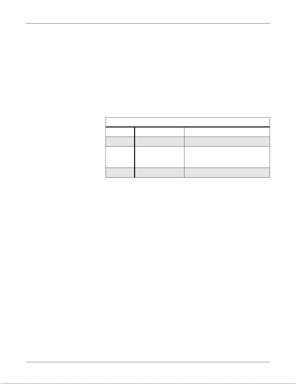
Revision History
Revision Date Comment
A 19 January 1996 Review release of this manual
B 15 November 1996 Initial final release of this
manual—configuration and
peripheral devices were added.
C 30 June 1998 Assemblies were updated
This manual supplies technical information for service representative
and technical personnel so they may maintain the equipment to the
assembly level. Use it as a guide for maintenance and electrical repair
considered field repairable.
Users of this manual are expected to have a strong background in
electronics, inc luding analog and digital circuity with microprocessor and
micro-controller architecture.
If you need parts lists or schematic diagrams for the PCB assemblies,
order the Centralscope Central Station Data Manual , pn 405040-214.
1-2 Centralscope Central Station Revision C
405040-164

INTRODUCTION: Manual Information
Chapter Content
Introduction
Equipment Overview
Configuration
Maintenance
Troubleshooting
Peripheral Devices
Upper Level Assembly
This manual consists of seven sections, summarized as follows:
This section provides general information on the manual itself, related
manuals, safety advice, service requirements and contacts, equipment
symbols, and serial number identification.
Includes a brief description of the transmitter features and technical
specifications.
Includes information for advanced operation and for configuring a
Centralscope central station.
Includes an extensive Preventive Maintenance program, forms for
recording the maintenance steps, and cleaning suggestions.
Includes block diagram theory of operation and some simple
troubleshooting steps that can be performed in the field.
Includes an explanation of how to connect peripheral devices.
Has exploded views, parts lists, inputs/outputs list, and a top level
schematic diagram.
Related Manuals
Part Number Name
405040-214 Centralscope Central Station Data Manual
414993-001 Solar 7000/8000/View Patient Monitor Field Service Manual
414993-007 Solar 7000/8000/View Patient Monitor Data Manual
414993-056 15-Inch Medical-Grade Color Display Service Manual
404183-150 Modular Patient Monitor Accessories Manual
405040-088 Centralscope 12 Central Station Service Manual (Not modular)
405040-018 Centralscope 12C Central Station Service Manual (Not modular)
Check these documents if you need additional information about devices
used with the Centralscope central station.
Service Documents
Revision C Centralscope Central Station 1-3
405040-164

Safety Information
INTRODUCTION: Safety Information
Responsibility of the
Manufacturer
Intended Use
Marquette Medical Systems is responsible for the effects of safety,
reliability, and performance only if:
• assembly operations, extensions, readjustments, modifications, or
repairs are carried out by persons authorized by Marquette Medical
Systems, Inc;
• the electrical installation of the relevant room complies with the
requirements of the appropriate regulations; and
• the device is used in accordance with the instructions for use.
Follow the directives stated below when using any of the transmitter.
• These devices is intended for use under the direct supervision of a
licensed health care practitioner.
• These devices is not intended for home use.
• Federal law restricts these devices to be sold by or on the order of a
physician.
• Contact Marquette Medical Systems for information before
connecting any devices to the equipment that are not recommended
in this manual.
• Parts and accessories used must meet the requirements of the
applicable IEC 601 series safety standards, and/or the system
configuration must meet the requirements of the IEC 601-1-1
medical electrical systems standard.
• Periodically, and whenever the integrity of the device is in doubt, test
all functions.
• The use of ACCESSORY equipment not complying with the
equivalent safety requirements of this equipment may lead to a
reduced level of safety of the resulting system. Consideration
relating to the choice shall include:
use of the accessory in the PATIENT VICINITY; and
◆
evidence that the safety certification of the ACCESSORY has
◆
been performed in accordance to the appropriate IEC 601-1
and/or IEC 601-1-1 harmonized national standard.
• If the installation of the equipment, in the USA, will use 240V rather
than 120V, the source must be a center-tapped, 240V, single-phase
circuit.
1-4 Centralscope Central Station Revision C
405040-164
Equipment Symbols
INTRODUCTION: Safety Information
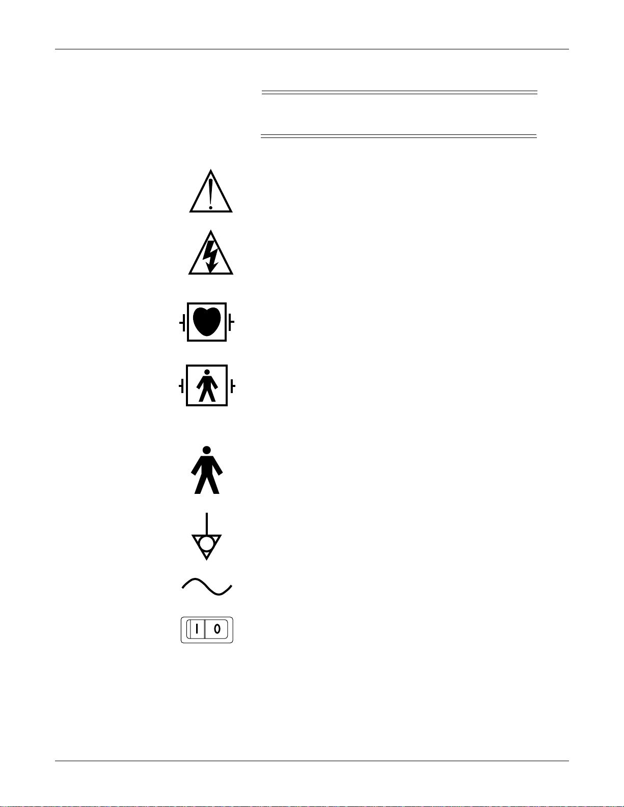
NOTE
Some symbols may not appear on all equipment.
ATTENTION: Consult accompanying documents before using the
equipment.
In Europe, this symbol means dangerous or high voltage. In the
United States, this symbol represents the caution notice below:
To reduce the risk of electric shock, do NOT remove cover (or back).
Refer servicing to qualified personnel.
Defibrillator-proof type CF equipment; type CF equipment is
specifically designed for applications where a conductive connection
directly to the heart is established. The paddles indicate the
equipment is defibrillator proof.
Defibrillator-proof type BF equipment; type BF equipment is
specifically designed for applications intentional external and
internal application to the patient, excluding direct cardiac
application. Type BF equipment is type B equipment with an F-type
isolated (floating) part. The paddles indicate the equipment is
defibrillator proof.
Type B equipment; type B equipment is suitable for intentional
external and internal application to the patient, excluding direct
cardiac application.
Equipotentiality
Alternating current (AC)
Power;
Revision C Centralscope Central Station 1-5
I
= ON;
405040-164
O
= OFF

INTRODUCTION: Safety Information
Fuse
PRESS
Warnings, Cautions,
and Notes
Indicates where to press to open the door on the Series 7160 Direct
Digital Writer .
Warnings and cautions are used throughout this manual to designate a
degree or level of hazardous situations. Hazard is defined as a source of
potential injury to a person.
WARNING
A warning indicates a potential hazard or unsafe practice
which, if not avoided, could result in death or serious
injury.
CAUTION
A caution indicates a potential hazard or unsafe practice
which, if not avoided, could result in minor personal
injury or product/property damage.
Reference Literature
NOTE
A note provide application tips or other useful
information to assure that you get the most from your
equipment.
Medical Device Directive 93/42/EEC
EN 60601-1/1990 + A1: 1993 + A2: 1995: Medical electrical equipment.
General requirements for safety
EN 60601-1-1/9.1994 + A1 12.95: General requirements for safety.
Requirements for the safety of medical electrical systems.
IEC Publication 513/1994: Fundamental aspects of safety standards for
medical equipment.
ROY, O.Z.: Summary of cardiac fibrillation thresholds for 60-Hz currents
and voltages applied directly to the heart. Med. & Biol. Engn. &
Computing 18: 657...659 (1980).
1-6 Centralscope Central Station Revision C
405040-164

INTRODUCTION: Service Information
Service Information
Service
Requirements
Equipment
Identification
Follow the service requirements listed below.
• Refer equipment servicing to Marquette’s authorized service
personnel only.
• Any unauthorized attempt to repair equipment under warranty voids
that warranty.
• It is the user’s responsibility to report the need for service to
Marquette Medical Systems or to one of their authorized agents.
• Failure on the part of the responsible individual, hospital, or
institution using this equipment to implement a satisfactory
maintenance schedule may cause undue equipment failure and
possible health hazards.
• Regular maintenance, irrespective of usage, is essential to ensure
that the equipment will always be functional when required.
Every Marquette Medical Systems device has a unique serial number for
identification. The serial number appears on the product label on the
base of each unit.
D 1 XX 0005 G XX
Month
Manufactured
A = January
B = February
C = March
D = April
E = May
F = June
G = July
H = August
J = September
K = October
L = November
M = December
Warranty
Year
Manufactured
1 = 1991
2 = 1992
3 = 1993
(and so on)
Product Code
Two-character
product
descriptor
1 year.
Product
Sequence
Number
Manufacturing
number (of
total units
manufactured.)
Division
F = Cardiology
G = Monitoring
J = G. W. Labs
Device Characteristics
One or 2 letters that
further describe the unit,
for example:
P = prototype not
conforming to marketing
specification
R = refurbished
equipment
S = special product
documented under
Specials part numbers
U = upgraded unit
Revision C Centralscope Central Station 1-7
405040-164

How to Reach Us
INTRODUCTION: How to Reach Us
Customer Support
and Equipment
Repair Information
Ordering Service
Parts
If you have questions about your monitoring equipment or if you need
service for equipment repair call:
U.S.A and Canada:
Other countries:
Local sales and service
representative:
Service parts are items that are not expended in the normal operation of
the product. They are generally replacements for defective or
malfunctioning items inside the product. Service parts include PCB
assemblies, electronic components, internal cables and harnesses,
software or firmware, and operator and service manuals.
A part number for the item to be replaced is necessary for ordering a
service part. If the part number for the desired item is unobtainable, the
following will be necessary to order the item:
• model and serial number of the equipment
800-558-7044 (24-hour service)
561-575-5000 (during U.S. business hours only)
or contact your local sales and service
representative
Name:
_______________________________________
Telephone:
___________________________________
Supplies Information
• part number/name of the assembly where the item is used,
• item name, and
• where applicable, reference designation (e.g., R13, S12, U32).
Supply items are generally those items used during normal operation of
a product. Leadwires, electrodes, patient cables, printer paper, AquaKnot water traps, airw ay adapters , and calibration gases are examples of
supply items.
Make telephone inquiries about supply items at:
U.S. only: 800-558-5102
Outside U.S.: 561-575-5070 (or contact your local sales and service
representative)
Address orders or inquiries in the U. S. to:
Marquette Medical Systems Service and Supplies
Attention: Supplies Department
100 Marquette Drive
Jupiter, Florida 33468-9100
Fax: 561-575-5050
1-8 Centralscope Central Station Revision C
405040-164

2
EQUIPMENT OVERVIEW
Product Description . . . . . . . . . . . . . . . . . . . . . . . . . . . . . . . . . . . . . . . . .2-2
Controls and Indicators . . . . . . . . . . . . . . . . . . . . . . . . . . . . . . . . . . . . . . 2-3
Back Panel Description . . . . . . . . . . . . . . . . . . . . . . . . . . . . . . . . . . . . . .2-4
Connecting the Display . . . . . . . . . . . . . . . . . . . . . . . . . . . . . . . . . . . . . .2-6
Video Adapters. . . . . . . . . . . . . . . . . . . . . . . . . . . . . . . . . . . . . . . . . .2-6
Connect Video Cable . . . . . . . . . . . . . . . . . . . . . . . . . . . . . . . . . . . . .2-7
Power and Fusing. . . . . . . . . . . . . . . . . . . . . . . . . . . . . . . . . . . . . . . . . . .2-8
Technical Specifications. . . . . . . . . . . . . . . . . . . . . . . . . . . . . . . . . . . . .2-11
Classifications . . . . . . . . . . . . . . . . . . . . . . . . . . . . . . . . . . . . . . . . .2-14
Preparation for Use . . . . . . . . . . . . . . . . . . . . . . . . . . . . . . . . . . . . . . . .2-15
Power Requirements . . . . . . . . . . . . . . . . . . . . . . . . . . . . . . . . . . . .2-15
Equipment Grounding. . . . . . . . . . . . . . . . . . . . . . . . . . . . . . . . . . .2-15
Ventilation Requirements. . . . . . . . . . . . . . . . . . . . . . . . . . . . . . . . 2-16
Installation. . . . . . . . . . . . . . . . . . . . . . . . . . . . . . . . . . . . . . . . . . . .2-16
Revision C Centralscope Central Station 2-1
405040-164

EQUIPMENT OVERVIEW: Product Description
Product Description
The Centralscope central station provides centralized monitoring
functions for patients connected to Marquette monitoring devices on a
Marquette Unity Network. Those devices include Eagle, Tramscope,
Solar and CD Telemetry-LAN monitors.
Data from up to eight patients can be shown on the display
simultaneously. The data for each patient includes waveforms with key
vital signs data expressed in digital form. Users can program patient
displays to “customize” the Central Station for each site, and to
accommodate the dynamic mix of patient monitoring needs.
The Centralscope central station is designed to operate with a variety of
commercially available displays. These displays can be furnished by
Marquette or purchased separately. Specifications for the display are
provided later in this section.
Many central stations are equipped with thermal writers, so that patient
data can be recorded for later review. All central stations contain floppy
disk drives which are used for software updates and for loading
troubleshooting data onto diskettes. (See illustration on following page).
2-2 Centralscope Central Station Revision C
405040-164
EQUIPMENT OVERVIEW: Controls and Indicators
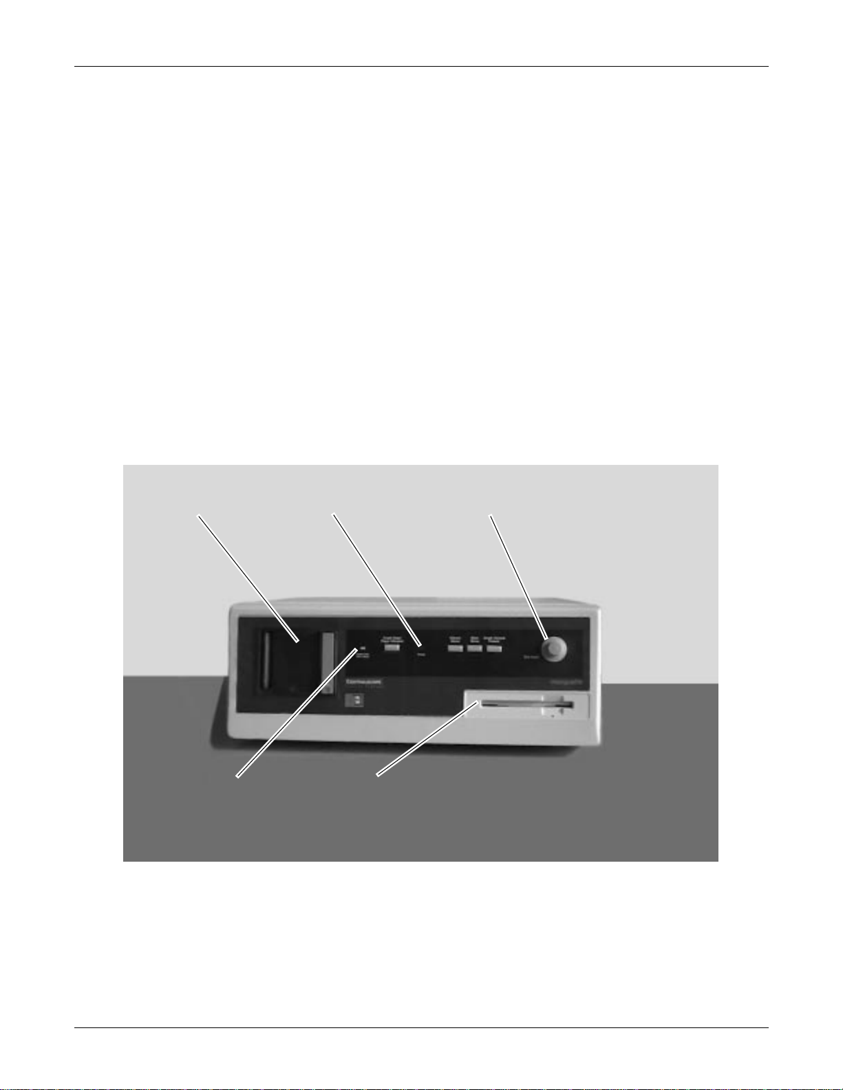
Controls and Indicators
Several controls and indicators are located on the front panel of the
central station. The pushbuttons on the front panel are used to control
the writer paper feed and other central station operator options.
Additional information about these pushbutton switches can be found in
the Operator’s manual.
Trim Knob control
Power LED
Paper Out/Door Open
LED
Thermal Writer
The Trim Knob control is used to control the central station in response
to several software-generated displays. By rotating the Trim Knob
control, various parts of a display are highlighted. To select a particular
highlighted item press inward on the Trim Knob control.
The Power LED indicates when the central station is powered on.
The Paper Out/Door Open LED indicates status of the thermal writer.
Power LED
Trim Knob Control
Paper Out/Door
Open LED
Revision C Centralscope Central Station 2-3
Floppy Disk Drive
405040-164
EQUIPMENT OVERVIEW: Back Panel Description
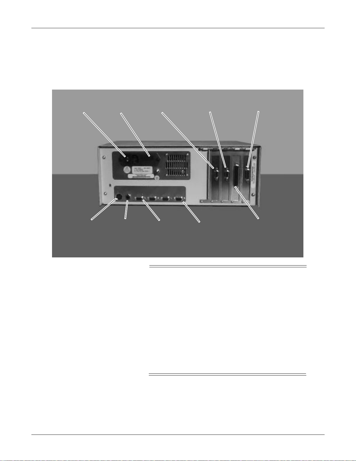
Back Panel Description
The figure below illustrates the connectors, power switch, and fuse
locations on the back panel of the central station.
Power Switch
Keyboard
Fuses
Audio Port 1 Port 4
Remote Video
WARNING
External equipment must be connected to the central
station only by qualified biomedical engineering
personnel.
Primary Video
Network
Analog Output
Only external devices specifically designed to be
connected to the central station, or approved by
Marquette for use with the central station, should be
connected, as specified in this manual or as otherwise
specified by Marquette.
A shock hazard may exist if external devices are
connected other than as shown in this manual or as
directed by Marquette.
Fuses
2-4 Centralscope Central Station Revision C
Fuses are described in more detail later in this chapter.
405040-164

EQUIPMENT OVERVIEW: Back Panel Description
Primary Video
Remote Video
Audio
Ports 1 – 4
The primary video connection is used for the local display (supplied by
customer, or ordered separately from central station). Specifications for
the display are included later in this section.
NOTE
The video adapter must be installed before a display is
connected to this port.
The remote video connection is used for slave displays.
NOTE
The video adapter must be installed before a display is
connected to this port.
The audio connector can drive a cable up to 500 feet (160 meters) long
into an 8-Ω speaker. The RING part of the connector carries all audio
signals (alarms, keyboard, touchscreen). The TIP part of the connector
carries alarm audio only.
The four ports on the back of the central station can be configured for
various remote devices. Configuration of the ports is performed in the
service menus. The port uses are:
Port 1
Port 2
Port 3
Port 4
The Terminal connection can be used to connect a personal computer or
other terminal display device to the central station. This device can then
be used to perform configuration tasks and for troubleshooting, if the
central station display circuits are not functioning properly.
NOTE
If a touch screen is connected to port 4, set the
configuration option to “NOTHING.”
ADU
Writer
Laser Printer
Remote Control
ADU
Writer
Laser Printer
Remote Control
Laser Printer
Terminal
Laser Printer
Touch Screen
Revision C Centralscope Central Station 2-5
405040-164
EQUIPMENT OVERVIEW: Connecting the Display
Connecting the Display
Video Adapters
The Centralscope video adapter kit is used to change the video output
configuration to the pinouts required for use by SVGA displays. Either
one or two adapters are required, depending upon the type of central
station and the video system being used.
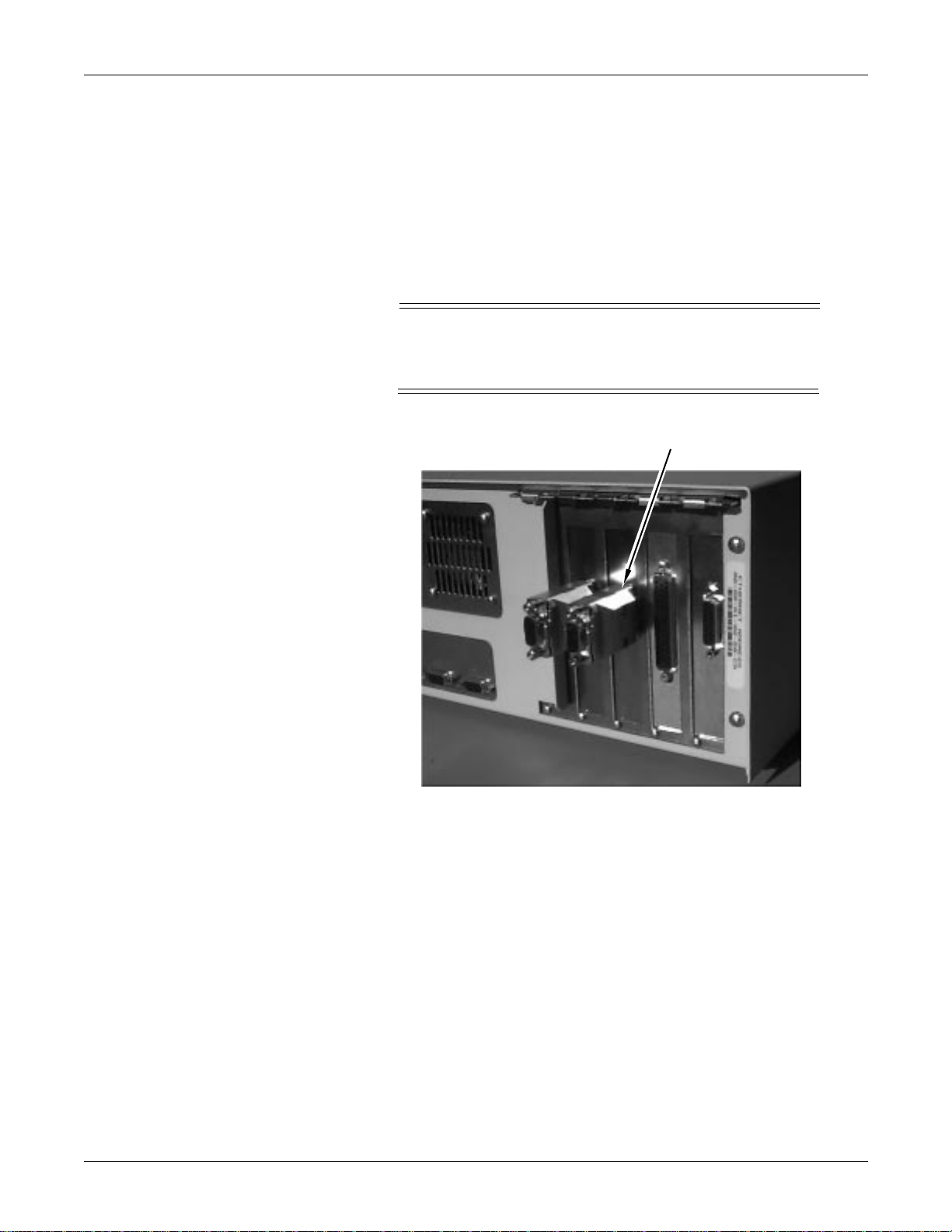
1. Install the video adapter(s), pn 405947-003A, as shown below.
NOTE
The adapter(s) may already be installed, and that there
may only be one adapter supplied with the unit.
Primary Video
Connector
2. Use the jackscrews on each adapter to securely connect the adapter
to the central station.
3. Do not depend upon friction in the connector contacts to attach and
hold the adapter.
2-6 Centralscope Central Station Revision C
405040-164

EQUIPMENT OVERVIEW: Connecting the Display
4. The video cable to the display should also be securely connected to
the video adapter. The video cable is marked with labels identifying
which cable end connects to the central station and which end
connects to the display.
NOTE
The primary video connector is located on the primary
video PCB, which is supposed to be the third circuit board
from the right side of the case.
The connector on the video PCB is used for slave
displays.
Connect Video Cable
Installation of the external monitor requires that the appropriate
interconnect cable be used. Several cables are available, depending on
the display and the connectors on them.
• Verify that the video adapters have been installed (if required),
according to the instructions presented earlier in this section.
• Securely connect the video interconnect cable to the primary video
adapter. (Third connector from right side of the rear panel.)
• Securely connect the video interconnect cables to the external
displays.
• Secure touch screen cable, if applicable, to serial port 4.
• See Chapter 7, “Peripherals,” for cable interconnection.
See Chapter 7, “Peripherals,” for remote display cable interconnection.
Revision C Centralscope Central Station 2-7
405040-164
EQUIPMENT OVERVIEW: Power and Fusing
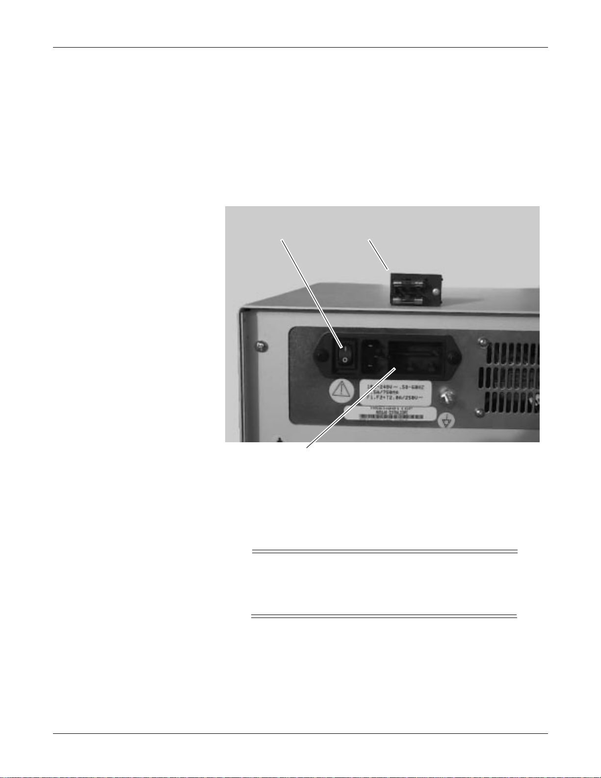
Power and Fusing
Power
The power supply used in the central station auto-adjusts for the power
system it is connected to. No internal adjustments are required. The
power cord is connected to the central station using the power connection
shown in the figure below.
Data about the power supply system is provided in “Technical
Specifications” later in this chapter.
Power Connection Fuse Block
Main Fuse Check
Fuse Block
Receptacle
Main fusing is accomplished through the power input module on the rear
panel. There is also a fuse on the low-voltage power supply. The fuse
arrangement and operating voltage of the Centralscope central station is
set at the factory. Replace the fuses with equivalent devices only,
pn 1908-205.
CAUTION
Replace the fuses in the fuse block with 250 Volt, 2
Ampere fuses only. Improper fusing can result in central
station failure.
2-8 Centralscope Central Station Revision C
405040-164
EQUIPMENT OVERVIEW: Power and Fusing
Use this procedure to check the fuses or change the operating voltage of
the unit.
WARNING
To avoid electric shock, always turn OFF the unit and
remove power cord from AC main outlet before you
replace fuses.
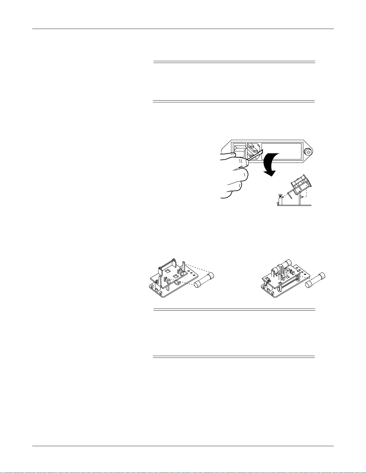
To access the fuses, follow these steps given below.
1. Using a flat blade screwdriver, remove the fuse holder from the
power input module.
I
O
2. Remove the fuse block from the fuse holder by loosening the Phillips-
head screw two full turns counterclockwise.
3. Separate the fuse block from the fuse holder by tilting it up and away
from the mount.
4. Arrange the fuses as required for the proper operating voltage.
For 100/120V AC
For 220/240V AC
NOTE
Two fuses are required for 230/240VAC operation. For
100/120VAC operation, a dummy fuse may be used in the
neutral (lower) holder. Fuses(s) inserted into the power
input module first are the active set.
5. Invert the fuse holder, slide it back onto the screw and pedestal and
tighten the screw.
6. Be sure to seat the fuse block completely in the connector before you
connect power to the central station.
Revision C Centralscope Central Station 2-9
405040-164
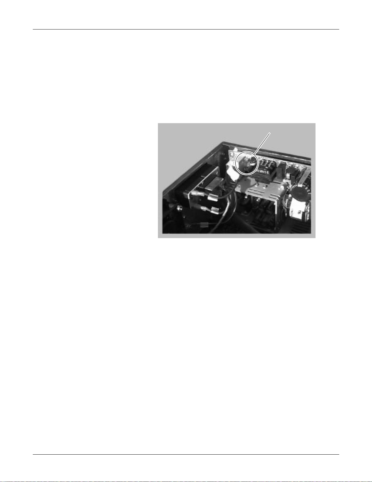
EQUIPMENT OVERVIEW: Power and Fusing
Power Supply Fusing
The power supply in the central station also has a protective fuse. This
fuse provides secondary protection with a higher amperage value than
the main fusing.
Before you replace the power supply fuse, determine and repair the cause
of fuse failure.
If necessary, replace the power supply fuse with a 250 Volt, 3.5 Ampere
fuse.
The illustration below locates the power supply fusing.
Power Supply
Fusing
2-10 Centralscope Central Station Revision C
405040-164

EQUIPMENT OVERVIEW: Technical Specifications
Technical Specifications
Required Display Specifications
Item Description
Electrical Horizontal
Sync rate: 34.4 kHz
Sync input: TTL negative
Blanking: 7.186 µS
Front porch: 1.390 µS
Sync: 2.053 µS
Back porch: 3.743 µS
Vertical
Refresh rate: 60 Hz ± 1 Hz
Sync input: TTL negative
Blanking: 1.774 mS
Front porch: 0.5236 mS
Sync: 0.2036 mS
Back porch: 1.047 mS
Video
Non-composite: 0.7V p-p analog RGB
Polarity: Black-negative
Resolution: 1024 x 768 x 60 Hz
Bandwidth: 60 MHz (recommended)
Input impedance: 75 Ohms
Connections 15-pin, 3-row, high-density subminiature female D-type connector (standard
VGA pinout) or 5 BNC connectors
Emissions MPR II
Agency Approvals UL1950, CSA 950, IEC 950
Revision C Centralscope Central Station 2-11
405040-164

EQUIPMENT OVERVIEW: Technical Specifications
Recommended Display Specifications
Item Description
Display Display area: 12 to 19 inch diagonal (typical)
Dot pitch: 0.28 mm maximum
Brightness: >40 ft. -L
Non-linearity: 2% maximum
Misconvergence: 0.3 mm maximum
Phosphor: Medium to short persistence (such as P22)
Geometric distortion: 2% maximum
CRT surface: Anti-glare coating and transmissiveness of approximately 57%
Controls On/Off, Brightness, Contrast
Operating Voltage 90-135 FAC/60Hz, or 180-270 VAC/50Hz
Environmental Operating temperature: 10 to 40 degrees Celsius
Operating humidity: 10 to 95% (non-condensing)
Weight Maximum weight of 45 Kilograms (100 Pounds) if unit rests on top of central
station housing.
Mounting If the display will be mounted it must accommodate GCX or equivalent
mounting system.
2-12 Centralscope Central Station Revision C
405040-164
EQUIPMENT OVERVIEW: Technical Specifications
Centralscope Central Station Power/Environmental
Item Description
Power Requirements 90 - 264 VAC, 50/60 Hz, single phase
Power Consumption 100 watts (maximum)
Low-voltage Shutdown 90 VAC (for 110 VAC units)
180VAC (for 220VAC units)
Heat dissipation 340 Btu/hour (maximum)
Operating conditions Ambient temperature: 10°C to 35°C (50°F to 95°F)
Relative humidity: 25% to 85% (noncondensing)
Storage Conditions Temperature:-20°C to 60°C (-4°F to 140°F)
Relative humidity: 5% to 95% (noncondensing)
Centralscope Central Station Physical Specifications
Item Description
Height 15.9 cm (6.25 inches)
Width 39.9 cm (15.7 inches)
Depth 43.8 cm (17.25 inches)
Weight 15.5 kg (34 pounds)
Minimum Enclosure
Requirements
(Interior)
Centralscope Central Station Certification
Item Description
Safety Standards ANSI/AAMI EC13
UL 2601-1
IEC 601-1
CSA-C22.2 No. 601.1
Revision C Centralscope Central Station 2-13
405040-164

EQUIPMENT OVERVIEW: Technical Specifications
Classifications
Centralscope central station IBOrdinary Not Suitable NA Continuous
Equipment components are classified, according to IEC-601-1, as:
Type of protection against
electrical shock
Degree of protection against
electrical shock
Key: I: Class I equipment
B: Type B applied part
BF: Type BF applied part
CF: Type CF applied part
NA: Not applicable
Ordinary: Ordinary equipment (enclosed equipment without
protection against ingress of water)
Degree of protection against
harmful ingress of water
Degree of safety of application
in the presence of a flammable
anesthetic mixture with air or
with oxygen or nitrous oxide
Method(s) of sterilization or
disinfection recommended by
the manufacturer
Mode of operation
Not Suitable: Equipment not suitable for use in the presence of a
flammable anesthetic mixture with air or with oxygen or nitrous oxide
2-14 Centralscope Central Station Revision C
405040-164
 Loading...