

Page 1

CardioSmart/CardioSmart ST
Servicing Instructions
Version 1.2 and 1.3
227 435 11 SA(e) Revision D
Page 2

Caution:
During repairs/service interventions,
observe the protective measures against
damage due to ESD.
* Marquette Hellige GmbH considers itself
responsible for the effects on safety,
reliability , and performance of the equipment, only if:
- assembly operations, extensions,
readjustments, modifications, or
repairs are carried out by
Marquette Hellige GmbH or by
persons authorized by Marquette
Hellige GmbH,
- the electrical installation of the
relevant room complies with the
applicable national and local requirements, and
- the instrument is used in accordance
with the instructions for use.
* This manual contains service informati-
on; operating instructions are provided in
the user manual of the instrument.
* This manual is in conformity with the
instrument at printing date.
* All rights are reserved for instruments,
circuits, techniques, and names appearing in the manual.
©
Marquette Hellige GmbH
Printed in Germany
Page 3

Marquette Hellige GmbH CardioSmart/CardioSmart ST V 1.2/ V 1.3
Page 3
227 435 11 D
Contents
1. Device .................................................................. 6
1.1 Block circuit diagram of entire instrument .................................... 9
1.2 Mechanical Components ................................................. 10
2. Functional description ...................................................... 11
2.1 PCB Power Supply_CS .................................................. 11
2.1.1 Switch on/off circuit ............................................... 11
2.1.2 Charging circuit for NC Battery ...................................... 11
2.1.3 Device behavoir depending on the state of battery charge ................... 12
2.2 PCB Control CS_S ..................................................... 13
2.2.1 Generation of the logic power supply +5V .............................. 13
2.2.2 ECG recording and front-end processing ............................... 13
2.2.3 Controller core .................................................. 14
2.2.4 Real-time clock.................................................. 14
2.2.5 Memory ....................................................... 14
2.2.6 Printhead control ................................................ 15
2.2.7 Motor controller ................................................. 15
2.2.8 RS-232 interface ................................................ 16
2.2.9 Keypad interface ................................................ 16
2.3 PCB Graphics Display_CS ............................................... 17
2.3.1 Power supply ................................................... 17
2.3.2 Background illumination ........................................... 17
2.3.3 Contrast control ................................................. 17
2.4 Internal interfaces ...................................................... 18
2.4.1 Mechanical interfaces ............................................. 18
2.4.2 Electronic interfaces .............................................. 19
2.4.2.1 Interface Character Display ........................................ 19
2.4.2.2 Interface Graphics Display .................................... 21
2.4.2.3 Interface PCB Power Supply_CS ............................... 21
2.4.2.4 Option interfaces .......................................... 23
2.5 Interfaces to peripherals ................................................. 24
2.5.1 Electronic interfaces .............................................. 25
2.5.1.1 RS-232 interface .......................................... 26
2.5.1.2 Patient input .............................................. 27
2.6 Limitations .......................................................... 27
3. System test functions ...................................................... 30
3.1 System test functions with graphics display .................................... 30
3.1.1. General information .............................................. 30
3.1.2 Test start ..................................................... 30
3.1.3 Display test (1) ................................................. 31
3.1.4 Key test (2) ................................................... 32
3.1.5 Motor test (3) .................................................. 32
3.1.6 Test results (4) ................................................. 33
3.1.7 Self-test ................................................ 34
3.1.8 Recording test (5) .............................................. 34
3.1.9 Interface test (6) ................................................ 35
3.1.10 Time and date (7) .............................................. 36
3.1.11 Electrode test (8) ............................................... 37
3.1.12 Test time constants (9) ......................................... 38
3.1.13 Setting the Device model (V) ..................................... 38
Page 4

Ma rque tte H e llige G mbH C a rdioS ma rt/ Ca rdioS ma rt S T V 1 . 2 / V 1. 3
Page 4
227 435 11 D
3.1.14 Switching over the program for Interpretation (C) ...................... 40
3.2 Device test functions with character display ................................... 42
3.2.1 General information ............................................. 42
3.2.2 Test start..................................................... 42
3.2.3 Display test (1) ................................................ 42
3.2.4 Key test (2) .................................................. 43
3.2.5 Motor test (3) ................................................. 43
3.2.6 Test results (4) ................................................. 44
3.2.7 Self-test ..................................................... 45
3.2.8 Recording test (5) ............................................. 45
3.2.9 Interface test (6) ............................................... 46
3.2.10 Time and date (7) ............................................... 47
3.2.11 Electrode test (8) ............................................... 48
3.2.12 Test time constants (9) .......................................... 49
3.2.13 Setting the Device model (V) ..................................... 49
3.2.14 Switching over the program for Interpretation (C) ...................... 51
4. Repair instructions......................................................... 52
4.1. Safety instructions ..................................................... 52
4.2 Replacing components .................................................. 52
5. T r oubleshooting tips ....................................................... 56
6. Adjustment instructions ..................................................... 59
7. S e rvicing a nd ma inte na nce .................................................. 61
7.1 Technical inspection .................................................... 61
7.1.1 Visual check ...................................................... 61
7.1.2 Test functions ..................................................... 62
7.1.2.1 Recommended testing instruments and accessories ...................... 62
7.1.2.2 Test preparations ............................................... 62
7.1.2.3 Operating and display unit performance tests ........................... 62
7.1.2.4 Test for recording speeds 25 and 50 mm/s ........................... 63
7.1.2.5 Device test result check .......................................... 63
7.1.2.6 RS232 interface test............................................. 63
7.1.2.7 Analysis of the ECG signals and HR value ............................ 63
7.1.2.8 Pacemaker identification test....................................... 64
7.1.2.9 Identification of disconnected electrodes .............................. 65
7.1.2.10 Checking the charge status of the NC battery ......................... 65
7.1.2.11 Pump leakage ................................................ 65
7.1.3 Safety Analysis Tests ............................................... 66
7.1.3.1 General information ............................................. 66
7.1.3.2 Protective Earth Resistance Test.................................... 66
7.1.3.3 Measurement of Leakage Current ................................... 66
7.1.3.3.1 Enclosure Leakage Current Test ................................ 67
7.1.3.3.2 Patient Leakage Current Test .................................. 68
7.2 Maintenance, cleaning, disinfection .......................................... 69
8. Parts Lists .............................................................. 70
9. Specifications ............................................................ 73
9.1 Specifications CardioSmart ............................................... 73
9.2 Specifications CardioSmart ST............................................. 79
Page 5

Ma rque tte H e llige G mbH C a rdioS ma rt/ Ca rdioS ma rt S T V 1 . 2 / V 1. 3
Page 5
227 435 11 D
10. Device documents ........................................................ 85
Annexe .................................................................. 86
Page 6

Ma rque tte H e llige G mbH C a rdioS ma rt/ Ca rdioS ma rt S T V 1 . 2 / V 1. 3
227 435 11 D
Re vision H istory
V 1.0 May 1995 Initial Release
V 1.1 March 1996 Update 1
V 1.2 February 1997 Update 2
V 1.2/1.3 August 1997 Update 3
Page 6
Page 7

Ma rque tte H e llige G mbH C a rdioS ma rt/ Ca rdioS ma rt S T V 1 . 2 / V 1. 3
227 435 11 D
Page 7
1. D e vice de scription
This Service Manual for device versions V 1.2 and V1.3 describes both CardioSmart
and CardioSmart ST. Unless indicated s pecifically, the description applies t o both
CardioSmart and CardioSmart ST.
The device version V1.3 hardware components are identic al to those of device version
V1.2. The new combinations of these component s in V1.3 result in new models, socalled regional models. Differences between device v ersions V1.2 and V1.3 are
indicated clearly in the relevant sections .
The CardioSmart is a portable electrocardiograph with an int egrated printing unit.
It is used to acquire, record and process ECG signals.
It is designed for line-power and battery operation. O peration without a battery is not
possible. Power supply unit and battery are integrated into the instrument.
CardioSmart ST has an additional ergometry mode opt ion with its own ergometry
keypad.
The patient cable for the acquisition of E CG signals is connected by means of a 15pin connector as used in earlier ECG recorders. This means that the patient cables
used in the past can still be used.
Stored patient data and ECGs can be transmitted to a PC via an RS-232 int erface.
This requires a CardioProm version with additional patient dat a memory.
CardioSmart and CardioSmart ST are both bas ed on the same hardware platform
V1.2 or V1.3 and represent diff erent types of the basic unit 101 116 x x.
With device version V1.2, the following models are available:
101 116 01 CardioSmart international 230V
101 116 02 CardioSmart US Version 115V
101 116 03 CardioSmart Russian 230V
101 116 04 CardioSmart international 230V wit h integrated pump
101 116 05 CardioSmart Russian 230V with integrat ed pump
101 116 10 CardioSmart ST international 230V
101 116 11 CardioSmart ST international 230V with integrated pump
101 116 12 CardioSmart ST US V ersion 115V
101 116 13 CardioSmart ST US V ersion 115V with integrated pump
With device version V1.3, the following models are additionaly available:
101 116 06 CardioSmart EUROPE 2 230V
101 116 07 CardioSmart EUROPE 2 230V with integrated pump
Page 8

Ma rque tte H e llige G mbH C a rdioS ma rt/ Ca rdioS ma rt S T V 1 . 2 / V 1. 3
227 435 11 D
101 116 14 CardioSmart ST Russian 230V
101 116 15 CardioSmart ST Russian 230V with integrated pump
101 116 16 CardioSmart ST EUROPE 2 230V
101 116 17 CardioSmart ST EUROPE 2 230V with integrated pump
101 116 18 CardioSmart ST A SIA 115V/230V
101 116 19 CardioSmart ST AS IA 115V/230V with int egrated pump
The CardioSmart entire instrument comprises t he following components:
Ca rdioS ma rt Ba sic I nstrume nt, wit hout display and CardioProm
-
-
C ardioP rom S t orage M odule , there are several modules wit h different features,
with or without ECG storage facility
CardioVision Display, there are 2 different dis plays available:
-
- CardioVision Text, LCD module 2-line
- CardioVision Graphics, graphics LCD
Page 8
The CardioSmart ST entire instrument c omprises the following components:
CardioSmart ST Basic Instrument, without display and CardioProm
-
-
C ardioP rom S T S t orage M odule , there are several modules wit h different
features, with or without ECG storage facilit y
C ardioV ision G ra phics, graphics LCD
CardioSmart ST is not enabled for CardioVis ion Text
This concept permits the user to conf igure an instrument himself to meet his own
application specifications. It is also possible to upgrade the basic version.
The hardware comprises the following functional blocks:
- P CB Control CS_S (basic instrument)
- P ower supply unit with battery (basic instrument)
- Keypad (basic instrument)
- P rinting unit (basic instrument)
- P CB Energy Storage_CS (storage module)
- D isplay (character or graphics display)
The following functional blocks are constructed directly as PCBs:
- P CB Control_CS
- P CB Energy Storage_CS
- P CB Power Supply_CS with battery charging circuit
- P CB Graphics Display_CS
The applications, functions and operation of the CardioSmart are described in the
User’s Manual.
Page 9
Ma rque tte H e llige G mbH C a rdioS ma rt/ Ca rdioS ma rt S T V 1 . 2 / V 1. 3
Page 9
227 435 11 D
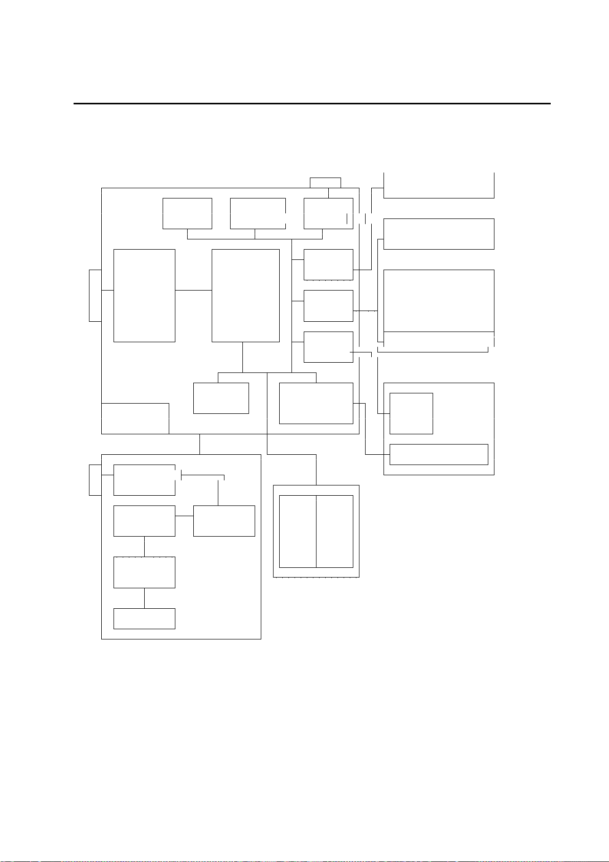
1. 1 Block circuit diagra m of e ntire instrume nt
Config. Clock, RS232
Memory buffered Driver
LCD
Keypad
ECG Interf.
Acquisit. Controller
and Core LCD
Condit- Display
ioning Interf. (optional)
Motor
Contr.
Internal Thermal
RAM Printhead
Generation Controller Motor
+ 5V
Printhead
Line Filt.
Fuse
Generat. Voltage
+ 24V Selector EPROM RAM
(Opt)
Battery
Charge
Battery
PCB Control_CS
Power Supply Unit
Keypad
Character Displ.
Graphics Display
Graphics Controller
Printing Unit
CardioProm
Page 10

Ma rque tte H e llige G mbH C a rdioS ma rt/ Ca rdioS ma rt S T V 1 . 2 / V 1. 3
227 435 11 D
Page 10
1 . 2 M ec hanica l C ompone nts
The main mechanical components comprise the uppe r a nd lowe r she ll of the
Ca rdioS ma rt Ba sic I nstrume nt. The lower shell serves as a basic unit to receive t he
following assemblies:
- M ains input module with instrument On/Off switch
- P CB Power Supply_CS
- Battery
- T hermal printing unit
- P aper container
- P CB Control_CS
The upper shell accommodates the keypad, which is connected to the PCB
Control_CS via a 22-pin connector. The display (c haracter or graphics display) is also
integrated into the upper shell.
CardioProm (program module) also has its own housing, comprising an upper
The
and lower assembly section. It cont ains the PCB Energy Storage_CS , which is
connected to the PCB Control_CS via a multipoint connector when inserted into the
CardioProm slot.
The two available
lower shell. The graphics display contains the graphic s LC display itself, as well as the
associated control electronics, it can be swivelled within the range from 0° to 45° with
5 lock-in positions. The character display only contains the character LCD and cannot
be swivelled. The two displays can be connec ted to the PCB Control_ CS by insert ion
into the depression in the upper shell of the basic instrument provided with a female
multipoint connector.
The 15-pin input connector to
RS-232 interface are located directly on the PCB Control_CS.
the
Models 101 116 04/05 have an added integrated suction pump, comprising the pump
module 303 442 91 and the PCB Pump 388 029 18.
displays are als o located in a housing, comprising an upper and
connect the pa tie nt ca ble and the 9-pin connect or for
Page 11

Ma rque tte H e llige G mbH C a rdioS ma rt/ Ca rdioS ma rt S T V 1 . 2 / V 1. 3
227 435 11 D
Page 11
2 . F unctiona l descr iption
The block circuit diagra m of t he entire instrument in S e ction 1 . 1 and the functional
blocks of the P - pla ns
2 . 1 P C B P owe r S upply_ C S
The PCB Power Supply provides the f ollowing functions:
- S econdary clock-rated power supply unit to generat e the fundamental device
voltage UVERS
- D evice switch on/off circuit
- Charging c ircuit for NC battery
- B attery almost empty identificat ion
- B attery empty instrument swit ch-off
2.1.1 Switch on/off circuit
describe the individual functional blocks.
The device on/off switch (momentary toggle switch) supplies the starting puls e. The
actual stop signal comes from the P CB Control_CS via the DOFF cable.
In the line-power operating mode CardioSmart can be switc hed off by:
- D evice on/off switch
- P rocessor (DOFF)
In the battery operating mode CardioSmart can be s witched off by:
- D evice on/off switch
- P rocessor (DOFF)
- B attery empty identification
In the line-power operating mode recording can be switched off by:
- B attery empty identification
2. 1 . 2 C harging circuit for NC Ba tte ry
A charging IC is used to charge the batt ery. During charging it monitors the battery
voltage function and switches ov er from rapid charging to trickle charging in
conformity with the charging current.
The charging circuit is activated by applying the power supply voltage or battery.
If a recording is made whilst the device is in t he operating mode the charging circuit is
deactivated.
Page 12

Ma rque tte H e llige G mbH C a rdioS ma rt/ Ca rdioS ma rt S T V 1 . 2 / V 1. 3
227 435 11 D
2. 1 . 3 D e vice be ha voir de pe nding on the sta te of ba tte ry cha rge
As a ge ne ra l rule the following a pplie s:
No applied line-power voltage:
Operation of the device without a batt ery is not possible
Applied line-power voltage, battery is charged:
Device completely operational
Applied line-power voltage, battery
depleted:
Device is only partially operational (everything ex cept recording)
Battery charging is triggered by:
Application of line-power voltage
Switching off a current recording, manually with the Stop key
or automatically when the cutoff volt age has been attained
D evice be ha voir:
State 1 Battery depleted, power supply system is connected up:
Battery charged in accelerated mode; when full, switchover to
conservation charging, no time limit
State 2 Battery full, power supply system is connected up:
Battery charged in accelerated mode; when full, switchover to
conservation charging, no time limit
State 3 Batt ery depleted, no line-power supply, device is swit ched on:
Device inoperative
State 4 Batt ery full, no line-power supply, device is swit ched on:
Device fully operative, when battery almos t empty message appears
LEDBAT signal activat ed, when battery empty message appears the
device becomes inoperative
State 5 Battery depleted, power system supply is connected, charging begins,
device is switched on:
All functions except recording, as long as the battery cannot supply the
printhead with sufficient power.
State 6 Battery full, power supply system is connected, device switched on:
Device fully operative. During recording charging is int errupted, at stop
recharging begins until the charging IC switches to conservation
charging.
Page 12
Page 13

Ma rque tte H e llige G mbH C a rdioS ma rt/ Ca rdioS ma rt S T V 1 . 2 / V 1. 3
227 435 11 D
Page 13
2.2 PCB Control CS_S
2. 2 . 1 G e ne ra tion of the logic powe r supply + 5 V
The logic power supply +5V is generated directly on t he PCB Control_CS.
The stabilized voltage UVERS, which is generated by the PC B Power Supply_CS,
serves as the input voltage.
The +5V power supply is generated by the clock -rated
"a djusta ble ve rsion" of the controller is us ed in order to be able to use it later for
The
applications requiring other voltages, the output voltage is determined by appropriate
dimensioning of the voltage divider at the feedbac k input of the voltage controller.
2. 2 . 2 E C G re cording a nd front- e nd proce ssing
The main element of this operational unit is a se t of chips comprising 4 AS I C s located
on the PCB.
The patient lead is connected with a 1 5 - pin conne ctor. Overvoltage arresters at the
electrode inputs provide high-voltage protecti on. A hybrid chip acts as a microfuse f or
each electrode, it serves to identif y a disconnected electrode.
The patient input is classified as cardiac floating and is defibrillation-proof.
Each electrode input is preamplified after t he hybrid chip with a low-noise operational
amplifier with a small input voltage, before it is fed into the two ASICs with t he sigmadelta resistors.
The filter time constants can be adjus ted by the controller core by a command. 8 time
constants are available for selection (system test).
voltage controlle r.
N common-mode compensation ensures suppression of int erference, at the same time
serving to improve the in-phase suppression of t he input electrodes.
To protect patients the ECG recorder and conditioning processor are assembled as
floating components. Digital signals f rom and to the controller core are transmitted via
optoelectronic couplers, the float ing power supply +/-5V is generated by a flyback
converter from the logic power supply +5V.
Page 14

Ma rque tte H e llige G mbH C a rdioS ma rt/ Ca rdioS ma rt S T V 1 . 2 / V 1. 3
227 435 11 D
Page 14
2.2.3 Controller core
The actual core comprises the Motorola Controller 68332, containing the following
integrated components:
- C PU32, computer core, internal 32-bit register, external 16-bit processor
- T PU, an independently operative clock generat or processor
- QSM with SCI to implement a simple RS-232 interface and a serial QSPI
interface with up to 16 channels
- SIM with chipselect generation, system monitoring, clock synthesizer
wat chdog/ re set gene ra tion is implemented with an integrated system monitoring
The
chip. It has the following functi ons:
- P ower-up reset for the 68332 when the instrument is swit ched on
- V oltage monitoring with reset generation
- W atchdog function
- Switchover to battery for buffered RAMs
- A ccess protection for buffered RA Ms
2.2.4 Real-time clock
This provides the time of day and date. When t he device is operative it is powered by
the logic power supply, when the device is sw itched off a 3-V lithium cell is switc hed
in to keep the clock running.
The control signals for the clock (c hipselect read/write signal) are generated in the
PAL RTC_Control, which also contains the release sequenc e for the character display.
2.2.5 Memory
Static RAMs are used as R AM me mory with an internal organiz ation 128kbit x 8. They
are equipped with 4 chips, providing an organisation of 256kbit x 16. It is possible to
add 4 further chips to give a RAM memory area of 1MB yte.
The access time is 70 ns, i.e., access
without wa it sta te s.
Page 15

Ma rque tte H e llige G mbH C a rdioS ma rt/ Ca rdioS ma rt S T V 1 . 2 / V 1. 3
227 435 11 D
Page 15
2.2.6 Printhead control
The printhead controller takes on the complete cont rol of a 216-mm thermal printhead
with a line width of 200 mm. It also contains t he printhead monitor, which reduces the
heating time with increasing printhead temperature, t erminating the printhead power
supply when the printhead temperature reaches 55°C. The printhead power s upply is
reactivated only when the printhead temperature drops below 50°C.
The core is a
The speed-dependent heating parameters are transmitted s erially.
For the printhe ad monitoring t he temperature of the thermal array printhead is
measured by a thermistor located on the printhead. A constant current source effec ts
a temperature-dependent voltage drop at a comparator input, t he switching threshold
being adjusted by hysteresis at the ot her comparator input.
If a printhead temperature of 55°C is exceeded, the message PRINTHEADTE MP is
activated and the current supply to the printhead prevented by the STROBE signal.
Only after the temperature drops below 50°C is the PRI NTHEADTEMP message
disabled and the current supply via STROBE reenabled.
A second comparator generates a VTE MP signal when the temperature reaches
45°C, it is disabled again when the temperature drops below 40°C. It repres ents a
prewarning signal, so that the quantity of data at the printhead is reduced to prevent it
being switched off.
In addition, a continuous reduction in the c urrent activation time occurs with inc reasing
temperature, resulting in a regular type face throughout the entire temperature range.
printhe ad is ope ra te d dire ctly a t the ba tte ry, i.e., the printhead volt age is
The
dependent on the state of battery charge. Compensation is achieved by reducing or
extending the printhead current acti vation time accordingly, ensuring t hat the type face
is maintained within the fluctuation range of t he battery voltage.
gat e a rra y, which t akes on the heating time management for each dot.
2.2.7 Motor controller
This activates the CardioSmart´ s DC motor. This motor does not have a speedo,
control is achieved according to the principle of current compensation.
The main components are the speed selector, motor c ontroller, and motor current
monitoring.
The resistor for the
attached directly to the motor cas ing.
control according to the principle of current c ompensation is
Page 16

Ma rque tte H e llige G mbH C a rdioS ma rt/ Ca rdioS ma rt S T V 1 . 2 / V 1. 3
227 435 11 D
The voltage of +/- 12 V required to send control s ignals is generated from the supply
voltage as follows: An in-phase regulator generates + 12 V, due to the small current
requirements the voltage -12 V is generated by an inv erting voltage pump. The supply
voltage +/-12 V is also used for the temperature monitoring system of the printhead
controller.
It is only enabled during printing!
When the motor current is raised > 140 mA (e.g., as a result of paper jam,
transmission problems) the
transport and the message “Please insert paper and press return key” appears on the
display.
motor current monitoring syste m terminates paper
Page 16
2.2.8 RS-232 interface
The CardioSmart has an RS-232 interface which, except for the RS-232 driver chip, is
directly integrated into the controller.
It has the following attributes:
- S oftware handshake with XON/X OFF
- N o HW handshake
- Transmission speed 1200 .... 19200 B aud
To achieve
additional suppressor diodes.
prote ction a ga inst E S D up to 1 0 kV , the interface is equipped with
2.2.9 Keypad interface
The interface to the keypad is via the 2 2 - pin conne ctor AS . The keypad itself is a
membrane keypad with touch-sensitive chec k-back.
The keypad comprises a
The CardioSmart ST keypad has additional keys for ergometer/treadmill control.
Depending on the keypad used (CardioSmart or CardioSmart S T) the PC receives a
corresponding signal, identifying the devic e used.
Identification of the key press ed is as follows:
The controller activates a column, act ivation is via low-level, simultaneously it reads
out the register for the lines and by a low-level signal ident ifies whether one or more
keys had been pressed. Then the next column is activated. The run procedures are
repeated automatically until all columns have been act ivated.
In addition, the LEDs for start and stop, for the power supply system display and the
battery status control are locat ed directly on the keypad.
mat rix with 7 columns a nd 7 rows.
Page 17

Ma rque tte H e llige G mbH C a rdioS ma rt/ Ca rdioS ma rt S T V 1 . 2 / V 1. 3
227 435 11 D
Page 17
2.3 PCB Graphics Display_CS
This PCB is only used in connecti on with the component parts of the CardioSmart
graphics display unit. It comprises the following functional units:
- V oltage generation
- C PU interface, display control
- B ackground illumination
- C ontrast control
2. 3 . 1 P owe r supply
A negative voltage of -23 V is required for the power supply of the display. It is
generated by an inverting switching controller f rom the 5-V power supply. The output
voltage -23 V is enabled by the additional external wiring of the switching controller.
The voltage -23 V also serves as a voltage s ource for the generation of the negative
contrast volta ge .
The functional unit LC D BLO C K ensures that t he logic power supply +5 V is active at
the graphics display before the negative power supply and the contrast voltage. When
the instrument is switched off the negative power supply and the contrast v oltage are
switched off first.
2 . 3 . 2 Ba ckground illumination
The background illumination of the graphics display is effected by a C F L tube , which
requires an alternating voltage of approx. 800 Vs s.
The alternating voltage is generated by a voltage invert er, driven by 5 V. Since the
CardioSmart is a portable, battery-operated device, t he background illumination can
ena ble d a nd disa ble d (configuration).
be
2.3.3 Contrast control
The contrast control has an additional temperature compensation control. However,
when there are rapid fluctuations in temperature it t akes a certain time until the
compensation is complete, since the dis play itself has a greater thermal time const ant.
Page 18

Ma rque tte H e llige G mbH C a rdioS ma rt/ Ca rdioS ma rt S T V 1 . 2 / V 1. 3
227 435 11 D
Page 18
2.4 Internal interfaces
2.4.1 Mechanical interfaces
The 3 following mechanical interfaces are important within t he CardioSmart:
- I nterface to CardioProm
- Interface to display CardioVision Text
- Interface to display CardioVision Graphic s
Interface to CardioProm
The CardioProm has its own housing, which is conduc ting to prevent damage by ESD.
To shunt any possible static charge it has 3 rails on the underside which, on the PCB
Control_CS in the CardioSmart basic devic e, when inserted make contact with the 3
rails on GND, thereby shunting the charge.
This mechanical insertion of the rails ensures t hat a fail-safe contact is made with the
PCB Control_CS.
Furthermore, mechanical coding ensures that the non-c ompatible CardioProms of the
EK56/EK512 series cannot be inserted into the slot. Similarly, the insertion of
CardioSmart CardioProms into the EK 56/512 slot is not possible.
I nterfa ce to displa y C a rdioV ision T ext
The display CardioVision Text is placed into t he depression provided in the upper
shell of the CardioSmart basic device. The mechanic al rail on the outside of the
display ensures the electrical contac t is automatic and fail-safe. The display
CardioVision Text can be replaced, e.g. , by a CardioVision Graphics using the
appropriate tools without opening the device.
I nte rfac e t o display C a rdioV ision G ra phics
The display CardioVision Graphics is also plac ed in the above-mentioned depression,
the mechanical rail on the outside also ensures a fail-s afe contact. In contrast t o the
CardioVision Text, the CardioVisi on Graphics can only be replaced by opening the
upper shell of the basic device.
Page 19
Ma rque tte H e llige G mbH C a rdioS ma rt/ Ca rdioS ma rt S T V 1 . 2 / V 1. 3
227 435 11 D
Page 19
2.4.2 Electronic interfaces
This section describes the pinning, func tion and significance of the signals of the
internal interfaces of the functi onal components.
2.4.2.1 Interface Character Display
The interface to the character display prov ides all the signals to connect the display
CardioVision Text. It comprises the upper 8 bits of the data bus, control s ignals and
the signal for the contrast cont rol.
Connection denotation:
Female multipoint connector 2 x 7 - pin, upright (180 °), reverse terminal protecti on
achieved mechanically.
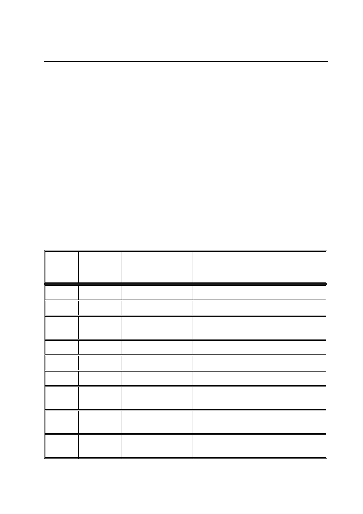
The function of the individual pins is given in t he following table. The definition as an
Input/Output is seen with ref erence to PCB Control_CS.
Pin
Number
1 Output GND System ground
2 Output + 5 V Voltage supply
3 Output CHAR_CONTR
4 Output AD_12 Controller address bus bit 12
Input/Output
AG/
Denotation Function
Contrast character display
0 .... 5V
5 Output RW_ Read/write signal
6 Output ENCHARD Enable character display
7 Bi-Direct,
tristate
8 Bi-Direct,
tristate
9 Bi-Direct,
tristate
DB_8 Controller data bus bit 8
DB_9 Controller data bus bit 9
DB_10 Controller data bus bit 10
Page 20
Ma rque tte H e llige G mbH C a rdioS ma rt/ Ca rdioS ma rt S T V 1 . 2 / V 1. 3
227 435 11 D
Page 20
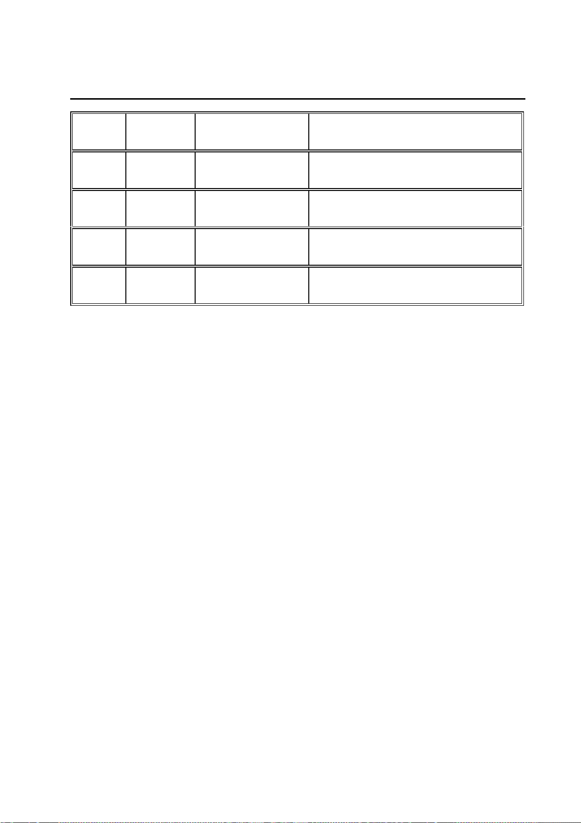
10 Bi-Direct,
tristate
11 Bi-Direct,
tristate
12 Bi-Direct,
tristate
13 Bi-Direct,
tristate
14 Bi-Direct,
tristate
DB_11 Controller data bus bit 11
DB_12 Controller data bus bit 12
DB_13 Controller data bus bit 13
DB_14 Controller data bus bit 14
DB_15 Controller data bus bit 15
2.4.2.2 Interface Graphics Display
The interface to the graphics display provides all the signals to connect the display
CardioVision Graphics. It c omprises the upper 8 bits of the data bus, address bus,
control signals and the signal for the cont rast control.
Connector denotation:
AH/
2. 4 . 2 . 3 I nte rfa ce P C B P owe r S upply_ C S
This has the voltages from the power supply unit to generate the + 5 V and the other
voltages, the control of the LE Ds for the power lamp and battery monitoring, the control
signals for battery charging and switc hing on the printhead and motor power supply as
well as the signal to switch off t he device on the controller´s part.
Connector denotation:
Male multipoint connector 2 x 1 0 - pin, upright (180 °), reverse terminal protection and
coding with coding pin 12.
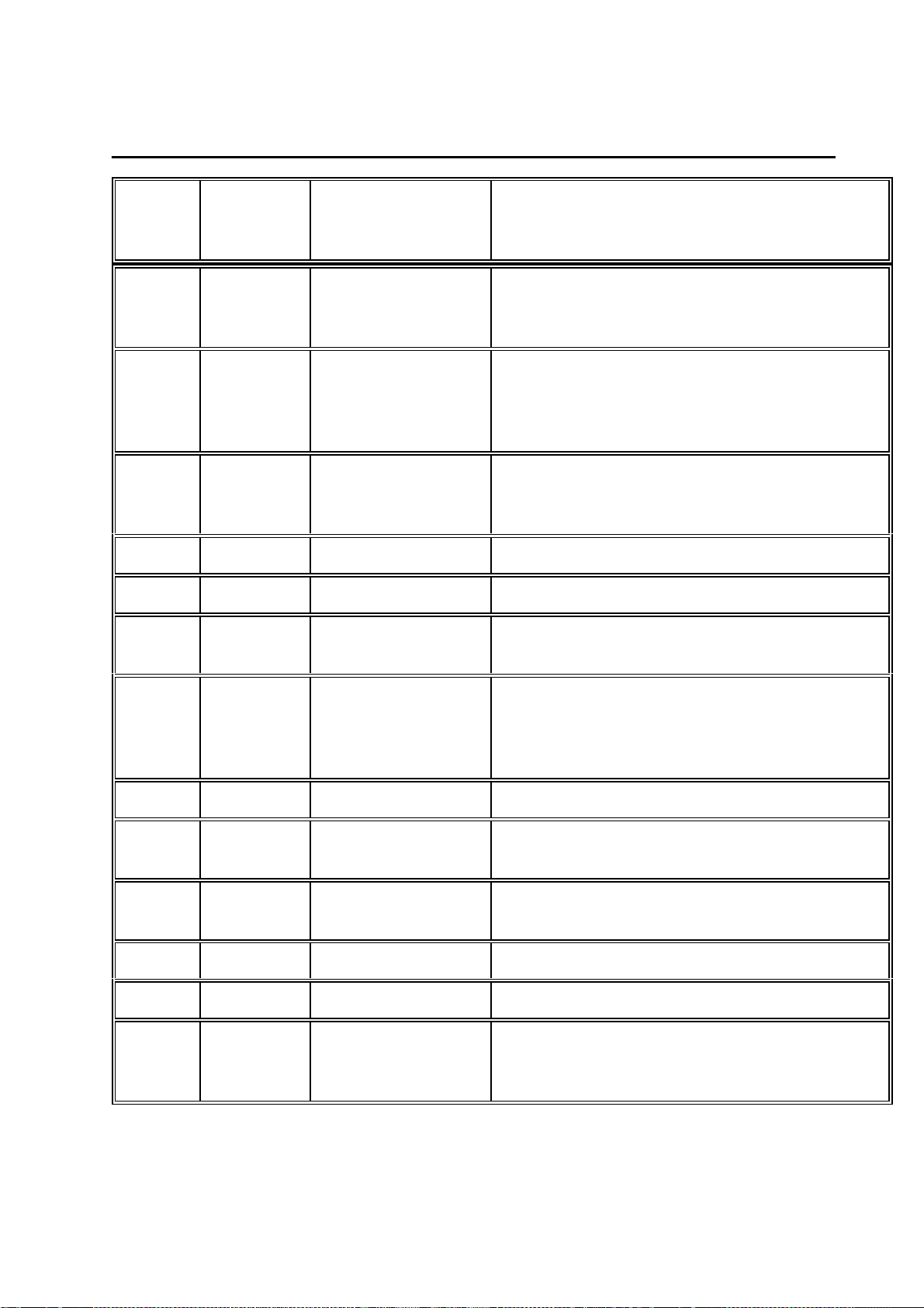
The function of the individual pins is given in t he following table. The definition as an
Input/Output is seen with ref erence to PCB Control_CS.
AE/
Page 21
Ma rque tte H e llige G mbH C a rdioS ma rt/ Ca rdioS ma rt S T V 1 . 2 / V 1. 3
227 435 11 D
Page 21
Pin
Number
1 Input LEDLIN Control of LED for power supply system
2 Output REG_ON Printhead power supply, motor enabled by
3 Output GOFF_ Switch on device with controller
4, 5 Input UVERS Input v oltage to generate +5 V
6 Output + 5 V Logic power supply
7,8,9,
10
Input/Output
Input COMMON_IN Input voltage to generate mot or- printhead
Denotation Function
"-" = mains not connected
"AC" = mains connected
controller:
"0" = Enable battery charging
"1" = Enable printhead power supply
"0" = Device off
"1" = Device on
voltage and +/- 12V
11 Input REG_OFF Printhead power supply, motor enabled by
power-supply unit:
"0" = Enable battery charging
"1" = Enable printhead power supply
12 CODE Coding pin
13, 14,
15, 16
17 Input VRAM Buffered voltage to generate the RAM
18 Output COMMON_S Voltage switched in from COMMON_IN
19 NC NC
20 Input LEDBAT Charging status display for BATTERY:
Input GND System ground
standby power supply
"0" = battery needs charging
"1" = battery charged, normal operat.
Page 22

Ma rque tte H e llige G mbH C a rdioS ma rt/ Ca rdioS ma rt S T V 1 . 2 / V 1. 3
227 435 11 D
Page 22
2.4.2.4 Option interfaces
O ption P owe r C heck
This constitutes a service c onnector to enable checking of all the voltages ac tive within
the system. This
power to other components!
is not a n ex te nsion port, the voltages must not be us ed to supply
Connector denotation:
Male multipoint connector 1 x 6 - pin, upright (180 °), for se rvicing purpose s only!
The function of the individual pins is given in t he following table. The definition as an
Input/Output is seen with ref erence to PCB Control_CS.
Pin
Number
1 Output + 12 V Testing point power supply + 12 V
2 Output GND System ground
3 Output - 12 V Testing point power supply - 12 V
4 Output COMMON_S Testing point power supply motor voltage
Input/Output
AF/
Denotation Function
5 Output GND System ground
6 Output + 5 V Testing point logic power supply + 5 V
Page 23

Ma rque tte H e llige G mbH C a rdioS ma rt/ Ca rdioS ma rt S T V 1 . 2 / V 1. 3
227 435 11 D
Page 23
2.5 Interfaces to peripherals
The CardioSmart has only 3 interfaces for peripherals :
- M ains input
- P atient Input
- R S-232 interface
mains input int erface on the device is a 3-pin standard cold appliance soc ket
The
connection, which is integrated into t he mains input module. Connection to the mains is
effected via a 3-pin power cord with a non-fused earth c onductor.
Although the mains input is not designed as a "wide range input ", adjustment to the
two mains voltage ranges 110V~ ... 120V~ and 220V~ ... 240V~ is easily achieved without
having to open the device or a wiring change of the bridges:
- C heck voltage setting in the inspection window of the interrupter of the mains
input module
- I f the voltage value is not the same as the mains voltage:
D isconnect ma ins plug!
-
- O pen interrupter with appropriate tool
- T ake out fuse holder with fuses
- I nsert fuses rated according to the rating plat e specifications
- R einsert holder so that the required voltage is visible
- C lose interrupter
- T he required mains voltage should now appear in the inspection window
T his rea djustme nt is to be ca rrie d out by the ma nufa cture r or se rvicing age nt only!
No further description of the mechanical and elec tronic parameters of the mains input
is given in Section 2.5.
The mechanics and the interface configuration as used in the EK53/EK56 and in the
EK512 are implemented in the
used up to date can still be used, this also being true for the suction system with its
integrated pump.
A 9-pin sub-D connector with a standard configurat ion of the signals TXD, RXD and
GND is implemented in the construction of the
attached to the connected plug hous ing by means of threaded inserts. The E K53/56
and EK 512 RS-232 power cables can thus no longer be used.
The cable 223 362 03 is used as an RS-232 cable to the PC.
pat ie nt input. This means that all the pat ient cables
RS-232 interface. In addition, it is
Page 24
Ma rque tte H e llige G mbH C a rdioS ma rt/ Ca rdioS ma rt S T V 1 . 2 / V 1. 3
Page 24
227 435 11 D
2.5.1 Electronic interfaces
2.5.1.1 RS-232 interface
This comprises the transmitter signal TX D, the incoming signal RXD and the reference
ground GND. The pin configuration is the same as t hat used for a standard PC 9-pin
sub-D socket. The interface does not operate with a hardware handshake.
Furthermore, a REMOTE START input is provided at pin 8.
Transmission is in accordance with the st andard V-24 protocol, input and output
voltages are defined as follows:
- m aximum input voltage at RXD: +/- 15V
- minimum out put voltage at TXD: +/ - 5 V
- addit ional input protection against ESD ef fects: +/- 10kV
In addition, there is a REMOTE S TART input at pin 8 with the following specif ications:
- ex ternal short-circuiting contact v ia circuit reference referred to ground
- max. source resistor switch: Ri <300
- m ake time >100 ms
- c ontinuous load limits +/-10 V
- E SD protection to max. +/-10 kV
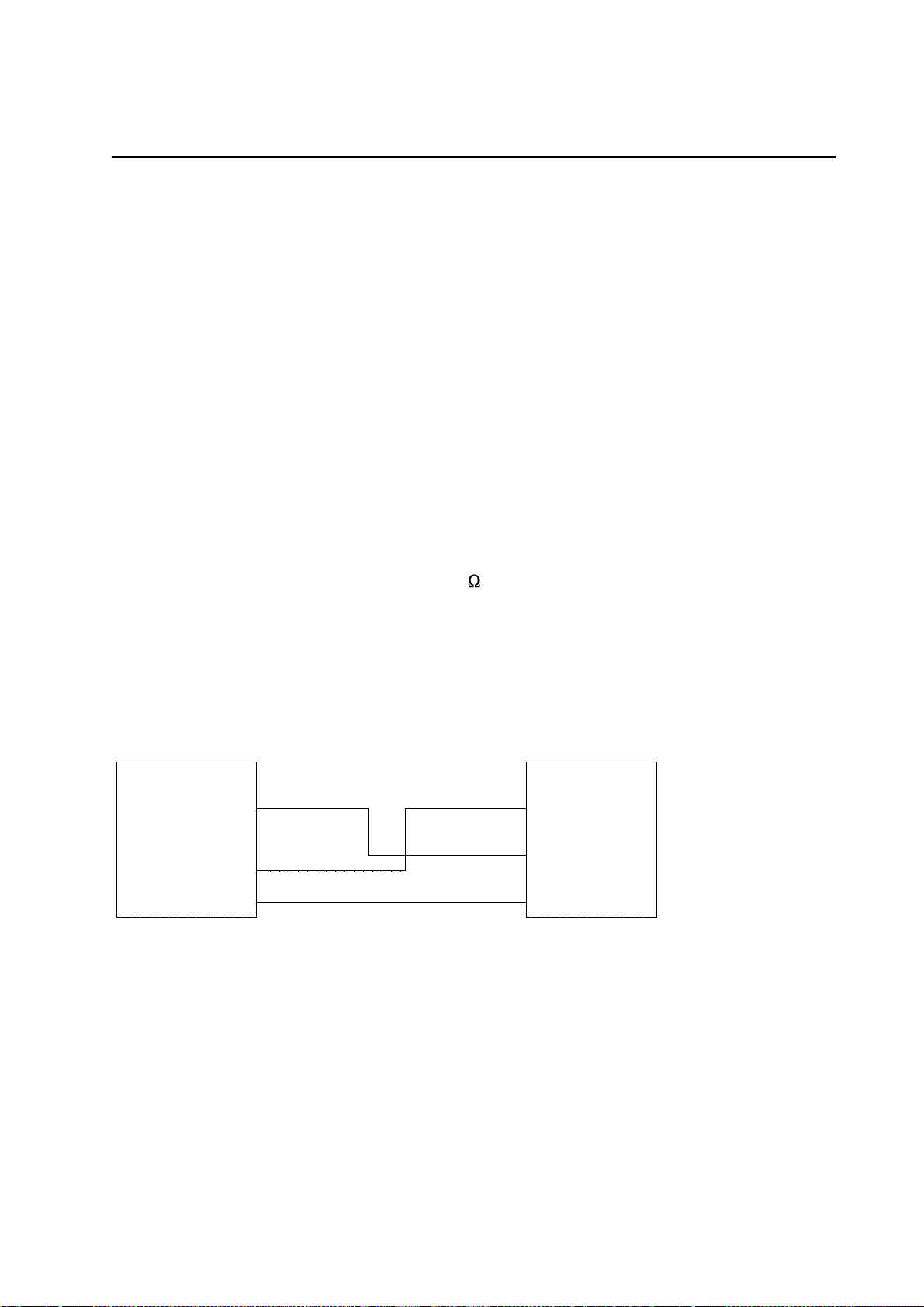
Connection principle to PC
CardioSmart PC
RXDE 2 2 RXD
3 TXD
TXDE 3
GND 5 5 GND
Connection cable 223 362 03
The connector is denoted: AC/
Male multipoint connector sub- D socke t housing, 9 - pin, 9 0° off set
Page 25
Ma rque tte H e llige G mbH C a rdioS ma rt/ Ca rdioS ma rt S T V 1 . 2 / V 1. 3
227 435 11 D
The function of the individual pins is given in t he following table. The definition as an
Input/Output is seen with ref erence to PCB Control_CS.
Page 25
Pin
Number
1 NC NC
2 Input RXDE Receive RS-232 data
3 Output TXDE Transmit RS-232 data
4 NC NC
5 Output GND System ground
6,7,9 NC NC
8 Input REMOTE START Remote Start Input
Input/Output
Denotation Function
Page 26

Ma rque tte H e llige G mbH C a rdioS ma rt/ Ca rdioS ma rt S T V 1 . 2 / V 1. 3
227 435 11 D
2. 5 . 1 . 2 P a tie nt input
Below is a list of the most important features of the patient input:
- Classification: cardiac floating
- Defibrillation-proof
- S imultaneous data acquisition from all leads
- I ndividual electrode monitoring
- V oltage feed for floating power supply via float ing transformer
- C ontrol and data signals from and to floating part via opt oelectronic coupler
Page 26
The connector is denoted:
Male multipoint connector sub- D socke t housing, 1 5 - pin
AA/
Page 27

Ma rque tte H e llige G mbH C a rdioS ma rt/ Ca rdioS ma rt S T V 1 . 2 / V 1. 3
227 435 11 D
The function of the individual pins is given in t he following table. The definition as an
Input/Output is seen with ref erence to PCB Control_CS.
Page 27
Pin
Number
1 Input C2 Input electrode C2
2 Input C3 Input electrode C3
3 Input C4 Input electrode C4
4 Input C5 Input electrode C5
5 Input C6 Input electrode C6
6 Output S Shielding
7 Output PLGND Identification of patient cable used
8 Input PL Identification of patient cable used
9 Input R Input electr ode R
Input/Output
Denotation Function
(Nap for Nehb cables)
10 Input L Input electrode L
11 Input F Input electrode F
12 Input C1 Input electrode C1
13 Input Nst Input elect rode Nst (for Nehb)
14 Output N Output electrode N (common mode
compensation)
15 Input Nax Input electrode Nax ( for Nehb)
Page 28

Ma rque tte H e llige G mbH C a rdioS ma rt/ Ca rdioS ma rt S T V 1 . 2 / V 1. 3
227 435 11 D
2 . 6 Limitations
The following operating modes are not implemented in the CardioSmart:
- N o ergometry
- No SAO2
- N o spirometry
- No late potentials, no RR variability
- N o phono, no US Doppler
A scope output is not available.
No analog inputs.
The existing RS-232 interface does not prov ide an ECG trigger output.
Recording without or with an empty NC battery is not possible.
Page 28
Lead accumulators cannot be used.
Primary cells cannot be used.
Page 29

Ma rque tte H e llige G mbH C a rdioS ma rt/ Ca rdioS ma rt S T V 1 . 2 / V 1. 3
227 435 11 D
Page 29
3 . S yste m te st functions
With country default setting G erman all messages displayed during the self-test are in
German, in all other country settings they appear in English.
3 . 1 Syste m te st functions with gra phics displa y
3 . 1 . 1 . G e ne ra l informa tion
The functions for the system test are mostly menu-guided.
For complete execution some tests require special auxiliary resources. These include
interface testers or PC, c onnection cables, signal generators, etc . The tests that are
necessary are described in the various test descriptions.
3.1.2 Test start
After simultaneously pressing t he keys
the initial display menu appears to enable selection of a s pecific test. (see below)
Keys used for menu selection appear in parenthesis .
(1) Display test
(2) Key test
(3) Motor test
(4) Test results
(5) Recording test
(6) Interface test
(7) Time and date
(8) Electrode test
(9) Time constant test
(V) Device model (from SW V4.21)
(C) 12SL / HEART (from V4.21)
Terminate with SH_MAN or SH_MODE key
S hift + Auto (CardioSmart) or S hift + M ode (CardioSmart ST)
S ystem te st
T est f unctions:
Page 30

Ma rque tte H e llige G mbH C a rdioS ma rt/ Ca rdioS ma rt S T V 1 . 2 / V 1. 3
227 435 11 D
3.1.3 Display test (1)
After pressing the “1" key the f ollowing menu appears:
Page 30
Pressing any other key t han one of those listed in the menu above leads back to the
initial display menu.
Displa y te st
(1) Test pattern
(2) Character set
(3) Delete display
(4) Inverse
(5) Display illumination
Contrast control
- Shift_Cursor_Down
- Shift_Cursor_Up
Terminate with any key
(1) Test pattern
Pressing this key generat es a chessboard pattern. Each s ubsequent pressing
generates the inverse display of its predec essor.
(2) Character set
The character set used for the display is out put.
(3) Delete display
All display pixels are inactive.
(4) Inverse
The contents of the existing dis play appear in reverse video.
( 5) D ispla y illumina tion
The illumination is switched on or off by pressing this key.
C ontrast control
The contrast setting can always be adjus ted as described above (cursor keys).
Page 31

Ma rque tte H e llige G mbH C a rdioS ma rt/ Ca rdioS ma rt S T V 1 . 2 / V 1. 3
227 435 11 D
3.1.4 Key test (2)
By pressing the “2" key the following menu appears :
Page 31
When a key is pressed this key or its f unction is displayed. This can either occ ur by a
triple character display, e.g., “AAA” or as a text, e.g., "CURS_UP". Moreover, pressing
the “P” key tests the bleeper (audible sound) and pres sing the “K” key tests a micro
key to identify whether the cover f or the paper compartment is open or closed. The “E”
key terminates this test and s imultaneously undergoes a self-test.
Key T e s t
(P) Bleeper test
(K) Cover for paper compartment
(E) End
3.1.5 Motor test (3)
When the “3" key is pressed the following menu appears:
Motor/Speed Test
- Speed select key
- Start/Stop
- (A) Measurement marking pulse ON
- (S) Measurement marking pulse OFF
The speed select key is used to set t he required speed and the motor set into motion
with Start/Stop.
Whilst running the motor speed can be controlled by using t he “A” key to activate the
setting of the measurement marking pulse and t o deactivate it with the “S” key. A
making pulse is set once every second. The running speed can then be calculated or
its accuracy checked from t he distance between marking pulses. Any other k ey
pressed not included in this menu leads to the initial dis play menu.
Page 32

Ma rque tte H e llige G mbH C a rdioS ma rt/ Ca rdioS ma rt S T V 1 . 2 / V 1. 3
227 435 11 D
Page 32
3.1.6 Test results (4)
Pressing the “4" key triggers the output of the test res ults.
The output of the test protoc ol supplies data on the software integrat ed in the device
(Part No., Version No., product ion date of the firmware), printhead voltage and the t est
results on the memory test performed during power-up.
The areas listed under RAM have the following meaning:
CardioSmart
0 - 080000h
512 kByte RAM area on the PCB Control CS_S
100000 - 140000h
256 kByte RAM area on the CardioProm (depending on CardioProm type)
140000 - 1C0000h
512 kByte RAM area buffered on the CardioProm (dep. on CardioProm type)
CardioSmart ST
0 - 080000h
512 kByte RAM area on the PCB Control CS_S
100000 - 180000h
256 kByte RAM area on the CardioProm (depending on CardioProm type)
180000 - 200000h
512 kByte RAM area buffered on the CardioProm (dep. on CardioProm ty pe)
Values may deviate from those given above, depending on the device or software
version used.
A specification in the form 100000 - 100000 permits the conclusion that this RAM area
does not exist in the device. However, if it does exist in conformity wit h the software
version implemented, this means that this RAM cell at address 100000H is defective.
The memory could also be defective when the initial and fi nal addresses of the memory
area differ and do not correspond to the above-mentioned limits . This then means, for
example, that the specificat ion 100000 - 123000 on the defective cell at address
123000H.
Following output the initial display menu reappears automatically .
Page 33

Ma rque tte H e llige G mbH C a rdioS ma rt/ Ca rdioS ma rt S T V 1 . 2 / V 1. 3
227 435 11 D
Page 33
3.1.7 Self-test
The test results elucidated in Sect ion 3.1.6 are ascertained during the self-test , which is
always performed on power-up. Should errors be detected, a message appears on the
display after the test, indicat ing the possible errors. The following error codes are used
to identify the error.
E rror code s
The following error codes appear on the display together with the mes sage “Self-test
failed”:
ERROR_CODES: 0 - reserved
1 VEKT - error in vector table
2 ERAM - RAM error on PCB Control
3 LCDR - LCDRAM error (Graphics Display)
4 - reserved
5 - reserved
6 RAMB - RAM error on the CardioProm
7 GRAM - error in buffered RAM on the CardioProm
8 ROMB - ROM error (checksum) on the CardioProm
9 - 10 not used
3.1.8 Recording test (5)
The recording test is activated by pres sing the "5" key and interrupted with the
"Start/Stop" key .
Immediately after pressing the "5" key t he printer begins to record the first channels at
25mm/s and 20mm/mV.
In addition, the message “Recording test ” appears on the display. In this test only t he
first two channels are passed on to t he printer. No other channels can be configured.
Page 34

Ma rque tte H e llige G mbH C a rdioS ma rt/ Ca rdioS ma rt S T V 1 . 2 / V 1. 3
227 435 11 D
Page 34
3.1.9 Interface test (6)
Several possibilities are available to test the serial interface. Moreover, on the one
hand, the signal transmission and rec eiving of the interface can be test ed by an
internal feedback from TXD and RXD and, on t he other hand, the signal transmission
and receiving with a remote station.
For the test with a remote station a st andard PC cable is required for a serial interface
(zero modem cable). In addition, the following trans mission protocol should be adjusted
at the remote station:
1 start bit, 8 data bits, parit y even
1 stop bit
Baud rate 9600
Pressing the “6" key calls up the f ollowing menu:
Interface test
(1) Transmitting and receiving
(2) Transmit test string to device
(3) Transmitting and receiving with device
( 1) T ra nsmitting a nd re ce iving
This test enables complete testing of the RS232 signal path for transmitting and
receiving, including RS232 driver and connector.
This test requires an RS232 connector with an int ernal bridge from pin 2 (RXDE) to pin
(TXDE). Depending on the result of the t est, the following message appears:
Test result : OK
or
Test result : Error
This procedure requires a software version as from V 4.1. Earlier software versions only
permit internal testing of the RS232 interf ace without including the RS232 driver.
(2 ) T ra nsmit te st string to de vice
In this test a remote station, e.g., PC must be connected up and hav e a terminal
program which can receive signals and be configured for the abov e-mentioned
protocol. If the remote stat ion is on receive, then every time the “2" key is pressed the
test string “Interface tes t” is transmitted to the remote st ation. Simultaneously, the
following message appears on the display:
Transmitting : interface test
Page 35

Ma rque tte H e llige G mbH C a rdioS ma rt/ Ca rdioS ma rt S T V 1 . 2 / V 1. 3
227 435 11 D
Page 35
( 3) T ra nsmitting a nd re ce iving with de vice
Transmitting and receiving can be tested with a remot e device by pressing the “3" key.
The device should be connected as described in (2).
After pressing the “3" key a tes t string is sent the remote station. The following
message appears on the display:
Transmitting: interface test
Receiving:
A subsequent input at the remote st ation is sent back to the device and display ed
there. Moreover, it should be noted that an input must take place within 10 s and the
input terminated with “return”. If the k ey is pressed a second time, then the st ring
"CardioSmart Test" is transmitted. Altogether there are three test st rings available,
which are sent in the following sequence with repeated key activation:
"Schnittstellenest", "CardioS mart-Test", "Sieht doch gut aus, oder?"
("Interface Test", CardioSmart Tes t", Looks good, doesn't it?")
The last string corresponds to the expec ted test result.
This test is terminated with any other k ey not used for a test.
3.1.10 Time and date (7)
This section deals with the quick chec king and setting of the time and date.
Pressing the “7" key calls up the f ollowing display:
Time / Date
10:12:03 10.11.1994
(S) Set
End with any key
From this screen the clock can be adjust ed by pressing the “S” key, the following mas k
appearing:
Time Date
[ ] [ ]
The first mask is for the time and t he second for the date.
Example: [1012] [10119] for 10:12 o´clock and 10.11.94
Pressing the return key terminates the entry. The adjusted data are subsequently
accepted and seconds set t o zero.
The test is terminated with any other key not used for a test.
Page 36

Ma rque tte H e llige G mbH C a rdioS ma rt/ Ca rdioS ma rt S T V 1 . 2 / V 1. 3
Page 36
227 435 11 D
3.1.11 Electrode test (8)
The electrode test is started by pres sing the “8" key.
The electrode test is terminated by press ing any key.
To evaluate the electrode states t he following status WORD is available.
Status = 0 -> Electrode OK
Status = 1 -> Electrode disconnected
Bit15 Bit0
----------------------------------------------------------------------| x | x |DAT|ELN|NAP|NST|NAX| C6 | C5 | C4 | C3 | C2 | C1 | F | L | R |
-----------------------------------------------------------------------
And precisely this status WO RD extended to LONG is displayed on the s creen during
the electrode test to be performed. I t is important to note, however, that this status
WORD is not displayed as a binary number but as a hexadec imal number.
However, to make the status of a part icular electrode quickly recognizable, defec tive
electrodes are represented by an ID c ode.
EX_R, for example, stands f or the defective electrode R and C1 for electrode C1.
This permits the identification of ev ery individual electrode. Naturally, since s everal
electrodes can become disconnected simult aneously, it was necessary to set a certain
priority in the display of disconnected elec trodes.
The following display priority was programmed:
EX_R, EL_N, EX_L, EX_F, C1, C2, C3, C4, C5, C6, NAX, NST, NAP
For example, if electrodes R and N have become disconnec ted, then first R is reported
with EX_R as having become disconnect ed. Only after R is OK is E L_N displayed.
Page 37

Ma rque tte H e llige G mbH C a rdioS ma rt/ Ca rdioS ma rt S T V 1 . 2 / V 1. 3
227 435 11 D
Page 37
3.1.12 Test time constants (9)
The test is started by pressing t he “9" key and interrupted with the "Start/S top" key.
Immediately after the “9" key has been act uated the printer begins to record the first
two channels at 25 mm/s and 20 mm/mV.
Moreover, the message “Testing time cons tants” appears on the display.
In this test only the first two channels send signals to the printer. No ot her channels
can be configured. The default time const ant is output on the printout as a control.
S etting the time consta nts
As a general rule, the time const ants are adjusted to 2.04 s.
This setting can be changed with the CORR_CO NFIG key.
The following settings are available:
Time constants:
(1) 0.260s (2) 0.130s (3) 0.033s
(4) 0.004s (5) 4.080s (6) 2.040s
(7) 1.020s (8) 0.510s
The figures given in parentheses indicate the key used to select the corresponding time
constant.
Verification of the currently ac tive time constant is only poss ible by printing out the selftest results (see Section 3. 1.6) or by testing the time constant s.
3.1.13 Setting the Device models (V)
The setting of the Device model is act ivated by pressing the “V” key, t he following
display image appears:
D e v i c e mode l
(1) INT
(2) USA
(3) EU_2
(4) ASIA
(5) RUSS
Terminate with any key.
The currently selected device model appears in reverse v ideo.
Page 38

Ma rque tte H e llige G mbH C a rdioS ma rt/ Ca rdioS ma rt S T V 1 . 2 / V 1. 3
Page 38
227 435 11 D
Warning!
C hanging the de vice mode l a ffe cts the se le ction of the output forma ts a nd la ngua ges
ava ila ble , can switch the program for I nte rpreta tion from HE AR T to 1 2 SL, or vice
versa . Also a ff ecte d a re the de fa ult configura tion se ttings, e . g. , ove rride function
yes/no, line filter 50/60 Hz.
T he de vice mode l configure d during ma nufa cture should only be cha nge d whe n
deemed really necessary.
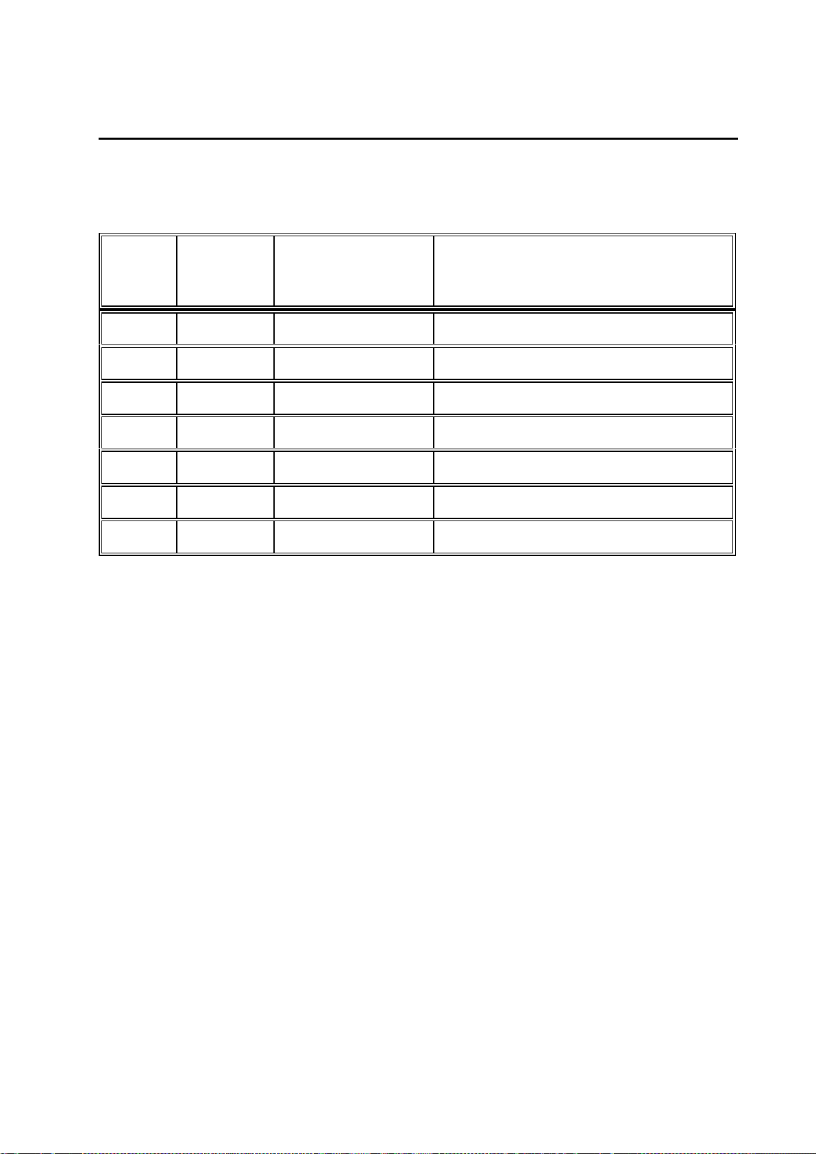
The following table shows the most important combinat ions:
Device model Interpretation Output
formats
01 INT HEART International g,e,f,i,s no 50 Hz
02 USA 12SL USA e,f,s yes 60 Hz
03 EU_2 12SL Int. +H1 +H2 e,g,f,sw yes 50 Hz
04 ASIA HEART International g,e,f no 50 Hz
05 RUSS HEART International g,e,f no 50 Hz
Languages Default settings
Override
function
enabled
Line filter
Output formats: - International: 12_FS, 12_F1, 12_F2, 6_F1, 6_F2, 3_F1
- USA: STND1, STND3, 1x10, 2x5, 2x5_ex, 3RHY1
The required device model is selected by pressing the appropriat e key, “1" to “5".
Quit selection menu by pressing any key .
Quit the self-test with “Shift ” + “Man” or “Shift” + “Mode”.
CardioSmart configures the appropriate items and init iates a cold start automatically.
Thus, when the device is rebooted automatically all the new settings are adopted.
Selecting a particular device model leads to t he configuration of the program for
Interpretation as indicated in the table above, even when the interpretation program
was configured differently beforehand as desc ribed in section 3.1.14.
N ote on sa ve d E C G s whe n configuring the de vice mode l:
Saved ECGs are not los t.
If when a new device model is selected, the program f or Interpretation is switched over,
however, when printing out the saved ECGs t he display in the status line (12SL, or
without in the case of HEART) is related to the currently enabled program for
Page 39

Ma rque tte H e llige G mbH C a rdioS ma rt/ Ca rdioS ma rt S T V 1 . 2 / V 1. 3
227 435 11 D
Interpretation, although the results are based on the program previously configured. In
this case, the saved E CGs should be printed out or transf erred to a PC before
configuration of the new model.
Page 39
3.1.14 Switching over the program for Interpretation(C)
Switching over the program for Interpretat ion is activated by pressing the “C” key , the
following display image appears:
I n t e r p r e t a t i o n
(1) HEART
(2) 12SL
Terminate with any key.
The currently enabled interpretation program appears in reverse video.
Warning!
S witching ove r to anot her progra m for I nte rpre ta tion a ffe cts the me a sure me nt re sults
and the inte rpreta tion!
T he progra m for I nt erpre ta tion conf igured during ma nufa cture should only be cha nge d
when deemed really necessary!
The required program for Interpretation is selected by pres sing the appropriate key, “1"
or “2".
Quit the selection menu by pressing any key.
Quit the self-test with “Shift ” + “Man” or “Shift” + “Mode”.
CardioSmart configures the appropriate items and init iates a cold start automatically.
Thus, when the device is rebooted automatically all the new settings are adopted.
N ote on sa ve d E C G s whe n switching ove r the progra n for I nte rpre ta tion:
Saved ECGs are not los t.
After switching over to a diff erent program for Interpretation when printing the saved
ECGs the display in the st atus line (12SL, or without in the case of HE ART) is related
to the newly selected interpretation program, alt hough the results are based on the
program previously configured. In this cas e the saved ECGs should be printed out or
transferred to a PC before switc hing over to the new program for Interpretation.
Page 40

Ma rque tte H e llige G mbH C a rdioS ma rt/ Ca rdioS ma rt S T V 1 . 2 / V 1. 3
227 435 11 D
Page 40
3 . 2 D evice te st functions with cha ra cte r displa y
( only Ca rdioS ma rt)
3 . 2 . 1 G e ne ra l informa tion
In contrast to the graphics display , at the current time the device tes t functions all
require menu-guided execution. This is because the renditi on of the character display
of max. 80 characters is very limit ed.
To be performed in their entirety some tests require special auxiliary aids, e.g.,
interface tester or PC, connec tion cables, signal generators, etc. Just what is required
for which test are given in the various tes t descriptions.
3.2.2 Test start
After simultaneous pressing of t he keys
S hift + Auto (CardioSmart) or S hift + M ode (CardioSmart ST)
the following initial display image appears:
END TEST: with Shift MAN
(CardioSmart ST)
Key used to select menu options are given in parentheses.
S Y S T E M T E S T
(CardioSmart) or Shift + Mode
3.2.3 Display test (1)
After pressing the “1" key the f ollowing menu appears:
Display test
(3) Delete display (4) Inverse
Pressing any other key than thos e given above leads back to the initial display image.
(3) Delete display
All the display pixels are disabled.
(4) Inverse
Inverse here does not mean inverse display of the rendered t ext, but inverse to delete
display, i.e., all the display pixels are enabled.
Page 41

Ma rque tte H e llige G mbH C a rdioS ma rt/ Ca rdioS ma rt S T V 1 . 2 / V 1. 3
227 435 11 D
C ontrast control
Furthermore, the contrast control c an also be adjusted under this option “Display test”.
Moreover, there are 7 levels available which can be run though with the CURSOR_UP
and CURSOR_DOWN keys.
3.2.4 Key test (2)
Pressing the “2" key calls up the f ollowing screen:
Page 41
(E) End
When a key is pressed this or its meaning is display ed. This can either occur by a
triple character display, e.g., “AAA” or as a text, e.g., "CURS_UP". Moreover, pressing
the “P” key tests the bleeper (audible sound) and pres sing the “K” key tests a micro
key to identify whether the cover f or the paper compartment is open or closed. The “E”
key terminates this test and s imultaneously undergoes a self-test. The initial dis play
image appears.
K e y T e s t
3.2.5 Motor test (3)
When the “3" key is pressed the following menu appears:
The speed select key is used to set t he required speed and the motor set into motion
with Start/Stop.
Whilst running the motor speed can be controlled by using t he “A” key to activate the
setting of the measurement marking pulse and t o deactivate it with the “S” key. A
marking pulse is set once every second. The running s peed can then be calculated or
its accuracy checked from t he distance between marking pulses.
Any other key pressed not included in t his menu leads to the initial display menu.
Motor/Speed Test
Page 42

Ma rque tte H e llige G mbH C a rdioS ma rt/ Ca rdioS ma rt S T V 1 . 2 / V 1. 3
227 435 11 D
Page 42
3.2.6 Test results (4)
Pressing the “4" key triggers the output of the test res ults.
The output of the test protoc ol supplies data on the software integrat ed in the device
(Part No., Version No., product ion date of the firmware), printhead voltage and the t est
results on the memory test performed during power-up.
The areas listed under RAM have the following meaning:
Car dioSmart
0 - 080000h
512 kByte RAM area on the PCB Control CS_S
100000 - 140000h
256 kByte RAM area on the CardioProm (depending on CardioProm type)
140000 - 1C0000h
512 kByte RAM area buffered on the CardioProm (dep. on CardioProm
type)
CardioSmart ST
0 - 080000h
512 kByte RAM area on the PCB Control CS_S
100000 - 180000h
256 kByte RAM area on the CardioProm (depending on CardioProm type)
180000 - 200000h
512 kByte RAM area buffered on the CardioProm (dep. on CardioProm
type)
Values may deviate from those given above depending on t he device or software
version used.
A specification in the form 100000 - 100000 permits the conclusion that this RAM area
does not exist in the device. However, if it does exist in conformity wit h the software
version implemented, this means that this RAM cell at address 100000H is defective.
The memory could also be defective when the initial and fi nal addresses of the memory
area differ and do not correspond to the above-mentioned limits . This then means, for
example, that the specificat ion 100000 - 123000 on the defective cell at address
123000H.
The output can be interrupted with the Start /Stop key. Following output the initial
Page 43

Ma rque tte H e llige G mbH C a rdioS ma rt/ Ca rdioS ma rt S T V 1 . 2 / V 1. 3
227 435 11 D
display menu reappears automatically.
Page 43
3.2.7 Self-test
The test results elucidated in Sect ion 3.2.6 are ascertained during the self-test , which is
always performed on power-up. Should errors be detected, a message appears on the
display after the test indicating t he possible errors. The following error codes are used
to identify the error.
E rror code s
The following error codes appear on the display together with the mes sage “Self-test
failed”:
ERROR_CODES: 0 - reserved
1 VEKT - error in vector table
2 ERAM - RAM error on PCB Control
3 LCDR - LCDRAM error (G raphics Display)
4 - reserved
5 - reserved
6 RAMB - RAM error on the CardioProm
7 GRAM - error in buffered RAM on the CardioProm
8 ROMB - ROM error (checksum) on the CardioProm
9 - 10 not used
3.2.8 R e cor ding te st (5)
The recording test is activated by pres sing the "5" key and interrupted with the
"Start/Stop" key .
Immediately after pressing the "5" key t he printer begins to record the first channels at
25mm/s and 20mm/mV.
In addition, the message “Recording test ” appears on the display. In this test only t he
first two channels are passed on to t he printer. No other channels can be configured.
Page 44

Ma rque tte H e llige G mbH C a rdioS ma rt/ Ca rdioS ma rt S T V 1 . 2 / V 1. 3
227 435 11 D
Page 44
3.2.9 Interface test (6)
Several possibilities are available to test the serial interface. Moreover, on the one
hand, the signal transmission and rec eiving of the interface can be test ed by an
internal feedback from TXD and RXD and, on t he other hand, the signal transmission
and receiving with a remote station.
For the test with a remote station a st andard PC cable is required for a serial interface
(zero modem cable). In addition, the following trans mission protocol should be adjusted
at the remote station:
1 start bit, 8 data bits, parity even
1 stop bit
Baud rate 9600
Pressing the “6" key calls up the f ollowing menu:
Interface test Keys (1), (2), (3)
‘1' key te sts transmission and re ce iving
( 1) T ra nsmitting a nd re ce iving
This test enables complete testing of the RS232 signal path for transmitting and
receiving, including RS232 driver and connector.
This test requires an RS232 connector with an int ernal bridge from pin 2 (RXDE) to pin
(TXDE). Depending on the result of the t est, the following message appears:
Test result : OK
or
Test result : Error
This procedure requires a software version as from V 4.1. Earlier software versions only
permit internal testing of the RS232 interf ace without including the RS232 driver.
(2 ) T ra nsmit te st string to de vice
In this test a remote station, e.g., PC must be connected up and hav e a terminal
program which can receive signals and be configured for the abov e-mentioned
protocol. If the remote stat ion is on receive, then every time the “2" key is actuated the
test string “Interface tes t” is transmitted to the remote st ation. Simultaneously, the
following message appears on the display:
Transmitting : interface test
Page 45

Ma rque tte H e llige G mbH C a rdioS ma rt/ Ca rdioS ma rt S T V 1 . 2 / V 1. 3
227 435 11 D
( 3) T ra nsmitting a nd re ce iving with de vice
Transmitting and receiving can be tested with a remot e device by pressing the “3" key.
The device should be connected as described in (2).
After pressing the “3" key a tes t string is sent the remote station. The following
message appears on the display:
Interface test Keys (1), (2), (3)
A subsequent input at the remote st ation is sent back to the device and display ed
there. A received text would then be dis played on the second line of the screen.
Moreover, it should be noted that an input must take place within 10 s and the input
terminated with “return”. If the key is actuated a second time then the string
"CardioSmart Test" is transmitted. Altogether there are three test st rings available,
which are sent in the following sequence with repeated key actuation:
"Interface Test", "CardioSmart Tes t", "Looks good, doesn´t it?"
The last string corresponds to the expec ted test result.
This test is terminated with any other k ey not used to start a test.
Page 45
3.2.10 Time and date (7)
This section deals with the quick chec king and setting of the time and date.
Pressing the “7" key calls up the f ollowing display:
Time / Date
10:12:03 10.11.1994
From this screen the clock can be adjust ed by pressing the “S” key the following mask
appearing:
Time Date
[ ] [ ]
The first mask is for the time and t he second for the date.
Example: [1012] [10119] for 10:12 o´clock and 10.11.94
Pressing the return key terminates the entry. The adjusted data are subsequently
accepted and seconds set t o zero.
The test is terminated with any other key not used for a test.
Page 46

Ma rque tte H e llige G mbH C a rdioS ma rt/ Ca rdioS ma rt S T V 1 . 2 / V 1. 3
Page 46
227 435 11 D
3.2.11 Electrode test (8)
The electrode test is started by pres sing the “8" key.
The electrode test is terminated by press ing any key.
To evaluate the electrode states t he following status WORD is available.
Status = 0 -> Electrode OK
Status = 1 -> Electrode disconnected
Bit15 Bit0
----------------------------------------------------------------------| x | x |DAT|ELN|NAP|NST|NAX| C6 | C5 | C4 | C3 | C2 | C1 | F | L | R |
-----------------------------------------------------------------------
And precisely this status WO RD extended to LONG is displayed on the s creen during
the electrode test to be performed. I t is important to note, however, that this status
WORD is not displayed as a binary number but as a hexadec imal number.
However, to make the status of a part icular electrode quickly recognizable, defec tive
electrodes are represented by an ID c ode.
EX_R, for example, stands f or the defective electrode R and C1 for electrode C1.
This permits the identification of ev ery individual electrode. Naturally, since s everal
electrodes can become disconnected simult aneously, it was necessary to set a certain
priority in the display of disconnected elec trodes.
The following display priority was programmed:
EX_R, EL_N, EX_L, EX_F, C1, C2, C3, C4, C5, C6, NAX, NST, NAP
For example, if electrodes R and N have become disconnec ted, then first R is reported
with EX_R as having become disconnect ed. Only after R is OK is E L_N displayed.
3.2.12 Test time constants
(9)
The test is started by pressing t he “9" key and interrupted with the "Start/S top" key.
Immediately after the “9" key has been act uated the printer begins to record the first
two channels at 25 mm/s and 20 mm/mV.
Moreover, the message “Testing time cons tants” appears on the display.
In this test only the first two channels send signals to the printer. No ot her channels
can be configured. The default time const ant is output on the printout as a control.
Page 47

Ma rque tte H e llige G mbH C a rdioS ma rt/ Ca rdioS ma rt S T V 1 . 2 / V 1. 3
227 435 11 D
S etting the time consta nts
As a general rule, the time const ants are adjusted to 2.04 s.
This setting can be changed with the CORR_CO NFIG key.
The following settings are available:
Time constants:
(1) 0.260s (2) 0.130s (3) 0.033s
(4) 0.004s (5) 4.080s (6) 2.040s
(7) 1.020s (8) 0.510s
The figures given in parentheses indicate the key used to select the corresponding time
constant.
Verification of the currently ac tive time constant is only poss ible by printing out the selftest results (see Section 3. 2.6) or by testing the time constant s (see Section 5.2.8).
Page 47
3.2.13 Setting the Device model (V)
This setting is only available form Sof tware Release V4.21.
Setting the Device model is acti vated by pressing the “V” key, the f ollowing display
image appears:
D e v i c e M o d e l --> (1) INT
(1) INT (2) USA (3) EU_2 (4) ASIA (5) RUSS
Terminate with any key.
The currently enabled device model appears in line 1.
Warning!
C hanging the de vice mode l a ffe cts the se le ction of the output forma ts a nd la ngua ges
ava ila ble , can switch the program for I nte rpreta tion from HE AR T to 1 2 SL, or vice
versa . Also a ff ecte d a re the de fa ult configura tion se ttings, e . g. , ove rride function
yes/ no, line filter 50/60 Hz.
T he de vice mode l configure d during ma nufa cture should only be cha nge d whe n
deemed really necessary.
The following table shows the most important combinat ions:
Page 48

Ma rque tte H e llige G mbH C a rdioS ma rt/ Ca rdioS ma rt S T V 1 . 2 / V 1. 3
227 435 11 D
Page 48
Device model Interpretation Output
formats
01 INT HEART International g,e,f,i,s no 50 Hz
02 USA 12SL USA e,f,s yes 60 Hz
03 EU_2 12SL Int. +H1 +H2 e,g,f,sw yes 50 Hz
04 ASIA HEART International g,e,f no 50 Hz
05 RUSS HEART International g,e,f no 50 Hz
Languages Default settings
Override
function
enabled
Line filter
Output formats: - International: 12_FS, 12_F1, 12_F2, 6_1F, 6_F2, 3_F1
- USA: STND1, STND3, 1x10, 2x5, 2x5_ex, 3RHY1
The required device model is selected by pressing the appropriat e key, “1" to “5".
Quit selection menu by pressing any key .
Quit the self-test with “Shift ” + “Man” or “Shift” + “Mode”.
CardioSmart configures the appropriate items and init iates a cold start automatically.
Thus, when the device is rebooted automatically all the new settings are adopted.
Selecting a particular device model leads to t he configuration of the program for
Interpretation as indicated in the table above, even when the interpretation program
was configured differently beforehand as desc ribed in section 3.2.14.
N ote on sa ve d E C G s whe n configuring the de vice mode l:
Saved ECGs are not los t.
If when a new device model is selected, the program f or Interpretation is switched over,
however, when printing out the saved ECGs t he display in the status line (12SL, or
without in the case of HEART) is related to the currently enabled program for
Interpretation, although the results are based on the program previously configured. In
this case, the saved E CGs should be printed out or transf erred to a PC before
configuration of the new model.
Page 49

Ma rque tte H e llige G mbH C a rdioS ma rt/ Ca rdioS ma rt S T V 1 . 2 / V 1. 3
227 435 11 D
Page 49
3.2.14 Switching over the program for I nterpretation (C)
Switching over the program for interpretation is activated by pressing the “C” key, the
following display image appears:
I n t e r p r e t a t i o n --> (1) HEART
Terminate with any key.
The currently enabled device model appears in line 1.
Warning!
S witching ove r to anot her progra m for I nte rpre ta tion a ffe cts the me a sure me nt re sults
and the inte rpreta tion!
T he progra m for I nt erpre ta tion conf igured during ma nufa cture should only be cha nge d
when deemed really necessary!
The required program for Interpretation is selected by pres sing the appropriate key, “1"
or “2":
“1" for HEART, or “2" for 12SL.
Quit the selection menu by pressing any key.
Quit the self-test with “Shift ” + “Man” or “Shift” + “Mode”.
CardioSmart configures the appropriate items and init iates a cold start automatically.
Thus, when the device is rebooted automatically all the new settings are adopted.
N ote on sa ve d E C G s whe n switching ove r the progra n for I nte rpre ta tion:
Saved ECGs are not los t.
After switching over to a diff erent program for Interpretation when printing the saved
ECGs the display in the st atus line (12SL, or without in the case of HE ART) is related
to the newly selected interpretation program, alt hough the results are based on the
program previously configured. In this cas e the saved ECGs should be printed out or
transferred to a PC before switc hing over to the new program for Interpretation.
Page 50

Ma rque tte H e llige G mbH C a rdioS ma rt/ Ca rdioS ma rt S T V 1 . 2 / V 1. 3
227 435 11 D
Page 50
Page 51

Ma rque tte H e llige G mbH C a rdioS ma rt/ Ca rdioS ma rt S T V 1 . 2 / V 1. 3
227 435 11 D
Page 51
4 . R e pa ir instructions
4.1. Safety instructions
R epa irs ma y only be conducte d by a pprove d spe cialist personne l.
Be fore ope ning the C a rdioS ma rt switch off de vice a nd disconne ct ma ins plug!
N eve r conne ct ma ins plug whe n the whe n the device is ope n!
Be fore re pla cing the prima ry fuse s in the powe r input module or whe n rese tt ing the
volta ge se le ctor switch to a diffe re nt volta ge ra nge the de vice should also be switche d
off a nd the mains plug disconne cte d!
When replacing electronic components implement E S D prote ct ion.
Return replaced PCBs in E S D pa cka ging only.
Defective batteries, empty bat teries should be
applica ble le ga l stipula tions
Batteries returned to the factory should be labeled “F or disposa l”.
or returned to the factory.
disposed of in accorda nce with the
4 . 2 R e pla cing components
F or all the following points t he sa fe ty instruct ions in S ect ion 4. 1 . a re to be obse rve d!
The CardioProm (program module) can be unlocked with a coin and then pulled out.
The character display CardioVision Text c an be disengaged without opening the device
by applying a screwdriver three times left, right and in the middle between the display
housing and the upper housing shell of the CardioSmart.
Warning: The device must be switched off!
O pening the de vice
To open the CardioSmart undo the 5 fastening s crews on the underside of the device,
open the paper feed flap, carefully raise the upper s hell of the housing, disconnect
keypad. The display remains in the upper shell of the c asing.
During reassembly ensure that no cables are pinched. E xert gentle pressure in the
vicinity of the display to ens ure that the display is in contact with t he PCB and that it
remains snapped into position in the upper shell.
Page 52

Ma rque tte H e llige G mbH C a rdioS ma rt/ Ca rdioS ma rt S T V 1 . 2 / V 1. 3
227 435 11 D
Page 52
R epla cing the ma ins input module
After opening the device undo the sc rew located on the underside of the housing used
to secure the holding angle bracket for the mains input module and the device poweron switch. Disconnect the primary connector DC and switch on/off connect or DA from
the PCB Power Supply.
Replace mains input module (snap-in connection).
Warning: Only use fuses indicat ed on the rating plate! (see Chapter 8, Parts List )
For safety reasons insert the fus e holder such that the correct mains voltage range is
adjusted!
Visual check at the inspect ion window of the mains input module. (see Section 2.4)
R epla cing the ba tte ry
Disconnect and lift out the batt ery compartment on the underside of the device by
raising the middle fastening catch. Remove t he battery and disconnect the battery plug
DD from the PCB Power Supply.
Warning: Only original Marquett e Hellige batteries may be used! (see Chapter 8, Part s
List)
Defective batteries, empty bat teries should be
applica ble le ga l stipula tions
Batteries returned to the factory should be labeled “F or disposa l”.
Before putting in the new battery insert plug DD. Push in battery compartment, s ecure
by pressing on the fastening cat ch.
or returned to the factory.
disposed of in accorda nce with the
R epla cing the P C B P owe r S upply
After opening the device first of all disconnect the primary connector DC and the sw itch
on/off connector DA from the P CB Power Supply. Open the bat tery compartment and
disconnect the battery connect or DD (see "Replacing the battery”).
Disconnect connector AE f rom the PCB Control. Remove PCB Control (see "Replacing
the PCB Control").
Undo the 2 fastening screws next to the transformer and fuse Si 500.
PCB Control has 2 soldered fuses:
SI 500: B attery fuse
SI 501: S econdary circuit fuse
No adjustments on the PCB Cont rol are necessary.
Page 53

Ma rque tte H e llige G mbH C a rdioS ma rt/ Ca rdioS ma rt S T V 1 . 2 / V 1. 3
227 435 11 D
Page 53
R epla cing the P C B C ontrol
With the transition to device version V 1.2 the PCB Control has a new part number:
PCB Control CS_S equipped: 388 032 13, S pare Part No: 389 004 16
Before replacing the PCB, if still possible, printout the settings configured by the user.
After opening the device first of all disconnect the plug-in connector AE t o the power
supply unit, then disconnect the remaining c onnectors to the recording unit. Undo the 6
PCBs fastening screws .
Remove shielding plate under the patient input section (1 s crew, 3 x snap-in catches)
and assemble it on the new PCB.
Check whether the lithium battery for the real-t ime clock (BA 500) is correctly soldered.
Insert new PCB and plug in connectors.
Since the motor controller is located on t he PCB Control, the motor adjustment for
speed and compensation must be carried out. Motor adjus tment is described in
Chapter 6.
In addition, disengage the retaining clips by press ing them together, then remove from
the upper shell and plug into the connector AG (c haracter display) or AH (graphics
display). However, simpler is a character LCD module c onnected to connector AG via a
flat strip cable.
Connect keypad in the upper shell using connector A S.
Setting the time (Sec tion 3.1.10 / 3.2.10).
If known, adopt the user-programmed configurat ion; otherwise, default setting.
If known, reset the user-programmed time c onstants; otherwise by outputti ng the self-
test results (Section 3. 1.6 / 3.2.6).
Check default setting is 2.04 s , and adjust to 2.04 s if necessary (S ection 3.1.12 /
3.2.12)
Adjust contrast with the appropriat e display.
R epla cing the motor
After replacing the motor the motor adjust ment of speed and compensation must be
carried out as described in Chapter 6.
Page 54

Ma rque tte H e llige G mbH C a rdioS ma rt/ Ca rdioS ma rt S T V 1 . 2 / V 1. 3
227 435 11 D
Page 54
R epla cing the gra phics displa y
The CardioSmart must be opened to be able to replace the graphics display.
Disengage the graphics display from the upper shell of t he housing by pressing
together the retaining clips and remove it.
Reassemble the upper shell. Then carefully insert t he graphics display into the basic
device until the retaining clips snap securely int o place.
Adjust the contrast with t he new display.
Replacing the character display
The character display CardioVision Text c an be disengaged without opening the device
by applying a screwdriver three times to the left, right and in the middle between the
display housing and the upper shell of the CardioSmart hous ing.
Carefully insert the new display (character or graphics ) into the basic device until the
retaining clips snap securely into place.
Adjust the contrast with t he new display.
R epla cing pump module
Open device, take care in removing the upper shell t o avoid damage to vacuum tubing.
Detach the vacuum tubing from the upper shell. Dis connect power plug SA from the
pump module. The module can be replaced after unscrewing the two f astening screws
and detaching the evacuated air tubes.
After replacement perform a performance check as described in section 7.1.2.11.
Take the negative pressure reading at PTT aft er approx. 10 s. This value must lie
within the range 225...265 mmHg (300...350 mbar).
Page 55

Ma rque tte H e llige G mbH C a rdioS ma rt/ Ca rdioS ma rt S T V 1 . 2 / V 1. 3
227 435 11 D
Page 55
5 . T rouble shooting tips
D evice ca nnot be switche d on e ve n though powe r plug is plugge d in
- green power lamp LED is off and device cannot be swit ched on:
- power c able defective or not plugged in correctly?
- primary fuses in the mains input module defective?
- c onnecter DC on PCB Power Supply plugged in correct ly?
- m ains input module defective?
- k eypad via connector AS on PCB Control plugged in correctly?
- are all above-mentioned point s OK: ===> PCB Power Supply defective
(transformer or rectifier)
- green power lamp LED is on, but device still cannot be switched on:
- device on/off switch or it s lead defective?
- connector DA on PCB P ower Supply plugged in correctly?
- keep device on switch depressed and measure v oltage UVERS on connector
AE pins 4 + 5 on PCB Control: UV ERS greater that 25V-?
- if not: - fuse SI501 on P CB Power Supply defective?
- if SI501 OK ===> PCB Power S upply defective.
- if so: ===> PCB Power Supply defective.
D evice ca nnot be switche d on whe n be ing ba tte ry- opera te d only
- Is the battery empty?
- Plug in power plug, green power lamp LED should glow and the device can be
activated, if not, refer t o "Device cannot be switched on even though power plug is
plugged in”.
- By connecting the power plug rapid charging is act ivated, LED1 on PCB Power
Supply should glow, via the PTC resi stor R500 a power supply of approx 1 V should be
available on PCB Power Supply.
(measured with a multimeter):
- if so: bat tery charging circuit OK.
- if not: battery disconnected or defective?
- if not: ===> error on PCB Power Supply
- After charging for 10 minutes disconnect power plug, can the device be switched on
and trigger a recording?
- if not: - fuse SI500 on PCB Power Supply defect ive? (Device does not switch on)
- if SI500 OK ===> battery defective or capacity too small.
Page 56

Ma rque tte H e llige G mbH C a rdioS ma rt/ Ca rdioS ma rt S T V 1 . 2 / V 1. 3
227 435 11 D
Page 56
No displa y on the scre e n
- does the yellow Stop LED on the keypad glow af ter the device is switched on?
- if not: - refer to "Device cannot be switched on ....”
(if the green Start LED glows CardioProm c an also be defective)
- contrast badly adjusted (adjust cont rast)
- graphics display: can the background illumination be activated by pressing a key?
- does a beep sound approx. 10s after switc hing on the CardioSmart? (indicates that
the self-test is over)
- if so: - display correctly engaged?
- if so: ===> display defective?
===> or driver on the PCB Control defective
- if not: - error in basic device:
===> PCB Control defective?
===> or CardioProm defective
E rror in self- te st ide ntifie d
When an error is detected during the self-test, in addition to the message “Self-test
failed” the error code number and a short description also appear on t he display. The
meaning of the error codes is described in Sect ion 3.1.7 / 3.2.7. The error codes refer
to the PCB Control, graphics dis play and the CardioProm:
- error code 1, 2: PCB Control
- error code 3: PCB Graphics Display
- error code 6,7,8: CardioProm
Ca rdioS ma rt fa ils to give printout, no pape r tra nsport
Perform the following test in the manual operating mode:
- Paper available? Paper correctly inserted? P aper transport defective?
- Paper feed flap correctly engaged on bot h sides?
- after pressing the Start key the green Start LED must glow
- if not: ===> CardioProm defective?
===> or PCB Control defective
- Power supply +/-12V at test c onnector AF/pin 1 and pin 3 of PCB Control
available?
- if not: - Signal REG _ON on high-level? (Measure at connector AE/ pin 2)
- if not: ===> CardioProm defective?
===> or PCB Control defective
- Signal REG_OFF on high-level (Measure at connec tor AE/pin 11)
- if not: ===> Battery depleted or defective?
===> or PCB Power Supply defective
- Motor feed line defective? Connector AK plugged in correctly?
- Motor blocked? (check roller, transmiss ion)
Page 57

Ma rque tte H e llige G mbH C a rdioS ma rt/ Ca rdioS ma rt S T V 1 . 2 / V 1. 3
227 435 11 D
- Measuring voltage COMMON_S at test connector AF/pin 4 of the PCB Control
available in the range 16V ... 23V?
- if so: ===> Motor defective?
===> or PCB Control defective (Motor controller)
- if not: - Battery v oltage too low, recharge
Page 57
P ape r tr ansport f unctions, no printout
- Paper feed flap correctly engaged on bot h sides?
- Printhead impact pressure switch OK? In addition, in the system test Sections
3.1.4/3.2.4 use the “K” key to check whether opening/closing of the s witch is identified.
- if not: - Is connector AJ on PCB Control inserted c orrectly?
- Good feed line contact on printhead impact pres sure switch?
- Printhead impact pressure switch def ective?
- Printhead power supply on? Measurement at plus terminal of C500 on PCB Control,
voltage in range 16V ... 23V
- if not: - Signal REG_ON on high-level? (Measure at connector AE /pin 2)
- if not: ===> CardioProm defective?
===> or PCB Control defective
- Signal REG_OFF on high-level? (Measure at connec tor AE/pin 11)
- if not: ===> Battery depleted or defective?
===> or PCB Power Supply defective
- if both signals are on high:
===> PCB Control defective (common/VDD1 switch)
- Printhead power supply cable (connector AO ) defective, or not plugged in correctly?
- Printhead data feed line (connector AL) defec tive, or not plugged in correctly?
- After an extensive printjob, printhead still overheated? Allow to cool.
- none of the above-mentioned errors apply:
===> PCB Control defective?
===> or thermal array printhead defective
C ardioS ma rt only print s on the upper or lowe r se ction of t he print out
- Paper feed flap is only engaged on one side.
C ardioS ma rt print s, but only ba se lines a re printe d out
- Electrodes applied correctly?
- Electrode cables plugged into the patient t runk cable terminal box correctly?
- Patient trunk cable defecti ve (e.g., N core defective)
- Contact problems at the patient input of the CardioSmart?
- none of the above-mentioned errors apply: ===> PCB Control defecti ve
Page 58

Ma rque tte H e llige G mbH C a rdioS ma rt/ Ca rdioS ma rt S T V 1 . 2 / V 1. 3
227 435 11 D
Page 58
Page 59

Ma rque tte H e llige G mbH C a rdioS ma rt/ Ca rdioS ma rt S T V 1 . 2 / V 1. 3
Page 59
227 435 11 D
6 . Adjustme nt instructions
CardioSmart only requires motor adjustment. Adjustment is necessary when a new
motor (replacement of paper feed flap) or a new PCB Cont rol is implemented.
Motor Adjustme nt
What to adjust
or to check?
Motor speed
under small
load, slow down
driving roller by
applying a
finger (recorder
flap open),
adjust on
stationary motor
pinion.
Adjust motor
speed on the
slowed down
driving roller, so
that there is no
difference in the
RPM.
Slow down the
driving roller with
a finger
sufficiently, so
that the LED500
just remains
illuminated.
(Recorder flap
open)
What to measure
with?
Flash at motor
pinion with a
stroboscope
(LED)
see above
How to adjust
test mode?
1. Shift + Auto
2. “3" key
3. “A” key
4. With mm/s
key adjust to
25mm/s 5.
START key
see above
Where to turn? How much and
Speed adjuster
R505
Speed
compensation
R506
exact?
Stroboscope
frequency =
283.6 Hz
When an LED
driven by a
square-wave
generator is used, a small key
ratio should be
observed.
see above
What else to note?
Motor should be at
room temperature
be switched on for
only 5 s for each
adjustment.
If the RPM has
changed after
compensation
adjustment, it
should be
corrected again
with R505.
Page 60

Ma rque tte H e llige G mbH C a rdioS ma rt/ Ca rdioS ma rt S T V 1 . 2 / V 1. 3
227 435 11 D
Whe n a stroboscope is not a va ila ble :
Page 60
What to adjust
or to check?
Adjust motor
speed with the
recorder flap
closed.
With an
increased load
adjust motor
speed
(additional
speed reduction,
finger on the
driving roller
until LED 500
just goes out)
What to measure
with?
Check the
measurements of
the grid with a
ruler.
min. 200mm
see above
How to adjust
test mode?
1. Shift + Auto
2. “3“ key
3. “A” key
4. With mm/s
key adjust to
25mm/s 5.
START key
see above
Where to turn? How much and
Speed adjuster
R505
Speed
compensation
R506
exact?
< 0,5% Motor should be
see above
What else to
note?
at room
temperature be
switched on for
only 5 s for
each
adjustment.
The adjustment
procedure is
complete when
the RPM is 25
mm/s both
under normal
and increased
load.
Page 61

Ma rque tte H e llige G mbH C a rdioS ma rt/ Ca rdioS ma rt S T V 1 . 2 / V 1. 3
227 435 11 D
Page 61
7 . S e rvicing a nd ma inte na nce
7.1 Technical inspection
A technical inspection is to be perf ormed once a year. The following items, including
the accessories used, are to be performed:
- Check device and accessories for mechanic al defects which impair their function.
- Perform a function check as det ailed in Section 3 “System test f unctions”.
- Check labels and inscriptions on the device relat ing to safety are clearly legible.
- Measure the resistance of the non-fus ed earth conductor as per measuring circuit
from VDE 0751:1990
- Measure the device leakage current as per measuring circ uit from VDE 0751:1990
- Measure the patient leakage current as per measuring circ uit fromVDE 0751:1990
Warning!
The following checks may only be performed by persons whose training, knowledge
and practical experience enable them to carry out such checks reliably and correctly.
Notes:
The operational and functional reliability of the device is checked using the following
checklists.
They serve the experienced technician when chec king the device.
A knowledge of device operation as detailed in the “Us er’s Manual” is assumed.
The checklist items are based on the tes ting instruments given below.
The tests should be carried out using the cus tomer’s accessories, so that defec tive
accessories are also detected automat ically.
If other testing instruments are used besides those mentioned, the items on the c heck
list and tolerance specifications may need to be modified.
7.1.1 Visual check
Device and accessories are to be c hecked to ensure that
- fuse cartridges comply with vendor’s spec ifications;
- labels and inscriptions on the device relating t o safety are clearly legible;
- the mechanical state of the device permit s its further use;
- there is no fouling which could cause any reduction in s afety.
Page 62

Ma rque tte H e llige G mbH C a rdioS ma rt/ Ca rdioS ma rt S T V 1 . 2 / V 1. 3
227 435 11 D
Page 62
7.1.2 Test functions
7 . 1 . 2 . 1 R e comme nde d te sting instr ume nts a nd a cce ssorie s
1x Multi-parameter simulator Lionheart
1x RS232 interface connec tor with internal connection between pins 2 and 3
(TXD and RXD)
1x Patient t runk cable and customer electrode leads,
or 1X patient trunk cable, 10-pin 233 402 04
with 1 set of electrode leads (10 leads) with 4 mm plugs 38401129
1x Pneumatic Transdurcer Tester P TT, for example: X - Caliber (Display in
mmHg)
1x 1 x Y-Adapt er 303 444 89
7.1.2.2 Test preparations
The following descriptions apply to device vers ion V1.2 and software version V4.2.
In general, the device test funct ions implemented in CardioSmart are used for the test s.
These are described in Section “3. Device t est functions”.
Connect CardioSmart up to the mains, t he green LED for standby must glow.
Switch the device on, the self -test runs automatically, no error mess age should appear.
When the self-test has finished t he device is in the automatic mode, the yellow LE D for
still disabled operating mode must glow.
Modifications in the user-programmed configuration may need to be made in order to
carry out the test. S hould such a change need to be made to enable testing, make a
printout of all the modified configuration list s and mark the changes made.
Important: After completing the test t he original user-programmed configuration is to
be retrieved and activated.
7. 1 . 2 . 3 O pe ra ting a nd displa y unit pe rforma nce te sts
- Carry out the “Display test (1)” as detailed in S ections 3.1.3 and 3.2.3, respect ively.
- Carry out the “Keypad test (2)” as det ailed in Sections 3.1.4 and 3.2.4, respec tively.
Page 63

Ma rque tte H e llige G mbH C a rdioS ma rt/ Ca rdioS ma rt S T V 1 . 2 / V 1. 3
227 435 11 D
Page 63
7.1.2.4 Test for recording speeds 25 and 50 mm/s
- Carry out the “Mot or test (3)” as detailed in Sections 3.1. 5 and 3.2.5, respectively.
- Enable measurement marks by pressing the “A” key.
- Should there be feed speed dev iations of > 2%, adjust motor as det ailed in Section
“6 Adjustment instructions”.
7. 1 . 2 . 5 D e vice te st re sult che ck
- Output “Test results 4)” as detailed in Sections 3.1. 6 and 3.2.6, respectively.
- Main parameters: - all memory stores free from error?
- ASIC test O.K?
- Sample rate 1000?
- Selected time constants: 2.04 s (or 4.08 s)?
- Printhead voltage > 18V, battery c harge O.K?
- Printout clearly legible and without any lapses or
interference?
7.1.2.6 RS232 interface test
- Carry out the “I nterface test (6)” test item “(1) Transmit ting and receiving”.
Note: For devices with CardioProms V3.0x the RS232 driver is not yet tested in
this test; therefore, in t his case test item “(3) Transmitting and receiving wit h
device” should be carried out.
- Remote start input test:
- Adapt push button (NO contact ) between RS232 interface pin 8 and pin 5
- Select manual mode
- Press push button once: initiates recording in manual mode
- Press again: terminates recording in manual mode
7.1.2.7 Analysis of the ECG signals and HR value
Carry out the following settings on the E CG simulator:
- Amplitude 1 mV
- Heart rate (RATE) 60 bpm
Page 64

Ma rque tte H e llige G mbH C a rdioS ma rt/ Ca rdioS ma rt S T V 1 . 2 / V 1. 3
227 435 11 D
Connect the electrode leads as indicated below:
R red -----> RA
L yellow -----> LA
F green -----> LL
N black -----> RL
C1 white/red -----> V1
: : :
C6 white/violet -----> V6
Page 64
Switch in
By pressing the lead scrolling key check whether all leads
The ECG traces must be
Record one page in the “manual” operating mode. The following annotations must be
present:
- Heart rate (top right)
- Lower status line - date and time
The
recording.
Activate the square-wave func tion on the ECG transmitter at 1 mV .
Using the lead scrolling key select lead II. The square-wave pulse trace must
correspond in
transmitter only).
manua l ope ra ting mode and start recording by pressing the Start key.
are being recorded.
noise-free .
- recording speed
- sensitivity
- active filter, e.g., 50/ 60 Hz, 35/20 Hz, ADS
- frequency range of the recording (not at SW lev el V3.0x)
hea rt ra te of 60 bpm +/ - 2 bpm appears on the display and is printed out on the
amplitude with the displayed 1 mV reference pulse (applicable to named
Switch back to ECG s ignal on the ECG transmitter.
Start the recording in manual mode.
Increase the
signal
signal no longer sounds.
must sound for about 1s. Reduce the heart rat e back to 60 bpm, the warning
heart rate to 200 bpm on t he ECG transmitter. The acous tic wa rning
Page 65

Ma rque tte H e llige G mbH C a rdioS ma rt/ Ca rdioS ma rt S T V 1 . 2 / V 1. 3
227 435 11 D
Page 65
7.1.2.8 Pacemaker identification test
Make the following settings on the multif unction simulator:
- pace setting
- pace amplitude 6 mV
- pace duration 0.2 ms
Adjust manual mode on CardioSmart device to be t ested and select lead groups I, II
and III.
Start the recording. The pace pulses must be visible as needles on the recording
output.
7. 1 . 2 . 9 I de ntifica tion of disconne cte d e le ctrode s
Reset the simulator to ECG s ignal at a heart rate of 60 bpm. Remove one electrode
after the other from the ECG t ransmitter.
Activate the automatic mode in t he CardioSmart device to be tested without activating it
by pressing the Start k ey.
Check to ensure that each disconnect ed electrode is displayed correctly and that an
acoustic alarm signal sounds.
7.1.2.10 Checking the charge status of the NC battery
The NC battery can, among other things, be chec ked as follows:
discharging the battery, followed by charging up c ompletelyl (duration 4 h), followed by
discharging in standby mode without recording.
If the operating time for this procedure is under 2.5 h, the battery should be replaced.
7.1.2.11 Pump leakage
Start the pump by< blowing against the suction pipe still open and then closing the
pipe with your finger as shown in the test set up (within 3 s). Take the negative
pressure reading at PTT after approx. 10 s. This value must lie within the range
225...265 mmHg (300...350 mbar). Then switch off the negative pressure pump (ECG
recorder or power supply unit). The drop in negative pressure must not exceed max. 1
mmHg/s (1.33 mbar/s).
I f this va lue is not observe d, the pump in the C a rdioS ma rt must be re pla ce d .
Page 66

Ma rque tte H e llige G mbH C a rdioS ma rt/ Ca rdioS ma rt S T V 1 . 2 / V 1. 3
227 435 11 D
7.1.3. Safety Analysis Test
7.1.3.1 General Information
The suggested Safety Analysis Test refer to the international Standard IEC 601-1.
The tests are generally performed with Safety Testers, on most of them, the measuring
circuits according IEC 601 are already implemented.
The tests which have to be performed are described generally, for the handling of your
Safety Tester follow the user manual.
The tests may be performed under normal ambient conditions of temperature, humidity
and pressure and with line voltage.
The leakage currents correspond to 110 % of rated voltage for the tested unit. Most
Safety Testers take this into account, otherwise the measured values have to be
calculated.
Re comme nde t te st e quipment
Page 66
- Safety Tester for measurements according IEC 601.
- Testing connector according the following description.
Te sting conne ctor for me a suring patie nt le a ka ge current.
For testing the ECG input,a patient cable, with all leads connected together,is used.
7.1.3.2 Protective earth resistance te st
The protective earth resistance test has to be performed including its power cord.
This test determins whether the device has a power ground fault.
- The protective earth resistance from power connector to any protective earth
connected exposed conductive part is measured.
- Specs. of test circuit: AC current source 50 Hz/60 Hz of at least 10 A up to 25
A with limited output voltage of 6 V.
- If resistance is greater than 100 mOhm
Page 67

Ma rque tte H e llige G mbH C a rdioS ma rt/ Ca rdioS ma rt S T V 1 . 2 / V 1. 3
227 435 11 D
7.1.3.3 Measuring of leakage current
To proceed the suggested measurements, the unit under test has to be separated from
any interconnection to a system. If the unit is part of a system, extended tests
according IEC 601-1-1 have to be performed. The following diagram shows the
needed Measuring Circuit [M] for leakage current. The reading in mV corresponds to
uA (leakage current). The Safety Testers generally work with this Measuring Circuit [M]
and the displayed values are already converted to leakage current.
Page 67
7.1.3.3.1 Enclosure Leakage Current Test
This test is performed to measure leakage current from chassis to ground during
normal conditions (N.C.) and single fault conditions (S.F.C.).
In any case, the leakage current is measured from any exposed conductive parts to
ground, the unit under test has to be switched on and off.
Connect the unit under test to your Safety Tester.
- During normal conditions (N.C.), referring to the electrical diagram, measurements
have to be done under following conditions:
* Polarity switch Norm and RVS
* GND switch GND closed
* S1 closed and open
- During single fault conditions (S.F.C.), referring to the electrical diagram, the
measurements have to be done under following conditions:
* Polarity switch NORM and RVS
* GND switch GND open
* S1 closed
Page 68

Ma rque tte H e llige G mbH C a rdioS ma rt/ Ca rdioS ma rt S T V 1 . 2 / V 1. 3
227 435 11 D
Test has failed if the measured values are greater than:
N.C. S.F.C
100 µA 500 µA
300 µA (U.L. requirements)
Electrical diagram for Enclosure Leakage Current Test
Page 68
7.1.3.3.2 Patient Leakage Current Test
This test performs a leakage current test under single fault conditions (S.F.C.) dependent of domestic power outlet with 115 or 230 V AC as source into the floating
inputs.
In any case, the leakage current is measured from Input Jack, of unit under test, to
ground.
For testing the ECG input, a patient cable, with all leads connected together, is used.
Connect the unit under test to your Safety Tester.
- Referring to the electrical diagram, measurements have to be done under following
conditions
* Polarity switch NORM and RVS
* GND switch GND closed
*S1 closed
Test has failed if the measured values are greater than 50 µA
Page 69

Ma rque tte H e llige G mbH C a rdioS ma rt/ Ca rdioS ma rt S T V 1 . 2 / V 1. 3
227 435 11 D
Electrical Diagram for Patient Leakage Current Test
For protection of the test person the following values of resistor R may be used:
Page 69
Typ BF 22 kOhm (120 to 130 V)
47 kOhm (220 to 240 V)
Typ CF 100 kOhm (220 to 240 V)
7 .2 M a inte na nce , cle a ning, disinfe ction
CardioSmart maintenance, cleaning, disinfection is performed in accordance with the
CardioSmart or CardioSmart ST User’s Manual, Chapter 11, "Cleaning, disinfection and
maintenance", as applicable.
Applications requiring extensive recordings may result in deposits on the thermal array
printhead which normally do not, however, have any adverse effect on the printing
quality. This can be removed with a soft, fluff-free cloth soaked in an alcohol-based
cleaning agent (e.g., surgical spirit).
Page 70

Ma rque tte H e llige G mbH C a rdioS mart/ C a rdioS ma rt S T V 1 . 2 / V 1 . 3
227 435 11 D
Page 70
Page 71

Marquette Hellige GmbH CardioSmart / CardioSmart V 1.3 Page 71
Servicing Instructions
8. Parts Lists
Part Number Description
CardioSmart
101 116 01 CardioSmart (int.) Basic unit without Pump
101 116 02 CardioSmart (USA) Basic unit without Pump
101 116 03 CardioSmart (russ.) Basic unit without Pump
101 116 04 CardioSmart (int), Basic unit with Pump
101 116 05 CardioSmart (russ), Basic unit with Pump
101 116 06 CardioSmart ( Europe2 ) Basic unit without Pump
101 116 07 CardioSmart ( Europe2 ) Basic unit with Pump
CardioSmart ST
101 116 10 CardioSmart ST (int.) Basic unit Stress Test
without Pump
101 116 11 CardioSmart ST (int.) Basic unit Stress Test
with Pump
101 116 12 CardioSmart ST (USA.) Basic unit Stress Test
without Pump
101 116 13 CardioSmart ST (USA.) Basic unit Stress Test
with Pump
101 116 14 CardioSmart ST (russ.) Basic unit Stress Test
without Pump
101 116 15 CardioSmart ST (russ) Basic unit Stress Test
with Pump
101 116 16 CardioSmart ST (Europe 2.) Basic unit Stress Test
without Pump
101 116 17 CardioSmart ST (Europe 2.) Basic unit Stress Test
with Pump
101 116 18 CardioSmart ST (ASIA) Basic unit Stress Test
without Pump
101 116 19 CardioSmart ST (ASIA) Basic unit Stress Test
with Pump
User Manual CardioSmart:
227 435 15 User Manual CardioSmart (d) V 1.1
227 435 16 User Manual CardioSmart (e) V 1.1
227 435 17 User Manual CardioSmart (f) V 1.1
227 435 41 User Manual CardioSmart (d) V 1.3
227 435 42 User Manual CardioSmart (e) V 1.3
227 435 43 User Manual CardioSmart (f) V 1.3
Page 72

Marquette Hellige GmbH CardioSmart / CardioSmart V 1.3 Page 72
Servicing Instructions
227 435 45 User Manual CardioSmart (i) V 1.3
227 435 46 User Manual CardioSmart (sp) V 1.3
227 43518 User Manual CardioSmart (USA) V 1.3
227 435 52 User Manual CardioSmart (e) for UK V 1.3
227 435 53 User Manual CardioSmart (f) for BeneluxV 1.3
227 435 58 User Manual CardioSmart (sw) V 1.3
User Manual CardioSmart ST:
227 465 01 User Manual Cardio Smart ST ( d ) V. 1.2
227 465 02 User Manual Cardio Smart ST ( e ) V. 1.2
227 465 03 User Manual Cardio Smart ST ( f ) V. 1.2
227 465 11 User Manual Cardio Smart ST ( d ) V. 1.3
227 465 12 User Manual Cardio Smart ST ( e ) V. 1.3
227 465 13 User Manual Cardio Smart ST ( f ) V. 1.3
227 465 15 User Manual Cardio Smart ST ( i ) V. 1.3
227 465 16 User Manual Cardio Smart ST ( sp ) V. 1.3
227 465 24 User Manual Cardio Smart ST (US) V. 1.3
227 465 17 User Manual Cardio Smart ST (russ) V. 1.3
227 465 32 User Manual Cardio Smart ST (e) for UK V. 1.3
227 465 33 User Manual Cardio Smart ST (f) for Benelux V. 1.3
227 465 38 User Manual Cardio Smart ST (sw) V. 1.3
227 465 42 User Manual Cardio Smart ST (asia) V. 1.3
227 435 11 Service Manual .d/e, 101116.. Cardiosmart
Housing / Driving unit
432 521 90 Unter -case shell
924 017 14 Rubber foot
432 521 98 Battery cover
303 445 33 Upper case with keypad (russ)
303 443 18 Upper case with keypad (Int)
303 444 50 Upper case with keypad (USA)
303 446 14 Upper case with keypad (Europe 2)
303 445 34 Upper case with keypad ST (Int )
303 446 16 Upper case with keypad ST (Russ)
303 44617 Upper case with keypad ST (Europe2)
303 44615 Upper case with keypad ST (US)
303 446 13 Upper case with keypa ST (ASIA)
303 443 19 Handle
303 443 20 Drive Flap
303 438 29 Code reader
Page 73

Marquette Hellige GmbH CardioSmart / CardioSmart V 1.3 Page 73
Servicing Instructions
303 442 79 Motor
914 326 69 Microswitch
432 523 54 Stop for Microswitch
801 777 62 Screw for Stop
432 522 05 Plate for Driver Flap
504 657 60 Tinplate
929 166 45 Luer- connection kit ( female )
929 166 54 Luer-cap
Electronic components / pcb‘s
929 166 40 Line filter with fuse holder
914 325 94 Rocker switch
303 442 71 Comb
303 442 70 Battery
388 029 10 pcb.Printhead connection
388 028 14 pcb. Power Supply
912 084 37 FuseT 4 A TR5
912 084 35 FuseT 1,25 A
912 084 04 FuseT 0,25 A
912 084 14 FuseT 0,5 A
388 028 12 pcb. Control (usable up to V 1.1 )
389 004 05 Exchange pcb. Control (usable up to V 1.1 )
303 446 18 pcb. Control ST (compatible for all CardioSmarts )
389 004 16 Exchange pcb. Control ST (compatible for all CardioSmarts)
929 165 73 Battery 3 V 0,8 Ah
303 442 91 Pump 12 V (Standard)
Display-Modul Graphics
235 066 01 CardioVision Graphics -Module for CardioSmart
235 066 02 CardioVision Graphics -Module for CardioSmart( USA )
388 028 87 pcb Mother board
388 028 11 pcb digital Display
930 117 17 LCD-Graphics Display
303 443 1 Upper-Case Part
303 442 80 Joint
432 522 01 Display Bottom Part
423 203 04 Insulation
Page 74

Marquette Hellige GmbH CardioSmart / CardioSmart V 1.3 Page 74
Servicing Instructions
Display-Modul Text
235 06 701 CardioVision Text Display-Modul for CardioSmart
235 067 02 CardioVision Text Display-Modul for CardioSmart ( USA )
388 028 88 pcb. Mother board
303 442 87 LCD Modul
432 522 03 Display Top Part
432 522 04 Display Bottom Part
931 098 80 Instrument Bag for CardioSmart, nylon material, with pockets for
accessories
Connectioncable ( for CardioSmart )
223 330 04 Connection cable M(L)700 - C’Smart(ST) 5m lang
223 362 03 Connection cable 5 m long for
CardioSmart to PC
223 366 04 Connection cable EC1200-CardioSmart(ST) 5m long
223 378 01 Connection cable for ECG- Transmission
CardioSmart to Modem ELSA,9 pin.,3m long
223 378 02 Connection cable for ECG- Transmission
CardioSmart to Modem Multitech 25 pin.,3m long
Connectioncable ( Only for CardioSmart-ST )
223 362 04 Connection cable EC(B)560/561-C’Smart ST 5m long
223 380 02 Connection cable ERG900(L) - C’Smart ST 5m long
223 368 02 Connection cable TM400AC - C’Smart ST 5m long
223 390 03 Connection cable T2000-CardioSmart ST 5m long,
(RS232 to RS 232)
384 017 67 Upgrade Interface Kit T 2000 (RS 422 to RS 232)
—> CardioSmart for 230 V
384 017 68 Upgrade Interface Kit T 2000 (RS 422 to RS 232)
—> CardioSmart für 115 V
Page 75

Marquette Hellige GmbH CardioSmart / CardioSmart V 1.3 Page 75
Servicing Instructions
9. Technical Specifications
For operation of the CardioSmart it is necessary to
plug in one CardioProm module and one of the
two available displays. The following technical
specifications apply to all CardioSmart versions.
Recording
direct recording of waveforms and alphanumeric characters with rectangular coordinates by means of thermal-array printhead printing on thermosensitive paper.
* recording channels: 3 or 6, 12 in automatic mode;
overlapping
* space between baselines3 channels: 62 mm
(arrhythmia)
6 channels: 31 mm (manual)
12 channels: 16 mm (auto.)
* writing width 200 mm max.
* annotation of device settings, date, time of day
and patient name, if entered, in margin of recording strip
To prevent debris from collecting on the printhead, use
the Marquette Hellige CONTRAST chart paper only!
Chart transport
* paper speed
5 25 50 mm/s (key-selectable)
error limits at 25 and 50 mm/s typically ±1%
at 5 mm/s ±10% max.
* when supply of chart paper is depleted, recorder
switches off and sounds an alarm; the last pages
of the pad bear a red stripe in the margin
Membrane keypad
membrane keys with tactile feedback
* function keys for all important routine operations
* alphanumeric keypad for entry of texts
Display
alphanumeric LCD, 2 x 40 characters, contrast adjustable, or
* with appropriate software module documentation
of analysis results and report in each mode on
separate pages
* resolution of the recording:
vertically 8 dots/mm
horizontally 25 µm at 25 mm/s
Chart paper
Marquette Hellige CONTRAST® Z-fold pad, 150
pages per pad, equivalent to a chart length of 45 m
paper width 210 mm or 8.5 in. (US format)
sheet length 300 mm or 11 in. (US format)
graphics display for 24 x 40 characters, contrast adjustable
resolution of 320 x 240 pixels, backlit
Indicators (LEDs)
for mains supply, battery charge level and start/stop
function
Lead selection
manual selection of individual lead groups or automatic sequencing of lead groups
* lead programs (c):
Page 76

Marquette Hellige GmbH CardioSmart / CardioSmart V 1.3 Page 76
Servicing Instructions
EINTHOVEN, GOLDBERGER, WILSON, NEHB, CABRERA
lead sequence, custom lead programs in manual
mode
Automatic functions
assisting and facilitating device operation:
* automatic amplifier blocking
* automatic lead sequencing, paper feed, calibra-
tion (c)
* report formatting (c)
* automatic baseline adjustment
* anti-drift system compensating for polarization
voltage fluctuations (c)
Detection of pacing pulses
* electrode connections for R, L, F, N, C1 to C6,
Nax, Nst and Nap (=C4)
* input impedance for differential signals applied
between any two electrode connections >10 MΩ
for 10 Hz
* input impedance for common-mode signals re-
ferred to N >50 MΩ for up to 60 Hz
* dynamic range for differential signals between any
two electrode connections for AC voltage ±10 mV,
for superimposed DC voltage (polarization voltage) ±600mV
* dynamic range for common-mode signals referred
to N±1V, referred to chassis 263 V AC voltage
(rms)
* quiescent input current via any electrode connec-
tion for 1-kΩ termination referred to N <50 nA
* pulse duration between 0.1 and 2.5 ms
* marks irrespective of pulse polarity
* pulse amplitude between ±5 mV and ±700 mV
Heart-rate display
derivation of the heart rate from all ECG signals
* display range 30 to 300 BPM
* display update with every heart beat, max. every 2
s
Signal inputs
isolated patient signal input, type CF according to IEC,
high-voltage protection for all lead connections and Nelectrode connection, interference compensation via
neutral electrode (N), monitoring for detection of open
leads
* patient leakage current (rms values) according to
IEC class CF: under normal conditions <10 µA, in
single-fault condition (e.g., patient in contact with
line voltage) <20 µA
* non-destructive range for lead-electrode connec-
tions and the N-connection referred to N ±50 V,
referred to chassis ±1500 V
* pulse voltage resistance of all lead-electrode
connections and of the N-connection referred to
chassis (e.g., defibrillation) 5000 V
* monitoring of each electrode for disconnection: R,
L, F, N, C1, C2, C3, C4, C5, C6, Nap, Nax, Nst
audible alarm signal upon program start
Data interface
one serial RS 232 interface for exchange of data with
adapted peripherals and software handshake
Page 77

Marquette Hellige GmbH CardioSmart / CardioSmart V 1.3 Page 77
Servicing Instructions
RS 232 interface (standard V.24 interface):
* input voltage range ±15 V max.
* output voltage range ±5 V min.
* ESD interface protection for up to ±10 kV
Remote start
remote start connection for paper feed (irrespective of
selected operating mode), external make contact
referred to chassis via circuit reference:
* source impedance R
* dwell of contact >100 ms
* non-destructive load ±10 V
<300 Ω
i
* low cut-off frequency (-3-dB limits) 0.08 Hz,
equivalent to a time constant of 2.04 s
* high cut-off frequency (-3-dB limits)
in Auto and manual modes: 150 Hz (IEC/AHA)
in Arrhy mode: 100 Hz (IEC)
* signal sampling rate 1000/s
* resolution, referred to the input, 5 µV
* output rate to recorder 2000/s
* for all leads adjustment of sensitivity in four steps:
40-20-10-5 mm/mV
* with muscle filter (low-pass characteristic)
switched on, 3-dB drop of the amplitude frequency
response at approx. 35 Hz or 20 Hz
* ESD interface protection up to ±10 kV max.
Pin assignment of data port
2 RXDE
3 TXDE
5 circuit reference
8 remote start
Signal transmission
Patient signal input to recording
after lead formation and digitization simultaneous
transmission of all electrode signals to the digital
processing system; muscle filter, AC filter, pacing
pulse identification, automatic or manual sensitivity
adjustment, automatic baseline adjustment and drift
compensation by means of the anti-drift system
(A.D.S.) can be enabled or disabled simultaneously for
all channels; digital output of processed signals via
thermal-array printhead
* with AC filter switched on, identification and com-
pensation of periodic 50 or 60-Hz frequency components (depending on recorder model: attenuation > 40 dB)
* non-linear distortion below values specified in IEC
and AHA recommendations
* coincidence error limits between any two channels
±0.5mm
* identification of pacing pulses in C2 or other C-
leads and marking in all channels for signals
referred to patient input: duration + 0.1 ms, amplitude > 5 mV
* noise in the signal-transmission path below values
specified in IEC and AHA recommendations:
≤ 2.5 µV rms
* common-mode rejection for 50 or 60-Hz signals
(depending on CardioSmart model) with AC filter
switched on > 140 dB
Page 78

Marquette Hellige GmbH CardioSmart / CardioSmart V 1.3 Page 78
Servicing Instructions
ECG calibration
automatic recording of a defined voltage step, valid for
all channels
* calibration voltage of 1 mV, referred to ECG sig-
nal input
pulse width depending on paper speed
25 mm/s 5mm
50 mm/s 10mm
5 mm/s 1mm
Automatic sensitivity adjustment of ECG signals
automatic adaption of the signal gain in dependence of
the incoming signal; highest amplitude of a lead group
or of all leads determines gain
* automatic adjustment range 5 to 40 mm/mV
* amplitude range (6 channels) 18 to 31 mm
Blocking
rapid charge reversal of the coupling capacitors in the
preamplifiers after electrode application
Electrode monitoring
audible and visual indication on the LCD of disconnected electrodes or line break; each single electrode
is monitored
Text input
patient and user data as well as comments can be
entered via the panel keyboard and are annotated on
the recording strip
Copy function
in the automatic mode, after ECG recording, copies of
the ECG can be printed from memory and/or transferred to a connected PC (c)
Baseline
automatic adjustment of the baseline to the optimal
recording range, in dependence of the signal amplitude
Anti-Drift System (A.D.S.)
automatic compensation of baseline fluctuations
caused by polarization voltage fluctuations at the lead
electrodes (recording delay 4.2 s)
ECG storage
* in automatic mode storage of up to 45 ECGs
* stored ECGs can be deleted (individually or all in
one pass), printed, transferred or the patient data
can be modified
* when memory is full user is informed of the possi-
ble actions
Test
automatic performance test upon power up, including
verification of the signal path starting at the signal
input
stored test data for demonstration of the device functions
Power
from the power line or from a built-in rechargeable
battery, automatic switchover; automatic battery charging during line-power operation; no recording when
battery depleted or missing
Line-power operation
* instrument design in protection class I according
to IEC601-1, internally powered equipment
Page 79

Marquette Hellige GmbH CardioSmart / CardioSmart V 1.3 Page 79
Servicing Instructions
rated voltage range 220 to 240 V
* operating voltage range 198 to 264 V;
49 to 65 Hz
* rated current 0.16 A
fuse 2 x T 0.25 A, 5 x 20
rated voltage range 110 to 120 V
* operating voltage range 99 to 132 V;
49 to 65 Hz
* rated current 0.32 A
fuse 2 x D 500 mA, 3 A-G
* power consumption typically:
during battery charging 15 W
device turned on 13 W
* max. power consumption 28 W
Battery-power operation
Operational readiness
after successful selftest within 10 s of power-up
Operating position
horizontal
Environment
Operation
* ambient temperature between +10 and +40 °C
* rel. humidity between 25 and 95%
* atmospheric pressure between 700 and 1060 hPa
Storage and transport
* battery type nickel cadmium
* rated battery voltage 18 V
* rated battery capacity 1.4 Ah
* fully charged battery sufficient for up to 50 auto-
matic ECG recordings, if device is switched on
only for
recording
* battery charging time
approx. 4 hours
* (min. charging time for recording of one automatic
ECG 10 min)
* battery life approx. 2 to 3 years, replacement by
service technician only
* battery for built-in clock: lithium battery, life of
approx. 5 years, replacement by service technician
* ambient temperature between -30 and +60 °C
(also with battery)
* rel. humidity between 25 and 95%
* atmospheric pressure between 500 and 1060 hPa
Case dimensions
* width 370 mm
* height 95 mm
* depth 320 mm (incl. handle)
Weight
CardioSmart with battery and text display approx. 5.3
kg
CardioSmart with battery and graphics display approx.
5.6 kg
Page 80

Marquette Hellige GmbH CardioSmart / CardioSmart V 1.3 Page 80
Servicing Instructions
CardioSmart ST
For operation of the CardioSmart ST it is neces-
sary to plug in one CardioProm module and one of
the two available displays. The following technical
specifications apply to all CardioSmart ST ver-
sions.
Recording
direct recording of waveforms and alphanumeric characters with rectangular coordinates by means of thermal-array printhead printing on thermosensitive paper.
* recording channels: 6, 12 in automatic mode;
overlapping
* space between baselines6 channels: 31 mm
(manual)
12 channels: 16 mm (auto.)
* writing width 200 mm max.
* annotation of device settings, date, time of day
and patient name, if entered, in margins of recording strip
To prevent debris from collecting on the printhead, use
the HELLIGE CONTRAST chart paper only!
Chart transport
* paper speed
5 25 50 mm/s (key-selectable)
error limits at 25 and 50 mm/s typically ±1%
at 5 mm/s ±10% max.
* when supply of chart paper is depleted, recorder
switches off and sounds an alarm; the last pages
of the pad bear a red stripe in the margin
Membrane keypad
membrane keys with tactile feedback
* function keys for all important routine operations
* alphanumeric keypad for entry of texts
Display
graphics display for 24 x 40 characters, contrast adjustable
* with appropriate software module documentation
of analysis results and report in each mode on
separate pages
* resolution of the recording:
vertically 8 dots/mm
horizontally 25 µm at 25 mm/s
Chart paper
HELLIGE CONTRAST® Z-fold pad, 150 pages per
pad, equivalent to a chart length of 45 m
paper width 210 mm or 8.5 in. (US format)
sheet length 300 mm or 11 in. (US format)
resolution of 320 x 240 pixels, backlit
Indicators (LEDs)
for mains supply, battery condition and start/stop
function
Lead selection
manual selection of individual lead groups or automatic sequencing of lead groups
* lead programs (c):
EINTHOVEN, GOLDBERGER, WILSON, NEHB, CABRERA
lead sequence and custom lead programs in
manual and stress test mode
Page 81

Marquette Hellige GmbH CardioSmart / CardioSmart V 1.3 Page 81
Servicing Instructions
Automatic functions
assisting and facilitating device operation:
* automatic amplifier blocking
* automatic lead sequencing, paper feed, calibra-
tion (c)
* report formatting (c)
* automatic baseline adjustment
* anti-drift system compensating for polarization
voltage fluctuations (c)
Detection of pacing pulses
* pulse duration between 0.1 and 2.5 ms
* marks irrespective of pulse polarity
* pulse amplitude between ±5 mV and ±700 mV
* input impedance for differential signals applied
between any two electrode connections >10 MΩ
for 10 Hz
* input impedance for common-mode signals re-
ferred to N >50 MΩ for up to 60 Hz
* dynamic range for differential signals between any
two electrode connections for AC voltage ±10 mV,
for superimposed DC voltage (polarization voltage) ±600mV
* dynamic range for common-mode signals referred
to N±1V, referred to chassis 263 V AC voltage
(rms)
* quiescent input current via any electrode connec-
tion for 1-kΩ termination referred to N <50 nA
* patient leakage current (rms values) according to
IEC class CF: under normal conditions <10 µA, in
single-fault condition (e.g., patient in contact with
line voltage) <20 µA
Heart-rate display
derivation of the heart rate from all ECG signals
* display range 30 to 300 BPM
* display update with every heart beat, max.
every 2 s
Signal inputs
isolated patient signal input, type CF according to
IEC, high-voltage protection for all lead connections
and N-electrode connection, interference compensation via neutral electrode (N), monitoring for detection of open leads
* electrode connections for R, L, F, N, C1 to C6,
Nax, Nst and Nap (=C4)
* non-destructive range for lead-electrode connec-
tions and the N-connection referred to N ±50 V,
referred to chassis ±1500 V
* pulse voltage resistance of all lead-electrode
connections and of the N-connection referred to
chassis (e.g., defibrillation) 5000 V
* monitoring of each electrode for disconnection: R,
L, F, N, C1, C2, C3, C4, C5, C6, Nap, Nax, Nst
audible alarm signal upon program start
Data interface
one serial RS 232 interface for exchange of data with
adapted peripherals and software handshake
RS 232 interface (standard V.24 interface):
* input voltage range ±15 V max.
Page 82

Marquette Hellige GmbH CardioSmart / CardioSmart V 1.3 Page 82
Servicing Instructions
* output voltage range ±5 V min.
* ESD interface protection for up to ±10 kV
Remote start (hardware)
remote start connection for paper feed (depending on
selected operating mode), external make contact
referred to chassis via circuit reference:
* source impedance R
* dwell of contact >100 ms
* non-destructive load ±10 V
* ESD interface protection up to ±10 kV max.
Pin assignment of data port
<300 Ω
i
2 RXDE
3 TXDE
5 circuit reference
8 remote start
* high cut-off frequency (-3-dB limits)
in Auto and manual modes: 150 Hz (IEC/AHA)
in stress test mode: 75 Hz (IEC)
* signal sampling rate 1000/s
* resolution, referred to the input, 5 µV
* output rate to recorder 2000/s
* for all leads adjustment of sensitivity in four steps:
40-20-10-5 mm/mV
* with muscle filter (low-pass characteristic)
switched on, 3-dB drop of the amplitude frequency
response at approx. 35 Hz or 20 Hz
* with AC filter switched on, identification and com-
pensation of periodic 50 or 60-Hz frequency components (depending on recorder model: attenuation > 40 dB)
* non-linear distortion below values specified in IEC
and AHA recommendations
Signal transmission
Patient signal input to recording
after lead formation and digitization simultaneous
transmission of all electrode signals to the digital
processing system; muscle filter, AC filter, pacing
pulse identification, automatic or manual sensitivity
adjustment, automatic baseline adjustment and drift
compensation by means of the anti-drift system
(A.D.S.) can be enabled or disabled simultaneously for
all channels; digital output of processed signals via
thermal-array printhead
* low cut-off frequency (-3-dB limits) 0.08 Hz,
equivalent to a time constant of 2.04 s
* coincidence error limits between any two channels
±0.5mm
* identification of pacing pulses in C2 or other C-
leads and marking in all channels for signals
referred to patient input: duration + 0.1 ms, amplitude > 5 mV
* noise in the signal-transmission path below values
specified in IEC and AHA recommendations:
≤ 2.5 µV rms
* common-mode rejection for 50 or 60-Hz signals
(depending on CardioSmart ST model) with AC
filter switched on > 140 dB
Page 83

Marquette Hellige GmbH CardioSmart / CardioSmart V 1.3 Page 83
Servicing Instructions
ECG calibration
automatic recording of a defined voltage step, valid for
all channels
* calibration voltage of 1 mV, referred to ECG sig-
nal input
pulse width depending on paper speed
25 mm/s 5 mm
50 mm/s 10 mm
5 mm/s 1 mm
Automatic sensitivity adjustment of ECG signals
automatic adaption of the signal gain in dependence of
the incoming signal; highest amplitude of a lead group
or of all leads determines gain
* automatic adjustment range 5 to 40 mm/mV
* amplitude range (6 channels) 18 to 31 mm
Baseline
automatic adjustment of the baseline to the optimal
recording range, in dependence of the signal amplitude
Anti-Drift System (A.D.S.)
automatic compensation of baseline fluctuations
caused by polarization voltage fluctuations at the lead
electrodes (delay in recording: 4.2s)
* when memory is full user is informed of the possi-
ble actions
Blocking
rapid charge reversal of the coupling capacitors in the
preamplifiers after electrode application
Electrode monitoring
audible and visual indication on the LCD of disconnected electrodes or line break; each single electrode
is monitored
Text input
patient and user data as well as comments can be
entered via the panel keyboard and are annotated on
the recording strip
Copy function
in the automatic mode, after ECG recording, copies of
the ECG can be printed from memory and/or transferred to a connected PC (c)
Test
automatic performance test upon power up, including
verification of the signal path starting at the signal
input
stored test data for demonstration of the device functions
ECG storage
* in automatic mode storage of up to 45 ECGs
* stored ECGs can be deleted (individually or all in
one pass), printed, transferred or the patient data
can be modified
Power
from the power line or from a built-in rechargeable
battery, automatic switchover; automatic battery charging during line-power operation; no recording when
battery depleted or missing
Page 84

Marquette Hellige GmbH CardioSmart / CardioSmart V 1.3 Page 84
Servicing Instructions
Line-power operation
* instrument design in protection class I according
to IEC601-1
* rated voltage range 220 to 240 V
* operating voltage range 198 to 264 V;
49 to 65 Hz
* rated current 0.16 A
fuse 2x slow-blow 0.25A, 5 x 20
* rated voltage range 110 to 120 V
* operating voltage range 99 to 132 V;
49 to 65 Hz
* rated current 0.32 A
fuse 2 x D500mA, 3AG
* power consumption typically:
during battery charging 15 W
device turned on 13 W
* max. power consumption 28 W
Battery-power operation
* rated battery voltage 18 V
* battery for built-in clock: lithium battery, life of
approx. 5 years, replacement by service technician
Operational readiness
after successful selftest within 10 s of power-up
Operating position
horizontal
Environment
Operation
* ambient temperature between +10 and +40 °C
* rel. humidity between 25 and 95%
* atmospheric pressure between 700 and 1060 hPa
Storage and transport
* ambient temperature between -30 and +60 °C
(also with battery)
* rated battery capacity 1.4 Ah
* fully charged battery sufficient for up to 50 auto-
matic ECG recordings, if device is switched on
only for
recording
* battery charging timeapprox. 4 hours
* (min. charging time for recording of one automatic
ECG 10 min)
* battery life approx. 2 to 3 years, replacement by
service technician only
* rel. humidity between 25 and 95%
* atmospheric pressure between 500 and 1060 hPa
Case dimensions
* width 370 mm
* height 95 mm
* depth 320 mm (incl. handle)
Weight
CardioSmart ST with battery and graphics display
approx. 5.6kg
Page 85

Marquette Hellige GmbH CardioSmart / CardioSmart V 1.3 Page 85
Servicing Instructions
10. Device Documents
The following documents are enclosed:
- Entire instrument mechanical specifications:
- Assembly drawing: 101 116 01...19
- Entire instrument wiring specifications: 101 116 01...07/10...19 S Sheet 1
- Master Record Index: MRI V1.0 101 116 01...03 S Sh. 2
MRI V1.1 101 116 01...05 S Sh. 3
MRI V1.2 101 116 01...05/10...13 S Sheet 4
MRI V1.3 101 116 01...07/10...19 S Sheet 5,6
- PCB Control CS: 388 028 12 P Sh. 1/8 and Sheet 8/8
388 028 12 R Sh. 1/2 and Sheet 2/2
- PCB Control CS_S: 388 032 13 P Sh. 1/8 and Sheet 8/8
388 032 13 R Sh. 1/2 and Sheet 2/2
- PCB Power Supply CS: 388 028 14 P
388 028 14 R
Note on Master Record Index (MRI)
MRI modified/new functions PCB Control used
MRI V1.0 CardioSmart w/o remote start input 388 028 12, PCB Control CS
Device types 101 116 01...03
Device status V1.0
MRI V.1.1 CardioSmart with remote start input 388 032 12, PCB Control CS_S
and optional suction pump
Device types 101 116 01...05
Device status V1.1
MRI V.1.1 CardioSmart with remote start input 388 032 13, PCB Control CS_S
and optional suction pump
Device types 101 116 01...05
Device status V1.1
MRI V.1.2 CardioSmart ST with remote start input 388 032 13, PCB Control CS_S
and optional suction pump
Device types 101 116 10...13
Device status V1.2
MRI V.1.3 CardioSmart with remote start input 388 032 13, PCB Control CS_S
and optional suction pump, additional
Regional models
Device types 101 116 10...13
Device status V1.2
and
Page 86

Marquette Hellige GmbH CardioSmart / CardioSmart V 1.3 Page 86
Servicing Instructions
MRI V.1.3 CardioSmart ST with remote start input 388 032 13, PCB Control CS_S
and optional suction pump, additional
Regional models
Device types 101 116 10...13
Device status V1.2
For reference numbers, compatibilities and correspondence with the respective versions of the device, please
refer to the appropriate Master Record Index.
Page 87

Marquette Hellige GmbH CardioSmart / CardioSmart V 1.3 Page 87
Servicing Instructions
11. Appendix
Page 88

Page 89

Page 90

Page 91

Page 92

Page 93

Page 94

Page 95

HELLIGE GMBH
AENDERUNGEN
Antrag vom Index Datum/Name
gez.
gepr.
Entw.
Postfach 728
D-79007 Freiburg
Datum/Name
Page 96

HELLIGE GMBH
AENDERUNGEN
Antrag vom Index Datum/Name
gez.
gepr.
Entw.
Postfach 728
D-79007 Freiburg
Datum/Name
Page 97

HELLIGE GMBH
AENDERUNGEN
Antrag vom Index Datum/Name
gez.
gepr.
Entw.
Postfach 728
D-79007 Freiburg
Datum/Name
Page 98

HELLIGE GMBH
AENDERUNGEN
Antrag vom Index Datum/Name
gez.
gepr.
Entw.
Postfach 728
D-79007 Freiburg
Datum/Name
Page 99

HELLIGE GMBH
AENDERUNGEN
Antrag vom Index Datum/Name
gez.
gepr.
Entw.
Postfach 728
D-79007 Freiburg
Datum/Name
Page 100

HELLIGE GMBH
AENDERUNGEN
Antrag vom Index Datum/Name
gez.
gepr.
Entw.
Postfach 728
D-79007 Freiburg
Datum/Name
 Loading...